Series and parallel AC circuits
Question 1:
| Don't just sit there! Build something!! |
Learning to mathematically analyze circuits requires much study and practice. Typically, students practice by working through lots of sample problems and checking their answers against those provided by the textbook or the instructor. While this is good, there is a much better way.
You will learn much more by actually building and analyzing real circuits, letting your test equipment provide the änswers" instead of a book or another person. For successful circuit-building exercises, follow these steps:
- 1.
- Carefully measure and record all component values prior to circuit construction.
- 2.
- Draw the schematic diagram for the circuit to be analyzed.
- 3.
- Carefully build this circuit on a breadboard or other convenient medium.
- 4.
- Check the accuracy of the circuit's construction, following each wire to each connection point, and verifying these elements one-by-one on the diagram.
- 5.
- Mathematically analyze the circuit, solving for all voltage and current values.
- 6.
- Carefully measure all voltages and currents, to verify the accuracy of your analysis.
- 7.
- If there are any substantial errors (greater than a few percent), carefully check your circuit's construction against the diagram, then carefully re-calculate the values and re-measure.
For AC circuits where inductive and capacitive reactances (impedances) are a significant element in the calculations, I recommend high quality (high-Q) inductors and capacitors, and powering your circuit with low frequency voltage (power-line frequency works well) to minimize parasitic effects. If you are on a restricted budget, I have found that inexpensive electronic musical keyboards serve well as "function generators" for producing a wide range of audio-frequency AC signals. Be sure to choose a keyboard "voice" that closely mimics a sine wave (the "panflute" voice is typically good), if sinusoidal waveforms are an important assumption in your calculations.
As usual, avoid very high and very low resistor values, to avoid measurement errors caused by meter "loading". I recommend resistor values between 1 kW and 100 kW.
One way you can save time and reduce the possibility of error is to begin with a very simple circuit and incrementally add components to increase its complexity after each analysis, rather than building a whole new circuit for each practice problem. Another time-saving technique is to re-use the same components in a variety of different circuit configurations. This way, you won't have to measure any component's value more than once.
Notes:
It has been my experience that students require much practice with circuit analysis to become proficient. To this end, instructors usually provide their students with lots of practice problems to work through, and provide answers for students to check their work against. While this approach makes students proficient in circuit theory, it fails to fully educate them.
Students don't just need mathematical practice. They also need real, hands-on practice building circuits and using test equipment. So, I suggest the following alternative approach: students should build their own "practice problems" with real components, and try to mathematically predict the various voltage and current values. This way, the mathematical theory "comes alive," and students gain practical proficiency they wouldn't gain merely by solving equations.
Another reason for following this method of practice is to teach students scientific method: the process of testing a hypothesis (in this case, mathematical predictions) by performing a real experiment. Students will also develop real troubleshooting skills as they occasionally make circuit construction errors.
Spend a few moments of time with your class to review some of the "rules" for building circuits before they begin. Discuss these issues with your students in the same Socratic manner you would normally discuss the worksheet questions, rather than simply telling them what they should and should not do. I never cease to be amazed at how poorly students grasp instructions when presented in a typical lecture (instructor monologue) format!
An excellent way to introduce students to the mathematical analysis of real circuits is to have them first determine component values (L and C) from measurements of AC voltage and current. The simplest circuit, of course, is a single component connected to a power source! Not only will this teach students how to set up AC circuits properly and safely, but it will also teach them how to measure capacitance and inductance without specialized test equipment.
A note on reactive components: use high-quality capacitors and inductors, and try to use low frequencies for the power supply. Small step-down power transformers work well for inductors (at least two inductors in one package!), so long as the voltage applied to any transformer winding is less than that transformer's rated voltage for that winding (in order to avoid saturation of the core).
A note to those instructors who may complain about the "wasted" time required to have students build real circuits instead of just mathematically analyzing theoretical circuits:
What is the purpose of students taking your course?
If your students will be working with real circuits, then they should learn on real circuits whenever possible. If your goal is to educate theoretical physicists, then stick with abstract analysis, by all means! But most of us plan for our students to do something in the real world with the education we give them. The "wasted" time spent building real circuits will pay huge dividends when it comes time for them to apply their knowledge to practical problems.
Furthermore, having students build their own practice problems teaches them how to perform primary research, thus empowering them to continue their electrical/electronics education autonomously.
In most sciences, realistic experiments are much more difficult and expensive to set up than electrical circuits. Nuclear physics, biology, geology, and chemistry professors would just love to be able to have their students apply advanced mathematics to real experiments posing no safety hazard and costing less than a textbook. They can't, but you can. Exploit the convenience inherent to your science, and get those students of yours practicing their math on lots of real circuits!
Question 2:
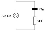
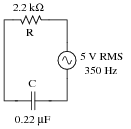
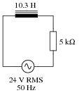
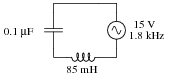
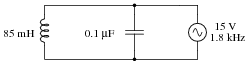
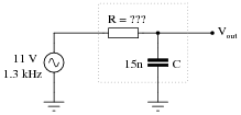
Which component, the resistor or the capacitor, will drop more voltage in this circuit?
|
|
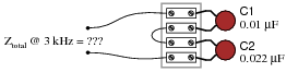
Also, calculate the total impedance (Ztotal) of this circuit, expressing it in both rectangular and polar forms.
Ztotal (rectangular form) = 5100 W - j4671 W
Ztotal (polar form) = 6916 W � -42.5o
Notes:
Ask your students how they were able to make the determination of greater voltage drop. Which method yields the fastest solution (i.e. requires the fewest steps)?
Question 3:
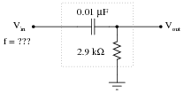
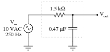
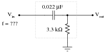
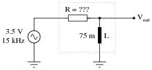
Determine the input frequency necessary to give the output voltage a phase shift of 40o:
|
|
Notes:
Phase-shifting circuits are very useful, and important to understand. They are particularly important in some types of oscillator circuits, which rely on RC networks such as this to provide certain phase shifts to sustain oscillation.
Question 4:
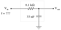
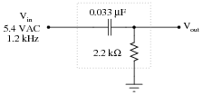
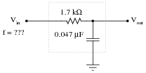
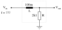
Determine the input frequency necessary to give the output voltage a phase shift of -38o:
|
|
Notes:
Phase-shifting circuits are very useful, and important to understand. They are particularly important in some types of oscillator circuits, which rely on RC networks such as this to provide certain phase shifts to sustain oscillation.
Question 5:
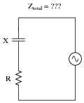
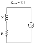
Write an equation that solves for the impedance of this series circuit. The equation need not solve for the phase angle between voltage and current, but merely provide a scalar figure for impedance (in ohms):
|
|
Notes:
Ask your students if this equation looks similar to any other mathematical equations they've seen before. If not, square both sides of the equation so it looks like Z2 = R2 + X2 and ask them again.
Question 6:
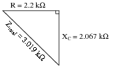
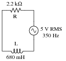
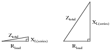
Draw a phasor diagram showing the trigonometric relationship between resistance, reactance, and impedance in this series circuit:
|
|
Show mathematically how the resistance and reactance combine in series to produce a total impedance (scalar quantities, all). Then, show how to analyze this same circuit using complex numbers: regarding each of the component as having its own impedance, demonstrating mathematically how these impedances add up to comprise the total impedance (in both polar and rectangular forms).
|
|
Scalar calculations
R = 2.2 kW XC = 2.067 kW
Zseries = �{R2 + XC2}
Zseries = �{22002 + 20672} = 3019 W
Complex number calculations
ZR = 2.2 kW � 0o ZC = 2.067 kW �-90o (Polar form)
ZR = 2.2 kW+ j0 W ZC = 0 W- j2.067 kW (Rectangular form)
Zseries = Z1 + Z2 + �Zn (General rule of series impedances)
Zseries = ZR + ZC (Specific application to this circuit)
Zseries = 2.2 kW � 0o + 2.067 kW �-90o = 3.019 kW �-43.2o
Zseries = (2.2 kW+ j0 W) + (0 W- j2.067 kW) = 2.2 kW- j2.067 kW
Notes:
I want students to see that there are two different ways of approaching a problem such as this: with scalar math and with complex number math. If students have access to calculators that can do complex-number arithmetic, the "complex" approach is actually simpler for series-parallel combination circuits, and it yields richer (more informative) results.
Ask your students to determine which of the approaches most resembles DC circuit calculations. Incidentally, this is why I tend to prefer complex-number AC circuit calculations over scalar calculations: because of the conceptual continuity between AC and DC. When you use complex numbers to represent AC voltages, currents, and impedances, almost all the rules of DC circuits still apply. The big exception, of course, is calculations involving power.
Question 7:
Solve for all voltages and currents in this series RC circuit, and also calculate the phase angle of the total impedance:
|
|
VR = 6.508 volts peak
I = 1.972 milliamps peak
QZ = -82.21o
Follow-up question: what would we have to do to get these answers in units RMS instead of units "peak"?
Notes:
Bring to your students' attention the fact that total voltage in this circuit is given in "peak" units rather than RMS, and what effect this has on our answers.
Students often have difficulty formulating a method of solution: determining what steps to take to get from the given conditions to a final answer. While it is helpful at first for you (the instructor) to show them, it is bad for you to show them too often, lest they stop thinking for themselves and merely follow your lead. A teaching technique I have found very helpful is to have students come up to the board (alone or in teams) in front of class to write their problem-solving strategies for all the others to see. They don't have to actually do the math, but rather outline the steps they would take, in the order they would take them. The following is a sample of a written problem-solving strategy for analyzing a series resistive-reactive AC circuit:
Step 1: Calculate all reactances (X).
Step 2: Draw an impedance triangle (Z ; R ; X), solving for Z
Step 3: Calculate circuit current using Ohm's Law: I = V/Z
Step 4: Calculate series voltage drops using Ohm's Law: V = I Z
Step 5: Check work by drawing a voltage triangle (Vtotal ; V1 ; V2), solving for Vtotal
By having students outline their problem-solving strategies, everyone gets an opportunity to see multiple methods of solution, and you (the instructor) get to see how (and if!) your students are thinking. An especially good point to emphasize in these öpen thinking" activities is how to check your work to see if any mistakes were made.
Question 8:
A student is asked to calculate the phase shift for the following circuit's output voltage, relative to the phase of the source voltage:
|
|
He recognizes this as a series circuit, and therefore realizes that a right triangle would be appropriate for representing component impedances and component voltage drops (because both impedance and voltage are quantities that add in series, and the triangle represents phasor addition):
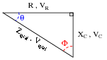
|
|
The problem now is, which angle does the student solve for in order to find the phase shift of Vout? The triangle contains two angles besides the 90o angle, Q and F. Which one represents the output phase shift, and more importantly, why?
Notes:
Too many students blindly use impedance and voltage triangles without really understand what they are and why they work. These same students will have no idea how to approach a problem like this. Work with them to help them understand!
Question 9:
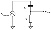
Calculate the output voltage of this phase-shifting circuit, expressing it in polar form (magnitude and phase angle relative to the source voltage):
|
|
Notes:
This is a very practical application of resistor-capacitor (RC) circuits: to introduce a phase shift to an AC signal. Examples of where a circuit such as this may be used include oscillators (to introduce phase shift into a feedback network for a total phase shift of 360o) and thyristor firing control circuits (phase-shifting the triggering voltage in relation to the source voltage).
Question 10:
Calculate the output voltage of this phase-shifting circuit, expressing it in polar form (magnitude and phase angle relative to the source voltage):
|
|
Notes:
This is a very practical application of resistor-capacitor (RC) circuits: to introduce a phase shift to an AC signal. Examples of where a circuit such as this may be used include oscillators (to introduce phase shift into a feedback network for a total phase shift of 360o) and thyristor firing control circuits (phase-shifting the triggering voltage in relation to the source voltage).
Question 11:
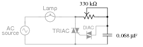
In this circuit, a series resistor-capacitor network creates a phase-shifted voltage for the "gate" terminal of a power-control device known as a TRIAC. All portions of the circuit except for the RC network are ßhaded" for de-emphasis:
|
|
Calculate how many degrees of phase shift the capacitor's voltage is, compared to the total voltage across the series RC network, assuming a frequency of 60 Hz, and a 50% potentiometer setting.
Challenge question: what effect will a change in potentiometer setting have on this phase angle? Specifically, will increasing the resistance make the phase shift approach -90o or approach 0o?
Notes:
In this question, I purposely omitted any reference to voltage levels, so the students would have to set up part of the problem themselves. The goal here is to build problem-solving skills.
Question 12:
Determine the input frequency necessary to give the output voltage a phase shift of 70o:
|
|
Notes:
Phase-shifting circuits are very useful, and important to understand. They are particularly important in some types of oscillator circuits, which rely on RC networks such as this to provide certain phase shifts to sustain oscillation.
Question 13:
Determine the input frequency necessary to give the output voltage a phase shift of -25o:
|
|
Notes:
Phase-shifting circuits are very useful, and important to understand. They are particularly important in some types of oscillator circuits, which rely on RC networks such as this to provide certain phase shifts to sustain oscillation.
Question 14:
Write an equation that solves for the impedance of this series circuit. The equation need not solve for the phase angle between voltage and current, but merely provide a scalar figure for impedance (in ohms):
|
|
Follow-up question: algebraically manipulate this equation to produce two more; one solving for R and the other solving for X.
Notes:
Ask your students if this equation looks similar to any other mathematical equations they've seen before. If not, square both sides of the equation so it looks like Z2 = R2 + X2 and ask them again.
Question 15:
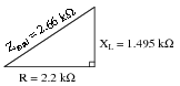
Draw a phasor diagram showing the trigonometric relationship between resistance, reactance, and impedance in this series circuit:
|
|
Show mathematically how the resistance and reactance combine in series to produce a total impedance (scalar quantities, all). Then, show how to analyze this same circuit using complex numbers: regarding component as having its own impedance, demonstrating mathematically how these impedances add up to comprise the total impedance (in both polar and rectangular forms).
|
|
Scalar calculations
R = 2.2 kW XL = 1.495 kW
Zseries = �{R2 + XL2}
Zseries = �{22002 + 14952} = 2660 W
Complex number calculations
ZR = 2.2 kW � 0o ZL = 1.495 kW � 90o (Polar form)
ZR = 2.2 kW+ j0 W ZL = 0 W+ j1.495 kW (Rectangular form)
Zseries = Z1 + Z2 + �Zn (General rule of series impedances)
Zseries = ZR + ZL (Specific application to this circuit)
Zseries = 2.2 kW � 0o + 1.495 kW � 90o = 2.66 kW � 34.2o
Zseries = (2.2 kW+ j0 W) + (0 W+ j1.495 kW) = 2.2 kW+ j1.495 kW
Notes:
I want students to see that there are two different ways of approaching a problem such as this: with scalar math and with complex number math. If students have access to calculators that can do complex-number arithmetic, the "complex" approach is actually simpler for series-parallel combination circuits, and it yields richer (more informative) results.
Ask your students to determine which of the approaches most resembles DC circuit calculations. Incidentally, this is why I tend to prefer complex-number AC circuit calculations over scalar calculations: because of the conceptual continuity between AC and DC. When you use complex numbers to represent AC voltages, currents, and impedances, almost all the rules of DC circuits still apply. The big exception, of course, is calculations involving power.
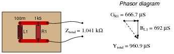
Question 16:
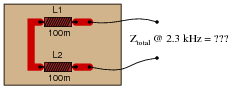
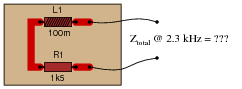
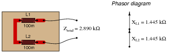
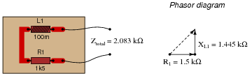
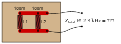
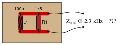
Calculate the total impedance for these two 100 mH inductors at 2.3 kHz, and draw a phasor diagram showing circuit impedances (Ztotal, R, and X):
|
|
Now, re-calculate impedance and re-draw the phasor impedance diagram supposing the second inductor is replaced by a 1.5 kW resistor:
|
|
|
|
|
|
Notes:
Phasor diagrams are powerful analytical tools, if one knows how to draw and interpret them. With hand calculators being so powerful and readily able to handle complex numbers in either polar or rectangular form, there is temptation to avoid phasor diagrams and let the calculator handle all the angle manipulation. However, students will have a much better understanding of phasors and complex numbers in AC circuits if you hold them accountable to representing quantities in that form.
Question 17:
Calculate the total impedance of this series LR circuit and then calculate the total circuit current:
|
|
Also, draw a phasor diagram showing how the individual component impedances relate to the total impedance.
I = 4.896 mA RMS
Notes:
This would be an excellent question to have students present methods of solution for. Sometimes I have students present nothing but their solution steps on the board in front of class (no arithmetic at all), in order to generate a discussion on problem-solving strategies. The important part of their education here is not to arrive at the correct answer or to memorize an algorithm for solving this type of problem, but rather how to think like a problem-solver, and how to methodically apply the math they know to the problem(s) at hand.
Question 18:
Calculate the magnitude and phase shift of the current through this inductor, taking into consideration its intrinsic winding resistance:
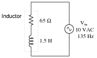
|
|
Notes:
Inductors are the least "pure" of any reactive component, due to significant quantities of resistance in the windings. Discuss this fact with your students, and what it means with reference to choosing inductors versus capacitors in circuit designs that could use either.
Question 19:
Solve for all voltages and currents in this series LR circuit:
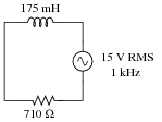
|
|
VR = 8.137 volts RMS
I = 11.46 milliamps RMS
Notes:
Nothing special here - just a straightforward exercise in series AC circuit calculations.
Students often have difficulty formulating a method of solution: determining what steps to take to get from the given conditions to a final answer. While it is helpful at first for you (the instructor) to show them, it is bad for you to show them too often, lest they stop thinking for themselves and merely follow your lead. A teaching technique I have found very helpful is to have students come up to the board (alone or in teams) in front of class to write their problem-solving strategies for all the others to see. They don't have to actually do the math, but rather outline the steps they would take, in the order they would take them. The following is a sample of a written problem-solving strategy for analyzing a series resistive-reactive AC circuit:
Step 1: Calculate all reactances (X).
Step 2: Draw an impedance triangle (Z ; R ; X), solving for Z
Step 3: Calculate circuit current using Ohm's Law: I = V/Z
Step 4: Calculate series voltage drops using Ohm's Law: V = I Z
Step 5: Check work by drawing a voltage triangle (Vtotal ; V1 ; V2), solving for Vtotal
By having students outline their problem-solving strategies, everyone gets an opportunity to see multiple methods of solution, and you (the instructor) get to see how (and if!) your students are thinking. An especially good point to emphasize in these öpen thinking" activities is how to check your work to see if any mistakes were made.
Question 20:
Solve for all voltages and currents in this series LR circuit, and also calculate the phase angle of the total impedance:
|
|
VR = 20.15 volts RMS
I = 4.030 milliamps RMS
QZ = 32.91o
Notes:
Nothing special here - just a straightforward exercise in series AC circuit calculations.
Students often have difficulty formulating a method of solution: determining what steps to take to get from the given conditions to a final answer. While it is helpful at first for you (the instructor) to show them, it is bad for you to show them too often, lest they stop thinking for themselves and merely follow your lead. A teaching technique I have found very helpful is to have students come up to the board (alone or in teams) in front of class to write their problem-solving strategies for all the others to see. They don't have to actually do the math, but rather outline the steps they would take, in the order they would take them. The following is a sample of a written problem-solving strategy for analyzing a series resistive-reactive AC circuit:
Step 1: Calculate all reactances (X).
Step 2: Draw an impedance triangle (Z ; R ; X), solving for Z
Step 3: Calculate circuit current using Ohm's Law: I = V/Z
Step 4: Calculate series voltage drops using Ohm's Law: V = I Z
Step 5: Check work by drawing a voltage triangle (Vtotal ; V1 ; V2), solving for Vtotal
By having students outline their problem-solving strategies, everyone gets an opportunity to see multiple methods of solution, and you (the instructor) get to see how (and if!) your students are thinking. An especially good point to emphasize in these öpen thinking" activities is how to check your work to see if any mistakes were made.
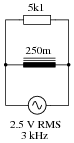
Question 21:
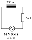
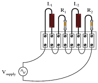
Determine the total current and all voltage drops in this circuit, stating your answers the way a multimeter would register them:
|
|
- �
- L1 = 250 mH
- �
- L2 = 60 mH
- �
- R1 = 6.8 kW
- �
- R2 = 1.2 kW
- �
- Vsupply = 13.4 V RMS
- �
- fsupply = 6.5 kHz
- �
- Itotal = 0.895 mA
- �
- VL1 = 9.14 V
- �
- VL2 = 2.19 V
- �
- VR1 = 6.08 V
- �
- VR2 = 1.07 V
- �
- Q = 57.71o
I suggest using a dual-trace oscilloscope to measure total voltage (across the supply terminals) and voltage drop across resistor R2. Theoretically, measuring the voltage dropped by either resistor would be fine, but R2 works better for practical reasons (oscilloscope input lead grounding). Phase shift then could be measured either in the time domain or by a Lissajous figure analysis.
Notes:
Some students many wonder what type of numerical result best corresponds to a multimeter's readings, if they do their calculations using complex numbers ("do I use polar or rectangular form, and if rectangular do I use the real or the imaginary part?"). The answers given for this question should clarify that point.
It is very important that students know how to apply this knowledge of AC circuit analysis to real-world situations. Asking students to determine how they would connect an oscilloscope to the circuit to measure Q is an exercise in developing their abstraction abilities between calculations and actual circuit scenarios.
Students often have difficulty formulating a method of solution: determining what steps to take to get from the given conditions to a final answer. While it is helpful at first for you (the instructor) to show them, it is bad for you to show them too often, lest they stop thinking for themselves and merely follow your lead. A teaching technique I have found very helpful is to have students come up to the board (alone or in teams) in front of class to write their problem-solving strategies for all the others to see. They don't have to actually do the math, but rather outline the steps they would take, in the order they would take them. The following is a sample of a written problem-solving strategy for analyzing a series resistive-reactive AC circuit:
Step 1: Calculate all reactances (X).
Step 2: Draw an impedance triangle (Z ; R ; X), solving for Z
Step 3: Calculate circuit current using Ohm's Law: I = V/Z
Step 4: Calculate series voltage drops using Ohm's Law: V = I Z
Step 5: Check work by drawing a voltage triangle (Vtotal ; V1 ; V2), solving for Vtotal
By having students outline their problem-solving strategies, everyone gets an opportunity to see multiple methods of solution, and you (the instructor) get to see how (and if!) your students are thinking. An especially good point to emphasize in these öpen thinking" activities is how to check your work to see if any mistakes were made.
Question 22:
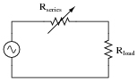
One way to vary the amount of power delivered to a resistive AC load is by varying another resistance connected in series:
|
|
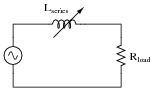
A problem with this power control strategy is that power is wasted in the series resistance (I2Rseries). A different strategy for controlling power is shown here, using a series inductance rather than resistance:
|
|
Explain why the latter circuit is more power-efficient than the former, and draw a phasor diagram showing how changes in Lseries affect Ztotal.
|
|
Follow-up question: the inductive circuit is not just more energy-efficient - it is safer as well. Identify a potential safety hazard that the resistive power-control circuit poses due to the energy dissipation of its variable resistor.
Notes:
If appropriate, you may want to mention devices called saturable reactors, which are used to control power in AC circuits by the exact same principle: varying a series inductance.
Question 23:
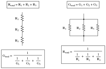
A quantity sometimes used in DC circuits is conductance, symbolized by the letter G. Conductance is the reciprocal of resistance (G = 1/R), and it is measured in the unit of siemens.
Expressing the values of resistors in terms of conductance instead of resistance has certain benefits in parallel circuits. Whereas resistances (R) add in series and "diminish" in parallel (with a somewhat complex equation), conductances (G) add in parallel and "diminish" in series. Thus, doing the math for series circuits is easier using resistance and doing math for parallel circuits is easier using conductance:

|
|
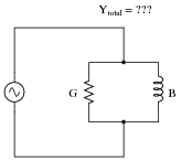
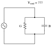
In AC circuits, we also have reciprocal quantities to reactance (X) and impedance (Z). The reciprocal of reactance is called susceptance (B = 1/X), and the reciprocal of impedance is called admittance (Y = 1/Z). Like conductance, both these reciprocal quantities are measured in units of siemens.
Write an equation that solves for the admittance (Y) of this parallel circuit. The equation need not solve for the phase angle between voltage and current, but merely provide a scalar figure for admittance (in siemens):
|
|
Follow-up question #1: draw a phasor diagram showing how Y, G, and B relate.
Follow-up question #2: re-write this equation using quantities of resistance (R), reactance (X), and impedance (Z), instead of conductance (G), susceptance (B), and admittance (Y).
Notes:
Ask your students if this equation looks familiar to them. It should!
The answer to the second follow-up question is a matter of algebraic substitution. Work through this process with your students, and then ask them to compare the resulting equation with other equations they've seen before. Does its form look familiar to them in any way?
Question 24:
Calculate the total impedance for these two 100 mH inductors at 2.3 kHz, and draw a phasor diagram showing circuit admittances (Ytotal, G, and B):
|
|
Now, re-calculate impedance and re-draw the phasor admittance diagram supposing the second inductor is replaced by a 1.5 kW resistor:
|
|

|
|
|
|
Challenge question: why are the susceptance vectors (BL1 and BL2) pointed down instead of up as impedance vectors for inductances typically are?
Notes:
Phasor diagrams are powerful analytical tools, if one knows how to draw and interpret them. With hand calculators being so powerful and readily able to handle complex numbers in either polar or rectangular form, there is temptation to avoid phasor diagrams and let the calculator handle all the angle manipulation. However, students will have a much better understanding of phasors and complex numbers in AC circuits if you hold them accountable to representing quantities in that form.
Question 25:
Calculate the individual currents through the inductor and through the resistor, the total current, and the total circuit impedance:
|
|
Also, draw a phasor diagram showing how the individual component currents relate to the total current.
IR = 490.2 mA RMS
Itotal = 722.3 mA RMS
Ztotal = 3.461 kW
Notes:
This would be an excellent question to have students present methods of solution for. Sometimes I have students present nothing but their solution steps on the board in front of class (no arithmetic at all), in order to generate a discussion on problem-solving strategies. The important part of their education here is not to arrive at the correct answer or to memorize an algorithm for solving this type of problem, but rather how to think like a problem-solver, and how to methodically apply the math they know to the problem(s) at hand.
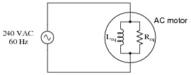
Question 26:
A large AC electric motor under load can be considered as a parallel combination of resistance and inductance:
|
|
Calculate the current necessary to power this motor if the equivalent resistance and inductance is 20 W and 238 mH, respectively.
Notes:
This is a practical example of a parallel LR circuit, as well as an example of how complex electrical devices may be "modeled" by collections of ideal components. To be honest, a loaded AC motor's characteristics are quite a bit more complex than what the parallel LR model would suggest, but at least it's a start!
Students often have difficulty formulating a method of solution: determining what steps to take to get from the given conditions to a final answer. While it is helpful at first for you (the instructor) to show them, it is bad for you to show them too often, lest they stop thinking for themselves and merely follow your lead. A teaching technique I have found very helpful is to have students come up to the board (alone or in teams) in front of class to write their problem-solving strategies for all the others to see. They don't have to actually do the math, but rather outline the steps they would take, in the order they would take them. The following is a sample of a written problem-solving strategy for analyzing a series resistive-reactive AC circuit:
Step 1: Calculate all reactances (X).
Step 2: Draw an impedance triangle (Z ; R ; X), solving for Z
Step 3: Calculate circuit current using Ohm's Law: I = V/Z
Step 4: Calculate series voltage drops using Ohm's Law: V = I Z
Step 5: Check work by drawing a voltage triangle (Vtotal ; V1 ; V2), solving for Vtotal
By having students outline their problem-solving strategies, everyone gets an opportunity to see multiple methods of solution, and you (the instructor) get to see how (and if!) your students are thinking. An especially good point to emphasize in these öpen thinking" activities is how to check your work to see if any mistakes were made.
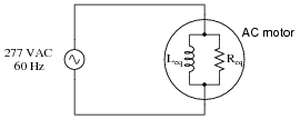
Question 27:
A large AC electric motor under load can be considered as a parallel combination of resistance and inductance:
|
|
Calculate the equivalent inductance (Leq) if the measured source current is 27.5 amps and the motor's equivalent resistance (Req) is 11.2 W.
Notes:
Here is a case where scalar calculations (R, G, X, B, Y) are much easier than complex number calculations (all Z) would be.
Students often have difficulty formulating a method of solution: determining what steps to take to get from the given conditions to a final answer. While it is helpful at first for you (the instructor) to show them, it is bad for you to show them too often, lest they stop thinking for themselves and merely follow your lead. A teaching technique I have found very helpful is to have students come up to the board (alone or in teams) in front of class to write their problem-solving strategies for all the others to see. They don't have to actually do the math, but rather outline the steps they would take, in the order they would take them. The following is a sample of a written problem-solving strategy for analyzing a series resistive-reactive AC circuit:
Step 1: Calculate all reactances (X).
Step 2: Draw an impedance triangle (Z ; R ; X), solving for Z
Step 3: Calculate circuit current using Ohm's Law: I = V/Z
Step 4: Calculate series voltage drops using Ohm's Law: V = I Z
Step 5: Check work by drawing a voltage triangle (Vtotal ; V1 ; V2), solving for Vtotal
By having students outline their problem-solving strategies, everyone gets an opportunity to see multiple methods of solution, and you (the instructor) get to see how (and if!) your students are thinking. An especially good point to emphasize in these öpen thinking" activities is how to check your work to see if any mistakes were made.
Question 28:
Determine the total current and all component currents in this circuit, stating your answers the way a multimeter would register them:

|
|
- �
- L1 = 1.2 H
- �
- L2 = 650 mH
- �
- R1 = 33 kW
- �
- R2 = 27 kW
- �
- Vsupply = 19.7 V RMS
- �
- fsupply = 4.5 kHz
- �
- Itotal = 2.12 mA
- �
- IL1 = 581 mA
- �
- IL2 = 1.07 mA
- �
- IR1 = 597 mA
- �
- IR2 = 730 mA
- �
- Q = 51.24o
Measuring Q with an oscilloscope requires the addition of a shunt resistor into this circuit, because oscilloscopes are (normally) only able to measure voltage, and there is no phase shift between any voltages in this circuit because all components are in parallel. I leave it to you to suggest where to insert the shunt resistor, what resistance value to select for the task, and how to connect the oscilloscope to the modified circuit.
Notes:
Some students many wonder what type of numerical result best corresponds to a multimeter's readings, if they do their calculations using complex numbers ("do I use polar or rectangular form, and if rectangular do I use the real or the imaginary part?"). The answers given for this question should clarify that point.
It is very important that students know how to apply this knowledge of AC circuit analysis to real-world situations. Asking students to determine how they would connect an oscilloscope to the circuit to measure Q is an exercise in developing their abstraction abilities between calculations and actual circuit scenarios.
Students often have difficulty formulating a method of solution: determining what steps to take to get from the given conditions to a final answer. While it is helpful at first for you (the instructor) to show them, it is bad for you to show them too often, lest they stop thinking for themselves and merely follow your lead. A teaching technique I have found very helpful is to have students come up to the board (alone or in teams) in front of class to write their problem-solving strategies for all the others to see. They don't have to actually do the math, but rather outline the steps they would take, in the order they would take them. The following is a sample of a written problem-solving strategy for analyzing a series resistive-reactive AC circuit:
Step 1: Calculate all reactances (X).
Step 2: Draw an impedance triangle (Z ; R ; X), solving for Z
Step 3: Calculate circuit current using Ohm's Law: I = V/Z
Step 4: Calculate series voltage drops using Ohm's Law: V = I Z
Step 5: Check work by drawing a voltage triangle (Vtotal ; V1 ; V2), solving for Vtotal
By having students outline their problem-solving strategies, everyone gets an opportunity to see multiple methods of solution, and you (the instructor) get to see how (and if!) your students are thinking. An especially good point to emphasize in these öpen thinking" activities is how to check your work to see if any mistakes were made.
Question 29:
Calculate the total impedances (complete with phase angles) for each of the following inductor-resistor circuits:
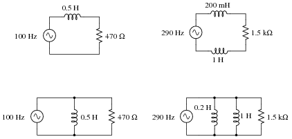
|
|
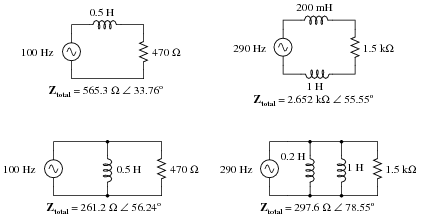
|
|
Notes:
Have your students explain how they solved for each impedance, step by step. You may find different approaches to solving the same problem(s), and your students will benefit from seeing the diversity of solution techniques.
Question 30:
A doorbell ringer has a solenoid with an inductance of 63 mH connected in parallel with a lamp (for visual indication) having a resistance of 150 ohms:
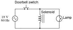
|
|
Calculate the phase shift of the total current (in units of degrees) in relation to the total supply voltage, when the doorbell switch is actuated.
Suppose the lamp turned on whenever the pushbutton switch was actuated, but the doorbell refused to ring. Identify what you think to be the most likely fault which could account for this problem.
Notes:
This would be an excellent question to have students present methods of solution for. Sometimes I have students present nothing but their solution steps on the board in front of class (no arithmetic at all), in order to generate a discussion on problem-solving strategies. The important part of their education here is not to arrive at the correct answer or to memorize an algorithm for solving this type of problem, but rather how to think like a problem-solver, and how to methodically apply the math they know to the problem(s) at hand.
Question 31:
An AC electric motor operating under loaded conditions draws a current of 11 amps (RMS) from the 120 volt (RMS) 60 Hz power lines. The measured phase shift between voltage and current for this motor is 34o, with voltage leading current.
Determine the equivalent parallel combination of resistance (R) and inductance (L) that is electrically equivalent to this operating motor.
Lparallel = 51.75 mH
Challenge question: in the parallel LR circuit, the resistor will dissipate a lot of energy in the form of heat. Does this mean that the electric motor, which is electrically equivalent to the LR network, will dissipate the same amount of heat? Explain why or why not.
Notes:
If students get stuck on the challenge question, remind them that an electric motor does mechanical work, which requires energy.
Question 32:
Doorbell circuits connect a small lamp in parallel with the doorbell pushbutton so that there is light at the button when it is not being pressed. The lamp's filament resistance is such that there is not enough current going through it to energize the solenoid coil when lit, which means the doorbell will ring only when the pushbutton switch shorts past the lamp:
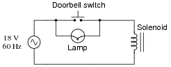
|
|
Suppose that such a doorbell circuit suddenly stops working one day, and the home owner assumes the power source has quit since the bell will not ring when the button is pressed and the lamp never lights. Although a dead power source is certainly possible, it is not the only possibility. Identify another possible failure in this circuit which would result in no doorbell action (no sound) and no light at the lamp.
- �
- Solenoid coil failed open
- �
- Wire broken anywhere in circuit
Notes:
After discussing alternative possibilities with your students, shift the discussion to one on how likely any of these failures are. For instance, how likely is it that the solenoid coil has developed an öpen" fault compared to the likelihood of a regular wire connection going bad in the circuit? How do either of these possibilities compare with the likelihood of the source failing as a result of a tripped circuit breaker or other power outage?
Question 33:
Calculate the total impedance offered by these two inductors to a sinusoidal signal with a frequency of 60 Hz:
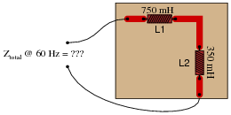
|
|
Show your work using two different problem-solving strategies:
- �
- Calculating total inductance (Ltotal) first, then total impedance (Ztotal).
- �
- Calculating individual impedances first (ZL1 and ZL2), then total impedance (Ztotal).
Do these two strategies yield the same total impedance value? Why or why not?
Ltotal = 1.1 H
Xtotal = 414.7 W
Ztotal = 414.7 W � 90o or Ztotal = 0 + j414.7 W
Second strategy:
XL1 = 282.7 W ZL1 = 282.7 W � 90o
XL2 = 131.9 W ZL2 = 131.9 W � 90o
Ztotal = 414.7 W � 90o or Ztotal = 0 + j414.7 W
Follow-up question: draw a phasor diagram showing how the two inductors' impedance phasors geometrically add to equal the total impedance.
Notes:
The purpose of this question is to get students to realize that any way they can calculate total impedance is correct, whether calculating total inductance and then calculating impedance from that, or by calculating the impedance of each inductor and then combining impedances to find a total impedance. This should be reassuring, because it means students have a way to check their work when analyzing circuits such as this!
Question 34:
Calculate the total impedance of this LR circuit, once using nothing but scalar numbers, and again using complex numbers:
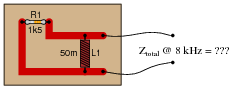
|
|
R1 = 1.5 kW GR1 = 666.7 mS
XL1 = 2.513 kW BL1 = 397.9 mS
Ytotal = �{G2 + B2} = 776.4 mS
Ztotal = [1/(Ytotal)] = 1.288 kW
Complex number calculations
R1 = 1.5 kW ZR1 = 1.5 kW � 0o
XL1 = 2.513 kW ZL1 = 2.513 kW � 90o
Ztotal = [ 1/([1/(ZR1)] + [1/(ZL1)])] = 1.288 kW � 30.83o
Notes:
Some electronics textbooks (and courses) tend to emphasize scalar impedance calculations, while others emphasize complex number calculations. While complex number calculations provide more informative results (a phase shift given in every variable!) and exhibit conceptual continuity with DC circuit analysis (same rules, similar formulae), the scalar approach lends itself better to conditions where students do not have access to calculators capable of performing complex number arithmetic. Yes, of course, you can do complex number arithmetic without a powerful calculator, but it's a lot more tedious and prone to errors than calculating with admittances, susceptances, and conductances (primarily because the phase shift angle is omitted for each of the variables).
Question 35:
Calculate the total impedance offered by these two inductors to a sinusoidal signal with a frequency of 120 Hz:
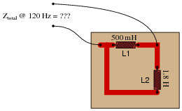
|
|
Show your work using three different problem-solving strategies:
- �
- Calculating total inductance (Ltotal) first, then total impedance (Ztotal).
- �
- Calculating individual admittances first (YL1 and YL2), then total admittance (Ytotal), then total impedance (Ztotal).
- �
- Using complex numbers: calculating individual impedances first (ZL1 and ZL2), then total impedance (Ztotal).
Do these two strategies yield the same total impedance value? Why or why not?
Ltotal = 391.3 mH
Xtotal = 295.0 W
Ztotal = 295.0 W � 90o or Ztotal = 0 + j295.0 W
Second strategy:
ZL1 = XL1 = 377.0 W
YL1 = [1/(ZL1)] = 2.653 mS
ZL1 = XL2 = 1.357 kW
YL2 = [1/(ZL2)] = 736.8 mS
Ytotal = 3.389 mS
Ztotal = [1/(Ytotal)] = 295 W
Third strategy: (using complex numbers)
XL1 = 377.0 W ZL1 = 377.0 W � 90o
XL2 = 1.357 kW ZL2 = 1.357 kW � 90o
Ztotal = 295.0 W � 90o or Ztotal = 0 + j295.0 W
Follow-up question: draw a phasor diagram showing how the two inductors' admittance phasors geometrically add to equal the total admittance.
Notes:
The purpose of this question is to get students to realize that any way they can calculate total impedance is correct, whether calculating total inductance and then calculating impedance from that, or by calculating the impedance of each inductor and then combining impedances to find a total impedance. This should be reassuring, because it means students have a way to check their work when analyzing circuits such as this!
Question 36:
Determine the input frequency necessary to give the output voltage a phase shift of 75o:
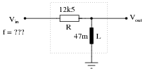
|
|
Also, write an equation that solves for frequency (f), given all the other variables (R, L, and phase angle q).
|
Notes:
Discuss with your students what a good procedure might be for calculating the unknown values in this problem, and also how they might check their work.
Students often have difficulty formulating a method of solution: determining what steps to take to get from the given conditions to a final answer. While it is helpful at first for you (the instructor) to show them, it is bad for you to show them too often, lest they stop thinking for themselves and merely follow your lead. A teaching technique I have found very helpful is to have students come up to the board (alone or in teams) in front of class to write their problem-solving strategies for all the others to see. They don't have to actually do the math, but rather outline the steps they would take, in the order they would take them.
By having students outline their problem-solving strategies, everyone gets an opportunity to see multiple methods of solution, and you (the instructor) get to see how (and if!) your students are thinking. An especially good point to emphasize in these öpen thinking" activities is how to check your work to see if any mistakes were made.
Question 37:
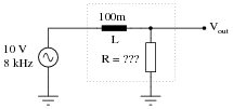
Determine the necessary resistor value to give the output voltage a phase shift of 44o:
|
|
Also, write an equation that solves for this resistance value (R), given all the other variables (f, L, and phase angle q).
|
Notes:
Discuss with your students what a good procedure might be for calculating the unknown values in this problem, and also how they might check their work.
Students often have difficulty formulating a method of solution: determining what steps to take to get from the given conditions to a final answer. While it is helpful at first for you (the instructor) to show them, it is bad for you to show them too often, lest they stop thinking for themselves and merely follow your lead. A teaching technique I have found very helpful is to have students come up to the board (alone or in teams) in front of class to write their problem-solving strategies for all the others to see. They don't have to actually do the math, but rather outline the steps they would take, in the order they would take them.
By having students outline their problem-solving strategies, everyone gets an opportunity to see multiple methods of solution, and you (the instructor) get to see how (and if!) your students are thinking. An especially good point to emphasize in these öpen thinking" activities is how to check your work to see if any mistakes were made.
Question 38:
Determine the input frequency necessary to give the output voltage a phase shift of -40o:
|
|
Also, write an equation that solves for frequency (f), given all the other variables (R, L, and phase angle q).
|
Notes:
Discuss with your students what a good procedure might be for calculating the unknown values in this problem, and also how they might check their work.
Students often have difficulty formulating a method of solution: determining what steps to take to get from the given conditions to a final answer. While it is helpful at first for you (the instructor) to show them, it is bad for you to show them too often, lest they stop thinking for themselves and merely follow your lead. A teaching technique I have found very helpful is to have students come up to the board (alone or in teams) in front of class to write their problem-solving strategies for all the others to see. They don't have to actually do the math, but rather outline the steps they would take, in the order they would take them.
By having students outline their problem-solving strategies, everyone gets an opportunity to see multiple methods of solution, and you (the instructor) get to see how (and if!) your students are thinking. An especially good point to emphasize in these öpen thinking" activities is how to check your work to see if any mistakes were made.
Question 39:
Determine the necessary resistor value to give the output voltage a phase shift of -60o:
|
|
Also, write an equation that solves for this resistance value (R), given all the other variables (f, L, and phase angle q).
|
Notes:
Discuss with your students what a good procedure might be for calculating the unknown values in this problem, and also how they might check their work.
Students often have difficulty formulating a method of solution: determining what steps to take to get from the given conditions to a final answer. While it is helpful at first for you (the instructor) to show them, it is bad for you to show them too often, lest they stop thinking for themselves and merely follow your lead. A teaching technique I have found very helpful is to have students come up to the board (alone or in teams) in front of class to write their problem-solving strategies for all the others to see. They don't have to actually do the math, but rather outline the steps they would take, in the order they would take them.
By having students outline their problem-solving strategies, everyone gets an opportunity to see multiple methods of solution, and you (the instructor) get to see how (and if!) your students are thinking. An especially good point to emphasize in these öpen thinking" activities is how to check your work to see if any mistakes were made.
Question 40:
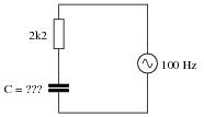
Calculate the necessary size of the capacitor to give this circuit a total impedance (Ztotal) of 4 kW, at a power supply frequency of 100 Hz:
|
|
Notes:
Nothing special to note here, just practice with the impedance triangle (and the capacitive reactance formula).
Question 41:
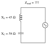
Capacitors and inductors are complementary components - both conceptually and mathematically, they seem to be almost exact opposites of each other. Calculate the total impedance of this series-connected inductor and capacitor network:
|
|
Follow-up question: does this circuit äppear" to be inductive or capacitive from the source's point of view?
Notes:
Here, the complementary nature of inductive and capacitive reactances is plain to see: they subtract in series. Challenge your students by asking them what the total impedance of this circuit would be if the two reactances were equal.
Question 42:
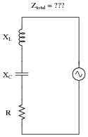
Write an equation that solves for the impedance of this series circuit. The equation need not solve for the phase angle between voltage and current, but merely provide a scalar figure for impedance (in ohms):
|
|
Notes:
Ask your students why one of the reactance terms under the radicand is positive and the other is negative. The way this equation is written, does it matter which term is negative? As your students if we would obtain the same answer if it were written as Ztotal = �{R2 + (XC - XL)2} instead. Challenge them to answer this question without using a calculator!
Question 43:
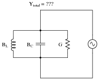
Write an equation that solves for the admittance of this parallel circuit. The equation need not solve for the phase angle between voltage and current, but merely provide a scalar figure for admittance (in siemens):
|
|
Notes:
Ask your students why one of the reactance terms under the radicand is positive and the other is negative. The way this equation is written, does it matter which term is negative? Ask your students if we would obtain the same answer if the equation were written as Ytotal = �{G2 + (BC - BL)2} instead. Challenge them to answer this question without using a calculator!
Question 44:
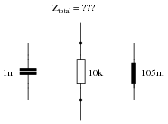
Calculate the total impedance of this parallel network, given a signal frequency of 12 kHz:
|
|
Notes:
Ask your students how they obtained the phase angle for this circuit. There is more than one way to calculate this!
Students often have difficulty formulating a method of solution: determining what steps to take to get from the given conditions to a final answer. While it is helpful at first for you (the instructor) to show them, it is bad for you to show them too often, lest they stop thinking for themselves and merely follow your lead. A teaching technique I have found very helpful is to have students come up to the board (alone or in teams) in front of class to write their problem-solving strategies for all the others to see. They don't have to actually do the math, but rather outline the steps they would take, in the order they would take them. The following is a sample of a written problem-solving strategy for analyzing a series resistive-reactive AC circuit:
Step 1: Calculate all reactances (X).
Step 2: Draw an impedance triangle (Z ; R ; X), solving for Z
Step 3: Calculate circuit current using Ohm's Law: I = V/Z
Step 4: Calculate series voltage drops using Ohm's Law: V = I Z
Step 5: Check work by drawing a voltage triangle (Vtotal ; V1 ; V2), solving for Vtotal
By having students outline their problem-solving strategies, everyone gets an opportunity to see multiple methods of solution, and you (the instructor) get to see how (and if!) your students are thinking. An especially good point to emphasize in these öpen thinking" activities is how to check your work to see if any mistakes were made.
Question 45:
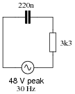
Is this circuit's overall behavior capacitive or inductive? In other words, from the perspective of the AC voltage source, does it äppear" as though a capacitor is being powered, or an inductor?
|
|
Now, suppose we take these same components and re-connect them in parallel rather than series. Does this change the circuit's overall äppearance" to the source? Does the source now ßee" an equivalent capacitor or an equivalent inductor? Explain your answer.
|
|
Follow-up question: which component "dominates" the behavior of a series LC circuit, the one with the least reactance or the one with the greatest reactance? Which component "dominates" the behavior of a parallel LC circuit, the one with the least reactance or the one with the greatest reactance?
Notes:
As usual, the real point of this question is to get students to think about the analytical procedure(s) they use, and to engage their minds in problem-solving behavior. Ask them why they think the circuits behave inductively or capacitively.
Students often have difficulty formulating a method of solution: determining what steps to take to get from the given conditions to a final answer. While it is helpful at first for you (the instructor) to show them, it is bad for you to show them too often, lest they stop thinking for themselves and merely follow your lead. A teaching technique I have found very helpful is to have students come up to the board (alone or in teams) in front of class to write their problem-solving strategies for all the others to see. They don't have to actually do the math, but rather outline the steps they would take, in the order they would take them. The following is a sample of a written problem-solving strategy for analyzing a series resistive-reactive AC circuit:
Step 1: Calculate all reactances (X).
Step 2: Draw an impedance triangle (Z ; R ; X), solving for Z
Step 3: Calculate circuit current using Ohm's Law: I = V/Z
Step 4: Calculate series voltage drops using Ohm's Law: V = I Z
Step 5: Check work by drawing a voltage triangle (Vtotal ; V1 ; V2), solving for Vtotal
By having students outline their problem-solving strategies, everyone gets an opportunity to see multiple methods of solution, and you (the instructor) get to see how (and if!) your students are thinking. An especially good point to emphasize in these öpen thinking" activities is how to check your work to see if any mistakes were made.
Question 46:
Suppose you are building a circuit and you need an impedance of 1500 W � -41o at a frequency of 600 Hz. What combination of components could you connect together in series to achieve this precise impedance?
Notes:
As usual, the most important part of your students' answers is not the figures themselves, but rather their methods of solution. Students should be very familiar with how to calculate the impedance of a series-connected group of components, but calculating component values from an impedance figure may be a challenge to some.
Question 47:
Calculate the impedance of a 145 mH inductor connected in series with 750 W resistor at a frequency of 1 kHz, then determine the necessary resistor and inductor values to create the exact same total impedance in a parallel configuration.
If connected in parallel: R = 1.857 kW ; L = 243.3 mH.
Hint: if you are having difficulty figuring out where to start in answering this question, consider the fact that these two circuits, if equivalent in total impedance, will draw the exact same amount of current from a common AC source at 1 kHz.
Notes:
This is an interesting question, requiring the student to think creatively about how to convert one configuration of circuit into another, while maintaining the same total effect. As usual, the real purpose of a question like this is to develop problem-solving strategies, rather than to simply obtain an answer.
Question 48:
Calculate the total impedance of these parallel-connected components, expressing it in polar form (magnitude and phase angle):
|
|
Also, draw an admittance triangle for this circuit.
|
|
Notes:
Some students may wonder why every side of the triangle is represented by a Y term, rather than Y for the hypotenuse, G for the adjacent, and B for the opposite. If students ask about this, remind them that conductance (G) and susceptance (B) are simple two different types of admittances (Y), just as resistance (R) and reactance (X) are simply two different types of impedances (Z).
Question 49:
Determine the necessary resistor value to give the output voltage a phase shift of -64o:
|
|
Also, write an equation that solves for this resistance value (R), given all the other variables (f, C, and phase angle q).
|
Notes:
Discuss with your students what a good procedure might be for calculating the unknown values in this problem, and also how they might check their work.
Students often have difficulty formulating a method of solution: determining what steps to take to get from the given conditions to a final answer. While it is helpful at first for you (the instructor) to show them, it is bad for you to show them too often, lest they stop thinking for themselves and merely follow your lead. A teaching technique I have found very helpful is to have students come up to the board (alone or in teams) in front of class to write their problem-solving strategies for all the others to see. They don't have to actually do the math, but rather outline the steps they would take, in the order they would take them.
By having students outline their problem-solving strategies, everyone gets an opportunity to see multiple methods of solution, and you (the instructor) get to see how (and if!) your students are thinking. An especially good point to emphasize in these öpen thinking" activities is how to check your work to see if any mistakes were made.
Question 50:
Calculate the total impedance offered by these two capacitors to a sinusoidal signal with a frequency of 3 kHz:
|
|
Show your work using two different problem-solving strategies:
- �
- Calculating total capacitance (Ctotal) first, then total impedance (Ztotal).
- �
- Calculating individual impedances first (ZC1 and ZC2), then total impedance (Ztotal).
Do these two strategies yield the same total impedance value? Why or why not?
Ctotal = 6.875 nF
Xtotal = 7.717 kW
Ztotal = 7.717 kW �-90o or Ztotal = 0 - j7.717 kW
Second strategy:
XC1 = 5.305 kW ZC1 = 5.305 kW �-90o
XC2 = 2.411 kW ZC1 = 2.411 kW �-90o
Ztotal = 7.717 kW �-90o or Ztotal = 0 - j7.717 kW
Notes:
A common misconception many students have about capacitive reactances and impedances is that they must interact öppositely" to how one would normally consider electrical opposition. That is, many students believe capacitive reactances and impedances should add in parallel and diminish in series, because that's what capacitance (in Farads) does! This is not true, however. Impedances always add in series and diminish in parallel, at least from the perspective of complex numbers. This is one of the reasons I favor AC circuit calculations using complex numbers: because then students may conceptually treat impedance just like they treat DC resistance.
The purpose of this question is to get students to realize that any way they can calculate total impedance is correct, whether calculating total capacitance and then calculating impedance from that, or by calculating the impedance of each capacitor and then combining impedances to find a total impedance. This should be reassuring, because it means students have a way to check their work when analyzing circuits such as this!
Question 51:
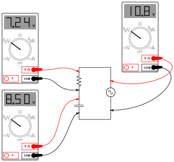
A student measures voltage drops in an AC circuit using three voltmeters and arrives at the following measurements:
|
|
Upon viewing these measurements, the student becomes very perplexed. Aren't voltage drops supposed to add in series, just as in DC circuits? Why, then, is the total voltage in this circuit only 10.8 volts and not 15.74 volts? How is it possible for the total voltage in an AC circuit to be substantially less than the simple sum of the components' voltage drops?
Another student, trying to be helpful, suggests that the answer to this question might have something to do with RMS versus peak measurements. A third student disagrees, proposing instead that at least one of the meters is badly out of calibration and thus not reading correctly.
When you are asked for your thoughts on this problem, you realize that neither of the answers proposed thus far are correct. Explain the real reason for the "discrepancy" in voltage measurements, and also explain how you could experimentally disprove the other answers (RMS vs. peak, and bad calibration).
I'll let you determine how to disprove the two incorrect explanations offered by the other students!
Challenge question: calculate a set of possible values for the capacitor and resistor that would generate these same voltage drops in a real circuit. Hint: you must also decide on a value of frequency for the power source.
Notes:
This question has two different layers: first, how to reconcile the ßtrange" voltage readings with Kirchhoff's Voltage Law; and second, how to experimentally validate the accuracy of the voltmeters and the fact that they are all registering the same type of voltage (RMS, peak, or otherwise, it doesn't matter). The first layer of this question regards the basic concepts of AC phase, while the second exercises troubleshooting and critical thinking skills. Be sure to discuss both of these topics in class with your students.
Question 52:
A quantity sometimes used in DC circuits is conductance, symbolized by the letter G. Conductance is the reciprocal of resistance (G = 1/R), and it is measured in the unit of siemens.
Expressing the values of resistors in terms of conductance instead of resistance has certain benefits in parallel circuits. Whereas resistances (R) add in series and "diminish" in parallel (with a somewhat complex equation), conductances (G) add in parallel and "diminish" in series. Thus, doing the math for series circuits is easier using resistance and doing math for parallel circuits is easier using conductance:
|
|
In AC circuits, we also have reciprocal quantities to reactance (X) and impedance (Z). The reciprocal of reactance is called susceptance (B = 1/X), and the reciprocal of impedance is called admittance (Y = 1/Z). Like conductance, both these reciprocal quantities are measured in units of siemens.
Write an equation that solves for the admittance (Y) of this parallel circuit. The equation need not solve for the phase angle between voltage and current, but merely provide a scalar figure for admittance (in siemens):
|
|
Follow-up question #1: draw a phasor diagram showing how Y, G, and B relate.
Follow-up question #2: re-write this equation using quantities of resistance (R), reactance (X), and impedance (Z), instead of conductance (G), susceptance (B), and admittance (Y).
Notes:
Ask your students if this equation looks familiar to them. It should!
The answer to the challenge question is a matter of algebraic substitution. Work through this process with your students, and then ask them to compare the resulting equation with other equations they've seen before. Does its form look familiar to them in any way?
Question 53:
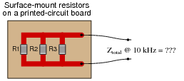
Calculate the total impedance offered by these three resistors to a sinusoidal signal with a frequency of 10 kHz:
- �
- R1 = 3.3 kW
- �
- R2 = 10 kW
- �
- R3 = 5 kW
|
|
State your answer in the form of a scalar number (not complex), but calculate it using two different strategies:
- �
- Calculate total resistance (Rtotal) first, then total impedance (Ztotal).
- �
- Calculate individual admittances first (YR1, YR2, and YR3), then total impedance (Ztotal).
Rtotal = 1.658 kW
Ztotal = 1.658 kW
Second strategy:
YR1 = 303 mS
YR2 = 100 mS
YR3 = 200 mS
Ytotal = 603 mS
Ztotal = 1.658 kW
Notes:
This question is set up to be more complex than it has to be. Its purpose is to get students thinking in terms of parallel admittances, in a manner similar to parallel conductances.
Question 54:
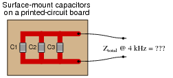
Calculate the total impedance offered by these three capacitors to a sinusoidal signal with a frequency of 4 kHz:
- �
- C1 = 0.1 mF
- �
- C2 = 0.047 mF
- �
- C3 = 0.033 mF
|
|
State your answer in the form of a scalar number (not complex), but calculate it using two different strategies:
- �
- Calculate total capacitance (Ctotal) first, then total impedance (Ztotal).
- �
- Calculate individual admittances first (YC1, YC2, and YC3), then total impedance (Ztotal).
Ctotal = 0.18 mF
Ztotal = 221 W
Second strategy:
YC1 = 2.51 mS
YC2 = 1.18 mS
YC3 = 829 mS
Ytotal = 4.52 mS
Ztotal = 221 W
Notes:
This question is another example of how multiple means of calculation will give you the same answer (if done correctly!). Make note to your students that this indicates an answer-checking strategy!
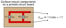
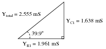
Question 55:
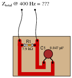
Calculate the total impedance of this RC circuit, once using nothing but scalar numbers, and again using complex numbers:
|
|
R1 = 7.9 kW GR1 = 126.6 mS
XC1 = 8.466 kW BC1 = 118.1 mS
Ytotal = �{G2 + B2} = 173.1 mS
Ztotal = [1/(Ytotal)] = 5.776 kW
Complex number calculations
R1 = 7.9 kW ZR1 = 7.9 kW � 0o
XC1 = 8.466 kW ZC1 = 8.466 kW �-90o
Ztotal = [ 1/([1/(ZR1)] + [1/(ZC1)])] = 5.776 kW �-43.02o
Notes:
Some electronics textbooks (and courses) tend to emphasize scalar impedance calculations, while others emphasize complex number calculations. While complex number calculations provide more informative results (a phase shift given in every variable!) and exhibit conceptual continuity with DC circuit analysis (same rules, similar formulae), the scalar approach lends itself better to conditions where students do not have access to calculators capable of performing complex number arithmetic. Yes, of course, you can do complex number arithmetic without a powerful calculator, but it's a lot more tedious and prone to errors than calculating with admittances, susceptances, and conductances (primarily because the phase shift angle is omitted for each of the variables).
Question 56:
Calculate the total impedance offered by these two capacitors to a sinusoidal signal with a frequency of 900 Hz:
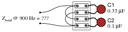
|
|
Show your work using three different problem-solving strategies:
- �
- Calculating total capacitance (Ctotal) first, then total impedance (Ztotal).
- �
- Calculating individual admittances first (YC1 and YC2), then total admittance (Ytotal), then total impedance (Ztotal).
- �
- Using complex numbers: calculating individual impedances first (ZC1 and ZC2), then total impedance (Ztotal).
Do these two strategies yield the same total impedance value? Why or why not?
Ctotal = 0.43 mF
Xtotal = 411.3 W
Ztotal = 411.3 W �-90o or Ztotal = 0 - j411.3 W
Second strategy:
ZC1 = XC1 = 535.9 W
YC1 = [1/(ZC1)] = 1.866 mS
ZC1 = XC2 = 1.768 kW
YC2 = [1/(ZC2)] = 565.5 mS
Ytotal = 2.432 mS
Ztotal = [1/(Ytotal)] = 411.3 W
Third strategy: (using complex numbers)
XC1 = 535.9 W ZC1 = 535.9 W �-90o
XC2 = 1.768 kW ZC1 = 1.768 kW �-90o
Ztotal = 411.3 W �-90o or Ztotal = 0 - j411.3 W
Notes:
A common misconception many students have about capacitive reactances and impedances is that they must interact öppositely" to how one would normally consider electrical opposition. That is, many students believe capacitive reactances and impedances should add in parallel and diminish in series, because that's what capacitance (in Farads) does! This is not true, however. Impedances always add in series and diminish in parallel, at least from the perspective of complex numbers. This is one of the reasons I favor AC circuit calculations using complex numbers: because then students may conceptually treat impedance just like they treat DC resistance.
The purpose of this question is to get students to realize that any way they can calculate total impedance is correct, whether calculating total capacitance and then calculating impedance from that, or by calculating the impedance of each capacitor and then combining impedances to find a total impedance. This should be reassuring, because it means students have a way to check their work when analyzing circuits such as this!
Question 57:
Due to the effects of a changing electric field on the dielectric of a capacitor, some energy is dissipated in capacitors subjected to AC. Generally, this is not very much, but it is there. This dissipative behavior is typically modeled as a series-connected resistance:
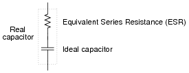
|
|
Calculate the magnitude and phase shift of the current through this capacitor, taking into consideration its equivalent series resistance (ESR):
|
|
Compare this against the magnitude and phase shift of the current for an ideal 0.22 mF capacitor.
I = 3.732212 mA � 90.00o for the ideal capacitor.
Follow-up question #1: can this ESR be detected by a DC meter check of the capacitor? Why or why not?
Follow-up question #2: explain how the ESR of a capacitor can lead to physical heating of the component, especially under high-voltage, high-frequency conditions. What safety concerns might arise as a result of this?
Notes:
Although capacitors do contain their own parasitic effects, ESR being one of them, they still tend to be much "purer" components than inductors for general use. This is another reason why capacitors are generally favored over inductors in applications where either will suffice.
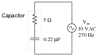
Question 58:
Solve for all voltages and currents in this series RC circuit:
|
|
VR = 4.248 volts RMS
I = 903.9 mA RMS
Follow-up question: identify the consequences of a shorted capacitor in this circuit, with regard to circuit current and component voltage drops.
Notes:
Nothing special here - just a straightforward exercise in series AC circuit calculations.
Students often have difficulty formulating a method of solution: determining what steps to take to get from the given conditions to a final answer. While it is helpful at first for you (the instructor) to show them, it is bad for you to show them too often, lest they stop thinking for themselves and merely follow your lead. A teaching technique I have found very helpful is to have students come up to the board (alone or in teams) in front of class to write their problem-solving strategies for all the others to see. They don't have to actually do the math, but rather outline the steps they would take, in the order they would take them. The following is a sample of a written problem-solving strategy for analyzing a series resistive-reactive AC circuit:
Step 1: Calculate all reactances (X).
Step 2: Draw an impedance triangle (Z ; R ; X), solving for Z
Step 3: Calculate circuit current using Ohm's Law: I = V/Z
Step 4: Calculate series voltage drops using Ohm's Law: V = I Z
Step 5: Check work by drawing a voltage triangle (Vtotal ; V1 ; V2), solving for Vtotal
By having students outline their problem-solving strategies, everyone gets an opportunity to see multiple methods of solution, and you (the instructor) get to see how (and if!) your students are thinking. An especially good point to emphasize in these öpen thinking" activities is how to check your work to see if any mistakes were made.
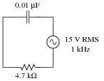
Question 59:
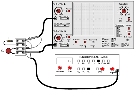
A technician needs to know the value of a capacitor, but does not have a capacitance meter nearby. In lieu of this, the technician sets up the following circuit to measure capacitance:
|
|
You happen to walk by this technician's workbench and ask, "How does this measurement setup work?" The technician responds, "You connect a resistor of known value (R) in series with the capacitor of unknown value (Cx), then adjust the generator frequency until the oscilloscope shows the two voltage drops to be equal, and then you calculate Cx."
Explain how this system works, in your own words. Also, write the formula you would use to calculate the value of Cx given f and R.
|
Follow-up question: could you use a similar setup to measure the inductance of an unknown inductor Lx? Why or why not?
Challenge question: astute observers will note that this setup might not work in real life because the ground connection of the oscilloscope is not common with one of the function generator's leads. Explain why this might be a problem, and suggest a practical solution for it.
Notes:
This method of measuring capacitance (or inductance for that matter) is fairly old, and works well if the unknown component has a high Q value.
Question 60:
If the dielectric substance between a capacitor's plates is not a perfect insulator, there will be a path for direct current (DC) from one plate to the other. This is typically called leakage resistance, and it is modeled as a shunt resistance to an ideal capacitance:
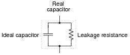
|
|
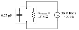
Calculate the magnitude and phase shift of the current drawn by this real capacitor, if powered by a sinusoidal voltage source of 30 volts RMS at 400 Hz:
|
|
Compare this against the magnitude and phase shift of the current for an ideal capacitor (no leakage).
I = 56.548668 mA � 90.00o for the ideal capacitor.
Notes:
Discuss with your students the fact that electrolytic capacitors typically have more leakage (less Rleakage) than most other capacitor types, due to the thinness of the dielectric oxide layer.
Students often have difficulty formulating a method of solution: determining what steps to take to get from the given conditions to a final answer. While it is helpful at first for you (the instructor) to show them, it is bad for you to show them too often, lest they stop thinking for themselves and merely follow your lead. A teaching technique I have found very helpful is to have students come up to the board (alone or in teams) in front of class to write their problem-solving strategies for all the others to see. They don't have to actually do the math, but rather outline the steps they would take, in the order they would take them. The following is a sample of a written problem-solving strategy for analyzing a series resistive-reactive AC circuit:
Step 1: Calculate all reactances (X).
Step 2: Draw an impedance triangle (Z ; R ; X), solving for Z
Step 3: Calculate circuit current using Ohm's Law: I = V/Z
Step 4: Calculate series voltage drops using Ohm's Law: V = I Z
Step 5: Check work by drawing a voltage triangle (Vtotal ; V1 ; V2), solving for Vtotal
By having students outline their problem-solving strategies, everyone gets an opportunity to see multiple methods of solution, and you (the instructor) get to see how (and if!) your students are thinking. An especially good point to emphasize in these öpen thinking" activities is how to check your work to see if any mistakes were made.
Question 61:
Voltage divider circuits may be constructed from reactive components just as easily as they may be constructed from resistors. Take this capacitive voltage divider, for instance:
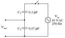
|
|
Calculate the magnitude and phase shift of Vout. Also, describe what advantages a capacitive voltage divider might have over a resistive voltage divider.
Follow-up question #1: explain why the division ratio of a capacitive voltage divider remains constant with changes in signal frequency, even though we know that the reactance of the capacitors (XC1 and XC2) will change.
Follow-up question #2: one interesting feature of capacitive voltage dividers is that they harbor the possibility of electric shock after being disconnected from the voltage source, if the source voltage is high enough and if the disconnection happens at just the right time. Explain why a capacitive voltage divider poses this threat whereas a resistive voltage divider does not. Also, identify what the time of disconnection from the AC voltage source has to do with shock hazard.
Notes:
Capacitive voltage dividers find use in high-voltage AC instrumentation, due to some of the advantages they exhibit over resistive voltage dividers. Your students should take special note of the phase angle for the capacitor's voltage drop. Why it is 0 degrees, and not some other angle?
Question 62:
Determine the input frequency necessary to give the output voltage a phase shift of 25o:
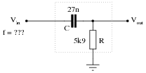
|
|
Also, write an equation that solves for frequency (f), given all the other variables (R, C, and phase angle q).
|
Notes:
Discuss with your students what a good procedure might be for calculating the unknown values in this problem, and also how they might check their work.
Students often have difficulty formulating a method of solution: determining what steps to take to get from the given conditions to a final answer. While it is helpful at first for you (the instructor) to show them, it is bad for you to show them too often, lest they stop thinking for themselves and merely follow your lead. A teaching technique I have found very helpful is to have students come up to the board (alone or in teams) in front of class to write their problem-solving strategies for all the others to see. They don't have to actually do the math, but rather outline the steps they would take, in the order they would take them.
By having students outline their problem-solving strategies, everyone gets an opportunity to see multiple methods of solution, and you (the instructor) get to see how (and if!) your students are thinking. An especially good point to emphasize in these öpen thinking" activities is how to check your work to see if any mistakes were made.
Question 63:
Determine the necessary resistor value to give the output voltage a phase shift of 58o:
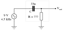
|
|
Also, write an equation that solves for this resistance value (R), given all the other variables (f, C, and phase angle q).
|
Notes:
Discuss with your students what a good procedure might be for calculating the unknown values in this problem, and also how they might check their work.
Students often have difficulty formulating a method of solution: determining what steps to take to get from the given conditions to a final answer. While it is helpful at first for you (the instructor) to show them, it is bad for you to show them too often, lest they stop thinking for themselves and merely follow your lead. A teaching technique I have found very helpful is to have students come up to the board (alone or in teams) in front of class to write their problem-solving strategies for all the others to see. They don't have to actually do the math, but rather outline the steps they would take, in the order they would take them.
By having students outline their problem-solving strategies, everyone gets an opportunity to see multiple methods of solution, and you (the instructor) get to see how (and if!) your students are thinking. An especially good point to emphasize in these öpen thinking" activities is how to check your work to see if any mistakes were made.
Question 64:
Use algebraic substitution to generate an equation expressing the output voltage of the following circuit given the input voltage, the input frequency, the capacitor value, and the resistor value:
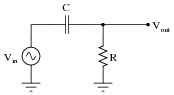
|
|
Vout =
|
Notes:
Discuss with your students what a good procedure might be for calculating the unknown values in this problem, and also how they might check their work.
Students often have difficulty formulating a method of solution: determining what steps to take to get from the given conditions to a final answer. While it is helpful at first for you (the instructor) to show them, it is bad for you to show them too often, lest they stop thinking for themselves and merely follow your lead. A teaching technique I have found very helpful is to have students come up to the board (alone or in teams) in front of class to write their problem-solving strategies for all the others to see. They don't have to actually do the math, but rather outline the steps they would take, in the order they would take them.
By having students outline their problem-solving strategies, everyone gets an opportunity to see multiple methods of solution, and you (the instructor) get to see how (and if!) your students are thinking. An especially good point to emphasize in these öpen thinking" activities is how to check your work to see if any mistakes were made.
Question 65:
Use algebraic substitution to generate an equation expressing the output voltage of the following circuit given the input voltage, the input frequency, the capacitor value, and the resistor value:
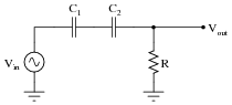
|
|
Vout =
|
Notes:
Discuss with your students what a good procedure might be for calculating the unknown values in this problem, and also how they might check their work.
Students often have difficulty formulating a method of solution: determining what steps to take to get from the given conditions to a final answer. While it is helpful at first for you (the instructor) to show them, it is bad for you to show them too often, lest they stop thinking for themselves and merely follow your lead. A teaching technique I have found very helpful is to have students come up to the board (alone or in teams) in front of class to write their problem-solving strategies for all the others to see. They don't have to actually do the math, but rather outline the steps they would take, in the order they would take them.
By having students outline their problem-solving strategies, everyone gets an opportunity to see multiple methods of solution, and you (the instructor) get to see how (and if!) your students are thinking. An especially good point to emphasize in these öpen thinking" activities is how to check your work to see if any mistakes were made.
Question 66:
Determine the total current and all voltage drops in this circuit, stating your answers the way a multimeter would register them:
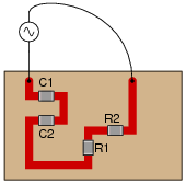
|
|
- �
- C1 = 125 pF
- �
- C2 = 71 pF
- �
- R1 = 6.8 kW
- �
- R2 = 1.2 kW
- �
- Vsupply = 20 V RMS
- �
- fsupply = 950 kHz
- �
- Itotal = 2.269 mA
- �
- VC1 = 3.041 V
- �
- VC2 = 5.354 V
- �
- VR1 = 15.43 V
- �
- VR2 = 2.723 V
- �
- Q = -24.82o (voltage lagging current)
I suggest using a dual-trace oscilloscope to measure total voltage (across the supply terminals) and voltage drop across resistor R2. Theoretically, measuring the voltage dropped by either resistor would be fine, but R2 works better for practical reasons (oscilloscope input lead grounding). Phase shift then could be measured either in the time domain or by a Lissajous figure analysis.
Notes:
Some students many wonder what type of numerical result best corresponds to a multimeter's readings, if they do their calculations using complex numbers ("do I use polar or rectangular form, and if rectangular do I use the real or the imaginary part?"). The answers given for this question should clarify that point.
It is very important that students know how to apply this knowledge of AC circuit analysis to real-world situations. Asking students to determine how they would connect an oscilloscope to the circuit to measure Q is an exercise in developing their abstraction abilities between calculations and actual circuit scenarios.
It is noteworthy that the low capacitances shown here approach parasitic capacitances between circuit board traces. In other words, whoever designs a circuit to operate at 950 kHz cannot simply place components at will on the board, but must consider the traces themselves to be circuit elements (both capacitive and inductive in nature!). The calculations used to obtain the given answers, of course, assume ideal conditions where the PC board is not considered to possess capacitance or inductance.
Students often have difficulty formulating a method of solution: determining what steps to take to get from the given conditions to a final answer. While it is helpful at first for you (the instructor) to show them, it is bad for you to show them too often, lest they stop thinking for themselves and merely follow your lead. A teaching technique I have found very helpful is to have students come up to the board (alone or in teams) in front of class to write their problem-solving strategies for all the others to see. They don't have to actually do the math, but rather outline the steps they would take, in the order they would take them. The following is a sample of a written problem-solving strategy for analyzing a series resistive-reactive AC circuit:
Step 1: Calculate all reactances (X).
Step 2: Draw an impedance triangle (Z ; R ; X), solving for Z
Step 3: Calculate circuit current using Ohm's Law: I = V/Z
Step 4: Calculate series voltage drops using Ohm's Law: V = I Z
Step 5: Check work by drawing a voltage triangle (Vtotal ; V1 ; V2), solving for Vtotal
By having students outline their problem-solving strategies, everyone gets an opportunity to see multiple methods of solution, and you (the instructor) get to see how (and if!) your students are thinking. An especially good point to emphasize in these öpen thinking" activities is how to check your work to see if any mistakes were made.
Question 67:
Calculate the voltage drops across all components in this circuit, expressing them in complex (polar) form with magnitudes and phase angles each:
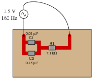
|
|
VC2 = 0.921 V �-52.11o
VR1 = 1.184 V � 37.90o
Follow-up question: how much phase shift is there between the capacitors' voltage drop and the resistor's voltage drop? Explain why this value is what it is.
Notes:
The first challenge of this question is for students to figure out how to reduce this series-parallel combination to something simpler. Fortunately, this is very easy to do if one remembers the properties of parallel capacitances.
Students may be surprised to discover the phase shift between VC and VR is the value it is. However, this should not remain a mystery. Discuss this with your class, taking time for all of them to understand why the voltage phasors of a resistor and a capacitor in a simple series circuit will always be orthogonal.
Students often have difficulty formulating a method of solution: determining what steps to take to get from the given conditions to a final answer. While it is helpful at first for you (the instructor) to show them, it is bad for you to show them too often, lest they stop thinking for themselves and merely follow your lead. A teaching technique I have found very helpful is to have students come up to the board (alone or in teams) in front of class to write their problem-solving strategies for all the others to see. They don't have to actually do the math, but rather outline the steps they would take, in the order they would take them. The following is a sample of a written problem-solving strategy for analyzing a series resistive-reactive AC circuit:
Step 1: Calculate all reactances (X).
Step 2: Draw an impedance triangle (Z ; R ; X), solving for Z
Step 3: Calculate circuit current using Ohm's Law: I = V/Z
Step 4: Calculate series voltage drops using Ohm's Law: V = I Z
Step 5: Check work by drawing a voltage triangle (Vtotal ; V1 ; V2), solving for Vtotal
By having students outline their problem-solving strategies, everyone gets an opportunity to see multiple methods of solution, and you (the instructor) get to see how (and if!) your students are thinking. An especially good point to emphasize in these öpen thinking" activities is how to check your work to see if any mistakes were made.
Question 68:
Determine the phase angle (Q) of the current in this circuit, with respect to the supply voltage:
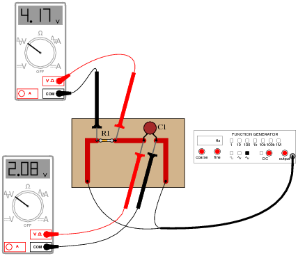
|
|
Challenge question: explain how the following phasor diagram was determined for this problem:
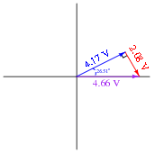
|
|
Notes:
This is an interesting question for a couple of reasons. First, students must determine how they will measure phase shift with just the two voltage indications shown by the meters. This may present a significant challenge for some. Discuss problem-solving strategies in class so that students understand how and why it is possible to determine Q.
Secondly, this is an interesting question because it shows how something as abstract as phase angle can be measured with just a voltmeter - no oscilloscope required! Not only that, but we don't even have to know the component values either! Note that this technique works only for simple circuits.
A practical point to mention here is that multimeters have frequency limits which must be considered when taking measurements on electronic circuits. Some high-quality handheld digital meters have frequency limits of hundred of kilohertz, while others fail to register accurately at only a few thousand hertz. Unless we knew these two digital voltmeters were sufficient for measuring at the signal frequency, their indications would be useless to us.
Question 69:
Calculate the total (source) current in this parallel RC circuit, based on the readings taken by the dual-trace oscilloscope (both of the inductive current probes show branch currents in units of 1 amp per division):
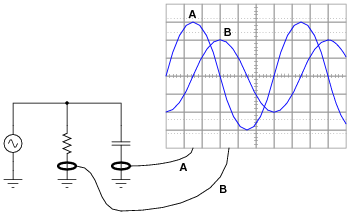
|
|
Itotal =
Notes:
This is a really simple trigonometry problem, disguised by the necessity of having to interpret the oscilloscope display.
Question 70:
Calculate the total impedances (complete with phase angles) for each of the following capacitor-resistor circuits:
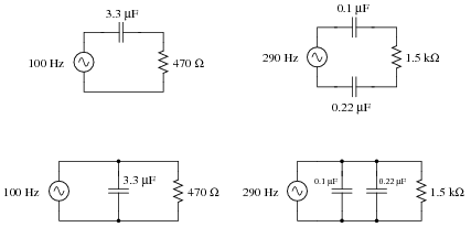
|
|
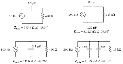
|
|
Notes:
Have your students explain how they solved for each impedance, step by step. You may find different approaches to solving the same problem(s), and your students will benefit from seeing the diversity of solution techniques.
Question 71:
Complete the table of values for this circuit, representing all quantities in complex-number form (either polar or rectangular, your choice):
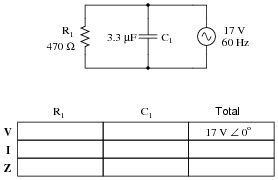
|
|
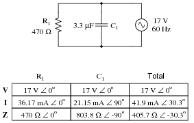
|
|
Notes:
Ask your students to share their problem-solving techniques for this question: how they solved for each parameter and in what order they performed the calculations.
Question 72:
Determine the size of capacitor (in Farads) necessary to create a total current of 11.3 mA in this parallel RC circuit:
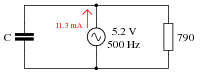
|
|
Notes:
Have your students explain how they solved for each impedance, step by step. You may find different approaches to solving the same problem(s), and your students will benefit from seeing the diversity of solution techniques.
Question 73:
The input impedance of an electrical test instrument is a very important parameter in some applications, because of how the instrument may load the circuit being tested. Oscilloscopes are no different from voltmeters in this regard:
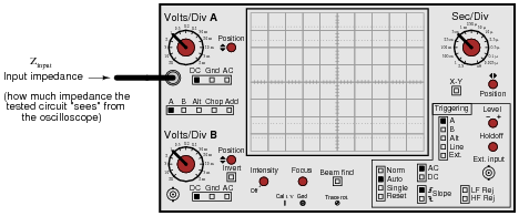
|
|
Typical input impedance for an oscilloscope is 1 MW of resistance, in parallel with a small amount of capacitance. At low frequencies, the reactance of this capacitance is so high that it may be safely ignored. At high frequencies, though, it may become a substantial load to the circuit under test:
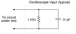
|
|
Calculate how many ohms of impedance this oscilloscope input (equivalent circuit shown in the above schematic) will impose on a circuit with a signal frequency of 150 kHz.
Follow-up question: what are the respective input impedances for ideal voltmeters and ideal ammeters? Explain why each ideal instrument needs to exhibit these impedances in order to accurately measure voltage and current (respectively) with the least ïmpact" to the circuit under test.
Notes:
Mention to your students that this capacitive loading effect only gets worse when a cable is attached to the oscilloscope input. The calculation performed for this question is only for the input of the oscilloscope itself, not including whatever capacitance may be included in the test probe cable!
This is one of the reasons why ×10 probes are used with oscilloscopes: to minimize the loading effect on the tested circuit.
Question 74:
If the source voltage in this circuit is assumed to be the phase reference (that is, the voltage is defined to be at an angle of 0 degrees), determine the relative phase angles of each current in this parallel circuit:
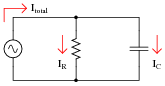
|
|
- �
- QI(R) =
- �
- QI(C) =
- �
- QI(total) =
- �
- QI(R) = 0o
- �
- QI(C) = 90o
- �
- QI(total) = some positive angle between 0o and 90o, exclusive
Notes:
Some students will be confused about the positive phase angles, since this is a capacitive circuit and they have learned to associate negative angles with capacitors. It is important for these students to realize, though, that the negative angles they immediately associate with capacitors are in reference to impedance and not necessarily to other variables in the circuit!
Question 75:
Calculate the voltage dropped across the inductor, the capacitor, and the 8-ohm speaker in this sound system at the following frequencies, given a constant source voltage of 15 volts:
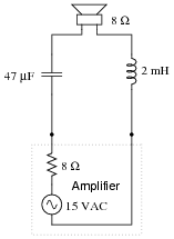
|
|
- �
- f = 200 Hz
- �
- f = 550 Hz
- �
- f = 900 Hz
Regard the speaker as nothing more than an 8-ohm resistor.
- �
- f = 200 Hz ; VL = 1.750 V ; VC = 11.79 V ; Vspeaker = 5.572 V
- �
- f = 550 Hz ; VL = 6.472 V ; VC = 5.766 V ; Vspeaker = 7.492 V
- �
- f = 900 Hz ; VL = 9.590 V ; VC = 3.763 V ; Vspeaker = 6.783 V
This circuit is known as a midrange crossover in stereo system design.
Notes:
This is an interesting circuit to analyze. Note how, out of the three frequency points we performed calculations at, the speaker's voltage is greatest at the middle frequency. Note also how the inductor and capacitor drop very disparate amounts of voltage at the high and low frequencies. Discuss this circuit's behavior with your students, and ask them what practical function this circuit performs.
Students often have difficulty formulating a method of solution: determining what steps to take to get from the given conditions to a final answer. While it is helpful at first for you (the instructor) to show them, it is bad for you to show them too often, lest they stop thinking for themselves and merely follow your lead. A teaching technique I have found very helpful is to have students come up to the board (alone or in teams) in front of class to write their problem-solving strategies for all the others to see. They don't have to actually do the math, but rather outline the steps they would take, in the order they would take them. The following is a sample of a written problem-solving strategy for analyzing a series resistive-reactive AC circuit:
Step 1: Calculate all reactances (X).
Step 2: Draw an impedance triangle (Z ; R ; X), solving for Z
Step 3: Calculate circuit current using Ohm's Law: I = V/Z
Step 4: Calculate series voltage drops using Ohm's Law: V = I Z
Step 5: Check work by drawing a voltage triangle (Vtotal ; V1 ; V2), solving for Vtotal
By having students outline their problem-solving strategies, everyone gets an opportunity to see multiple methods of solution, and you (the instructor) get to see how (and if!) your students are thinking. An especially good point to emphasize in these öpen thinking" activities is how to check your work to see if any mistakes were made.