Series-parallel combination AC circuits
Question 1:
| Don't just sit there! Build something!! |
Learning to mathematically analyze circuits requires much study and practice. Typically, students practice by working through lots of sample problems and checking their answers against those provided by the textbook or the instructor. While this is good, there is a much better way.
You will learn much more by actually building and analyzing real circuits, letting your test equipment provide the änswers" instead of a book or another person. For successful circuit-building exercises, follow these steps:
- 1.
- Carefully measure and record all component values prior to circuit construction.
- 2.
- Draw the schematic diagram for the circuit to be analyzed.
- 3.
- Carefully build this circuit on a breadboard or other convenient medium.
- 4.
- Check the accuracy of the circuit's construction, following each wire to each connection point, and verifying these elements one-by-one on the diagram.
- 5.
- Mathematically analyze the circuit, solving for all voltage and current values.
- 6.
- Carefully measure all voltages and currents, to verify the accuracy of your analysis.
- 7.
- If there are any substantial errors (greater than a few percent), carefully check your circuit's construction against the diagram, then carefully re-calculate the values and re-measure.
For AC circuits where inductive and capacitive reactances (impedances) are a significant element in the calculations, I recommend high quality (high-Q) inductors and capacitors, and powering your circuit with low frequency voltage (power-line frequency works well) to minimize parasitic effects. If you are on a restricted budget, I have found that inexpensive electronic musical keyboards serve well as "function generators" for producing a wide range of audio-frequency AC signals. Be sure to choose a keyboard "voice" that closely mimics a sine wave (the "panflute" voice is typically good), if sinusoidal waveforms are an important assumption in your calculations.
As usual, avoid very high and very low resistor values, to avoid measurement errors caused by meter "loading". I recommend resistor values between 1 kW and 100 kW.
One way you can save time and reduce the possibility of error is to begin with a very simple circuit and incrementally add components to increase its complexity after each analysis, rather than building a whole new circuit for each practice problem. Another time-saving technique is to re-use the same components in a variety of different circuit configurations. This way, you won't have to measure any component's value more than once.
Notes:
It has been my experience that students require much practice with circuit analysis to become proficient. To this end, instructors usually provide their students with lots of practice problems to work through, and provide answers for students to check their work against. While this approach makes students proficient in circuit theory, it fails to fully educate them.
Students don't just need mathematical practice. They also need real, hands-on practice building circuits and using test equipment. So, I suggest the following alternative approach: students should build their own "practice problems" with real components, and try to mathematically predict the various voltage and current values. This way, the mathematical theory "comes alive," and students gain practical proficiency they wouldn't gain merely by solving equations.
Another reason for following this method of practice is to teach students scientific method: the process of testing a hypothesis (in this case, mathematical predictions) by performing a real experiment. Students will also develop real troubleshooting skills as they occasionally make circuit construction errors.
Spend a few moments of time with your class to review some of the "rules" for building circuits before they begin. Discuss these issues with your students in the same Socratic manner you would normally discuss the worksheet questions, rather than simply telling them what they should and should not do. I never cease to be amazed at how poorly students grasp instructions when presented in a typical lecture (instructor monologue) format!
An excellent way to introduce students to the mathematical analysis of real circuits is to have them first determine component values (L and C) from measurements of AC voltage and current. The simplest circuit, of course, is a single component connected to a power source! Not only will this teach students how to set up AC circuits properly and safely, but it will also teach them how to measure capacitance and inductance without specialized test equipment.
A note on reactive components: use high-quality capacitors and inductors, and try to use low frequencies for the power supply. Small step-down power transformers work well for inductors (at least two inductors in one package!), so long as the voltage applied to any transformer winding is less than that transformer's rated voltage for that winding (in order to avoid saturation of the core).
A note to those instructors who may complain about the "wasted" time required to have students build real circuits instead of just mathematically analyzing theoretical circuits:
What is the purpose of students taking your course?
If your students will be working with real circuits, then they should learn on real circuits whenever possible. If your goal is to educate theoretical physicists, then stick with abstract analysis, by all means! But most of us plan for our students to do something in the real world with the education we give them. The "wasted" time spent building real circuits will pay huge dividends when it comes time for them to apply their knowledge to practical problems.
Furthermore, having students build their own practice problems teaches them how to perform primary research, thus empowering them to continue their electrical/electronics education autonomously.
In most sciences, realistic experiments are much more difficult and expensive to set up than electrical circuits. Nuclear physics, biology, geology, and chemistry professors would just love to be able to have their students apply advanced mathematics to real experiments posing no safety hazard and costing less than a textbook. They can't, but you can. Exploit the convenience inherent to your science, and get those students of yours practicing their math on lots of real circuits!
Question 2:
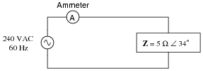
Calculate the line current and power factor in this AC power system:
|
|
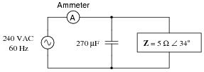
Now, calculate the line current and power factor for the same circuit after the addition of a capacitor in parallel with the load:
|
|
- Without capacitor
- �
- Iline = 48 A
- �
- P.F. = 0.829
- With capacitor
- �
- Iline = 39.87 A
- �
- P.F. = 0.998
Follow-up question: does the addition of the capacitor affect the amount of current through the 5 W load? Why or why not?
Notes:
The answers to this question may seem really strange to students accustomed to DC circuit calculations, where parallel branch currents always add up to a greater total. With complex numbers, however, the sum is not necessarily greater than the individual values!
Question 3:
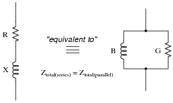
It is often useful in AC circuit analysis to be able to convert a series combination of resistance and reactance into an equivalent parallel combination of conductance and susceptance, or visa-versa:
|
|
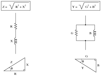
We know that resistance (R), reactance (X), and impedance (Z), as scalar quantities, relate to one another trigonometrically in a series circuit. We also know that conductance (G), susceptance (B), and admittance (Y), as scalar quantities, relate to one another trigonometrically in a parallel circuit:
|
|
If these two circuits are truly equivalent to one another, having the same total impedance, then their representative triangles should be geometrically similar (identical angles, same proportions of side lengths). With equal proportions, R/Z in the series circuit triangle should be the same ratio as G/Y in the parallel circuit triangle, that is R/Z = G/Y.
Building on this proportionality, prove the following equation to be true:
|
After this, derive a similar equation relating the series and parallel reactances (Xseries and Xparallel) with total impedance (Ztotal).
As for the reactance relation equation, here it is:
|
Notes:
Being able to convert between series and parallel AC networks is a valuable skill for analyzing complex series-parallel combination circuits, because it means any series-parallel combination circuit may then be converted into an equivalent simple-series or simple-parallel, which is mush easier to analyze.
Some students might ask why the conductance/susceptance triangle is üpside-down" compared to the resistance/reactance triangle. The reason has to do with the sign reversal of imaginary quantities when inverted: 1/j = -j. The phase angle of a pure inductance's impedance is +90 degrees, while the phase angle of the same (pure) inductance's admittance is -90 degrees, due to reciprocation. Thus, while the X leg of the resistance/reactance triangle points up, the B leg of the conductance/susceptance triangle must point down.
Question 4:
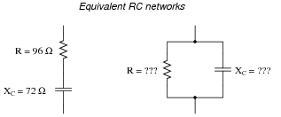
Determine an equivalent parallel RC network for the series RC network shown on the left:
|
|
Note that I have already provided a value for the capacitor's reactance (XC), which of course will be valid only for a particular frequency. Determine what values of resistance (R) and reactance (XC) in the parallel network will yield the exact same total impedance (ZT) at the same signal frequency.
XC = 200 W
Follow-up question: explain how you could check your conversion calculations, to ensure both networks are truly equivalent to each other.
Notes:
This problem just happens to work out with whole numbers. Believe it or not, I chose these numbers entirely by accident one day, when setting up an example problem to show a student how to convert between series and parallel equivalent networks!
Question 5:
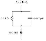
Determine the total impedance of this series-parallel network by first converting it into an equivalent network that is either all-series or all-parallel:
|
|
|
|
Ztotal = 2.638 kW
Notes:
Although there are other methods of solving for total impedance in a circuit such as this, I want students to become comfortable with series/parallel equivalents as an analysis tool.
Question 6:
Determine the equivalent parallel-connected resistor and inductor values for this series circuit:
|
|
Also, express the total impedance of either circuit (since they are electrically equivalent to one another, they should have the same total impedance) in complex form. That is, express Z as a quantity with both a magnitude and an angle.
Lparallel = 1.325 H
Ztotal = 1772 W � 32.14o
Notes:
There are different methods of solving this problem. Use the discussion time to let students expound on how they approached the problem, pooling together their ideas. Their creativity may surprise you!
Question 7:
Determine the equivalent series-connected resistor and capacitor values for this parallel circuit:
|
|
Also, express the total impedance of either circuit (since they are electrically equivalent to one another, they should have the same total impedance) in complex form. That is, express Z as a quantity with both a magnitude and an angle.
Cseries = 3.3 mF
Ztotal = 1066 W � -64.75o
Notes:
There are different methods of solving this problem. Use the discussion time to let students expound on how they approached the problem, pooling together their ideas. Their creativity may surprise you!
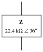
Question 8:
It is not uncommon to see impedances represented in AC circuits as boxes, rather than as combinations of R, L, and/or C. This is simply a convenient way to represent what may be complex sub-networks of components in a larger AC circuit:
|
|
We know that any given impedance may be represented by a simple, two-component circuit: either a resistor and a reactive component connected in series, or a resistor and a reactive component connected in parallel. Assuming a circuit frequency of 250 Hz, determine what combination of series-connected components will be equivalent to this "box" impedance, and also what combination of parallel-connected components will be equivalent to this "box" impedance.
|
|
Notes:
Once students learn to convert between complex impedances, equivalent series R-X circuits, and equivalent parallel R-X circuits, it becomes possible for them to analyze the most complex series-parallel impedance combinations imaginable without having to do arithmetic with complex numbers (magnitudes and angles at every step). It does, however, require that students have a good working knowledge of resistance, conductance, reactance, susceptance, impedance, and admittance, and how these quantities relate mathematically to one another in scalar form.
Question 9:
It is not uncommon to see impedances represented in AC circuits as boxes, rather than as combinations of R, L, and/or C. This is simply a convenient way to represent what may be complex sub-networks of components in a larger AC circuit:
|
|
We know that any given impedance may be represented by a simple, two-component circuit: either a resistor and a reactive component connected in series, or a resistor and a reactive component connected in parallel. Assuming a circuit frequency of 700 Hz, determine what combination of series-connected components will be equivalent to this "box" impedance, and also what combination of parallel-connected components will be equivalent to this "box" impedance.
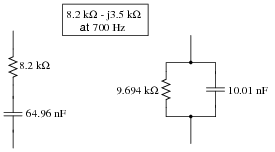
|
|
Notes:
Once students learn to convert between complex impedances, equivalent series R-X circuits, and equivalent parallel R-X circuits, it becomes possible for them to analyze the most complex series-parallel impedance combinations imaginable without having to do arithmetic with complex numbers (magnitudes and angles at every step). It does, however, require that students have a good working knowledge of resistance, conductance, reactance, susceptance, impedance, and admittance, and how these quantities relate mathematically to one another in scalar form.
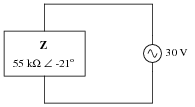
Question 10:
Calculate the amount of current through this impedance, and express your answer in both polar and rectangular forms:
|
|
I = 509.23 mA + j195.47 mA
Follow-up question: which of these two forms is more meaningful when comparing against the indication of an AC ammeter? Explain why.
Notes:
It is important for your students to realize that the two forms given in the answer are really the same quantity, just expressed differently. If it helps, draw a phasor diagram showing how they are equivalent.
This is really nothing more than an exercise in complex number arithmetic. Have your students present their solution methods on the board for all to see, and discuss how Ohm's Law and complex number formats (rectangular versus polar) relate to one another in this question.
Question 11:
Determine the total impedance of this series-parallel network by first converting it into an equivalent network that is either all-series or all-parallel:
|
|
|
|
Ztotal = 4.433 kW
Notes:
Although there are other methods of solving for total impedance in a circuit such as this, I want students to become comfortable with series/parallel equivalents as an analysis tool.
Question 12:
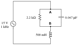
Determine the voltage dropped between points A and B in this circuit:
|
|
Hint: convert the parallel RC sub-network into a series equivalent first.
Notes:
Although there are other ways to calculate this voltage drop, it is good for students to learn the method of series-parallel subcircuit equivalents. If for no other reason, this method has the benefit of requiring less tricky math (no complex numbers needed!).
Have your students explain the procedures they used to find the answer, so that all may benefit from seeing multiple methods of solution and multiple ways of explaining it.
Question 13:
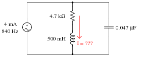
Determine the current through the series LR branch in this series-parallel circuit:
|
|
Hint: convert the series LR sub-network into a parallel equivalent first.
Notes:
Yes, that is an AC current source shown in the schematic! In circuit analysis, it is quite common to have AC current sources representing idealized portions of an actual component. For instance current transformers (CT's) act very close to ideal AC current sources. Transistors in amplifier circuits also act as AC current sources, and are often represented as such for the sake of analyzing amplifier circuits.
Although there are other ways to calculate this voltage drop, it is good for students to learn the method of series-parallel subcircuit equivalents. If for no other reason, this method has the benefit of requiring less tricky math (no complex numbers needed!).
Have your students explain the procedures they used to find the answer, so that all may benefit from seeing multiple methods of solution and multiple ways of explaining it.
Question 14:
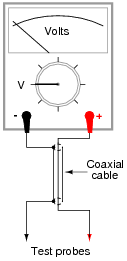
Test leads for DC voltmeters are usually just two individual lengths of wire connecting the meter to a pair of probes. For highly sensitive instruments, a special type of two-conductor cable called coaxial cable is generally used instead of two individual wires. Coaxial cable - where a center conductor is ßhielded" by an outer braid or foil that serves as the other conductor - has excellent immunity to induced "noise" from electric and magnetic fields:
|
|
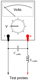
When measuring high-frequency AC voltages, however, the parasitic capacitance and inductance of the coaxial cable may present problems. We may represent these distributed characteristics of the cable as "lumped" parameters: a single capacitor and a single inductor modeling the cable's behavior:
|
|
Typical parasitic values for a 10-foot cable would be 260 pF of capacitance and 650 mH of inductance. The voltmeter itself, of course, is not without its own inherent impedances, either. For the sake of this example, let's consider the meter's ïnput impedance" to be a simple resistance of 1 MW.
Calculate what voltage the meter would register when measuring the output of a 20 volt AC source, at these frequencies:
- �
- f = 1 Hz ; Vmeter =
- �
- f = 1 kHz ; Vmeter =
- �
- f = 10 kHz ; Vmeter =
- �
- f = 100 kHz ; Vmeter =
- �
- f = 1 MHz ; Vmeter =
- �
- f = 1 Hz ; Vmeter = 20 V
- �
- f = 1 kHz ; Vmeter = 20 V
- �
- f = 10 kHz ; Vmeter = 20.01 V
- �
- f = 100 kHz ; Vmeter = 21.43 V
- �
- f = 1 MHz ; Vmeter = 3.526 V
Follow-up question: explain why we see a "peak" at 100 kHz. How can the meter possibly see a voltage greater than the source voltage (20 V) at this frequency?
Notes:
As your students what this indicates about the use of coaxial test cable for AC voltmeters. Does it mean that coaxial test cable is unusable for any measurement application, or may we use it with little or no concern in some applications? If so, which applications are these?
Question 15:
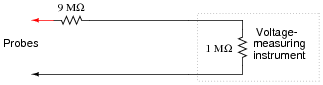
The voltage measurement range of a DC instrument may easily be ëxtended" by connecting an appropriately sized resistor in series with one of its test leads:
|
|
In the example shown here, the multiplication ratio with the 9 MW resistor in place is 10:1, meaning that an indication of 3.5 volts at the instrument corresponds to an actual measured voltage of 35 volts between the probes.
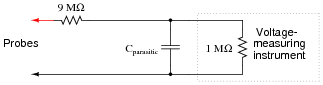
While this technique works very well when measuring DC voltage, it does not do so well when measuring AC voltage, due to the parasitic capacitance of the cable connecting the test probes to the instrument (parasitic cable inductance has been omitted from this diagram for simplicity):
|
|
To see the effects of this capacitance for yourself, calculate the voltage at the instrument input terminals assuming a parasitic capacitance of 180 pF and an AC voltage source of 10 volts, for the following frequencies:
- �
- f = 10 Hz ; Vinstrument =
- �
- f = 1 kHz ; Vinstrument =
- �
- f = 10 kHz ; Vinstrument =
- �
- f = 100 kHz ; Vinstrument =
- �
- f = 1 MHz ; Vinstrument =
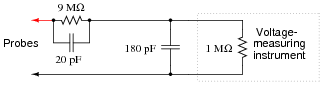
The debilitating effect of cable capacitance may be compensated for with the addition of another capacitor, connected in parallel with the 9 MW range resistor. If we are trying to maintain a voltage division ratio of 10:1, this "compensating" capacitor must be 1/9 the value of the capacitance parallel to the instrument input:
|
|
Re-calculate the voltage at the instrument input terminals with this compensating capacitor in place. You should notice quite a difference in instrument voltages across this frequency range!
- �
- f = 10 Hz ; Vinstrument =
- �
- f = 1 kHz ; Vinstrument =
- �
- f = 10 kHz ; Vinstrument =
- �
- f = 100 kHz ; Vinstrument =
- �
- f = 1 MHz ; Vinstrument =
Complete your answer by explaining why the compensation capacitor is able to "flatten" the response of the instrument over a wide frequency range.
- �
- f = 10 Hz ; Vinstrument = 1.00 V
- �
- f = 1 kHz ; Vinstrument = 0.701 V
- �
- f = 10 kHz ; Vinstrument = 97.8 mV
- �
- f = 100 kHz ; Vinstrument = 9.82 mV
- �
- f = 1 MHz ; Vinstrument = 0.982 mV
With the 20 pF compensating capacitor in place:
- �
- f = 10 Hz ; Vinstrument = 1.00 V
- �
- f = 1 kHz ; Vinstrument = 1.00 V
- �
- f = 10 kHz ; Vinstrument = 1.00 V
- �
- f = 100 kHz ; Vinstrument = 1.00 V
- �
- f = 1 MHz ; Vinstrument = 1.00 V
Hint: without the compensating capacitor, the circuit is a resistive voltage divider with a capacitive load. With the compensating capacitor, the circuit is a parallel set of equivalent voltage dividers, effectively eliminating the loading effect.
Follow-up question: as you can see, the presence of a compensation capacitor is not an option for a high-frequency, 10:1 oscilloscope probe. What safety hazard(s) might arise if a probe's compensation capacitor failed in such a way that the probe behaved as if the capacitor were not there at all?
Notes:
Explain to your students that "×10" oscilloscope probes are made like this, and that the "compensation" capacitor in these probes is usually made adjustable to create a precise 9:1 match with the combined parasitic capacitance of the cable and oscilloscope.
Ask your students what the usable "bandwidth" of a home-made ×10 oscilloscope probe would be if it had no compensating capacitor in it.
Question 16:
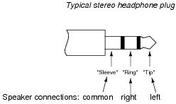
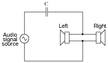
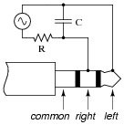
Stereo (two-speaker) headphones typically use a plug with three contact points to connect the speakers to the audio amplifier. The three contact points are designated as "tip," "ring," and ßleeve" for reasons that are obvious upon inspection, and as such the plug is commonly referred to as a "TRS" plug. Both speakers in the headphone unit share a common connection (at the ßleeve" contact), with the "tip" and "ring" contacts providing connection to left and right speakers, respectively:
|
|
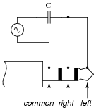
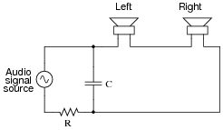
Draw a picture showing how connections would be made to the plug's contact points to form this circuit:
|
|
|
|
Notes:
This question challenges students to determine what "common" means, in relation to the speaker connections. Also, it requires that they translate the nice, clean schematic diagram into a real-world illustration, which is a difficult task for some (but well worth the time to practice!).
Question 17:
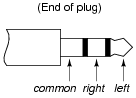
Stereo (two-speaker) headphones typically use a plug with three contact points to connect the speakers to the audio amplifier. The three contact points are designated as "tip," "ring," and ßleeve" for reasons that are obvious upon inspection, and as such the plug is commonly referred to as a "TRS" plug. Both speakers in the headphone unit share a common connection (at the ßleeve" contact), with the "tip" and "ring" contacts providing connection to left and right speakers, respectively:
|
|
Draw a picture showing how connections would be made to the plug's contact points to form this circuit:
|
|
|
|
Notes:
This question challenges students to determine what "common" means, in relation to the speaker connections. Also, it requires that they translate the nice, clean schematic diagram into a real-world illustration, which is a difficult task for some (but well worth the time to practice!).
Question 18:
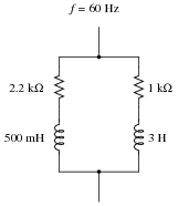
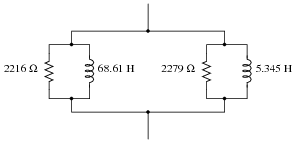
Convert this series-parallel combination circuit into an equivalent simple-parallel circuit (all components connected in parallel with each other, with nothing in series), and also calculate the circuit's total impedance:
|
|
|
|
Ztotal = 963.0 W
Challenge question: from the simple-parallel equivalent circuit shown here, can you generate an equivalent circuit that is simple-series? In other words, can you calculate the proper values of R and L, that when connected in series, will have the same total impedance as this circuit?
Notes:
Fundamentally, this question asks students to generate an equivalent parallel R-X circuit from a given series R-X circuit. In this particular circuit, there are two series-connected R-X branches, resulting in an equivalent parallel circuit with four branches.
Calculating the circuit's total impedance as a scalar figure involves simplifying the circuit once more into two components: a resistance and a reactance.
Question 19:
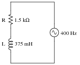
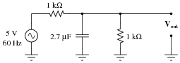
Calculate the öutput" voltage (Vout) for this AC circuit, expressed as a complex quantity in polar notation:
|
|
Notes:
Discuss with your students what a good procedure might be for calculating the unknown values in this problem, and also how they might check their work.
Students often have difficulty formulating a method of solution: determining what steps to take to get from the given conditions to a final answer. While it is helpful at first for you (the instructor) to show them, it is bad for you to show them too often, lest they stop thinking for themselves and merely follow your lead. A teaching technique I have found very helpful is to have students come up to the board (alone or in teams) in front of class to write their problem-solving strategies for all the others to see. They don't have to actually do the math, but rather outline the steps they would take, in the order they would take them.
By having students outline their problem-solving strategies, everyone gets an opportunity to see multiple methods of solution, and you (the instructor) get to see how (and if!) your students are thinking. An especially good point to emphasize in these öpen thinking" activities is how to check your work to see if any mistakes were made.
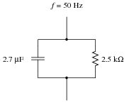
Question 20:
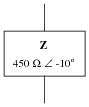
It is not uncommon to see impedances represented in AC circuits as boxes, rather than as combinations of R, L, and/or C. This is simply a convenient way to represent what may be complex sub-networks of components in a larger AC circuit:
|
|
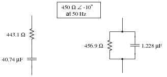
We know that any given impedance may be represented by a simple, two-component circuit: either a resistor and a reactive component connected in series, or a resistor and a reactive component connected in parallel. Assuming a circuit frequency of 50 Hz, determine what combination of series-connected components will be equivalent to this "box" impedance, and also what combination of parallel-connected components will be equivalent to this "box" impedance.
|
|
Notes:
Once students learn to convert between complex impedances, equivalent series R-X circuits, and equivalent parallel R-X circuits, it becomes possible for them to analyze the most complex series-parallel impedance combinations imaginable without having to do arithmetic with complex numbers (magnitudes and angles at every step). It does, however, require that students have a good working knowledge of resistance, conductance, reactance, susceptance, impedance, and admittance, and how these quantities relate mathematically to one another in scalar form.
Question 21:
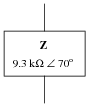
It is not uncommon to see impedances represented in AC circuits as boxes, rather than as combinations of R, L, and/or C. This is simply a convenient way to represent what may be complex sub-networks of components in a larger AC circuit:
|
|
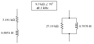
We know that any given impedance may be represented by a simple, two-component circuit: either a resistor and a reactive component connected in series, or a resistor and a reactive component connected in parallel. Assuming a circuit frequency of 2 kHz, determine what combination of series-connected components will be equivalent to this "box" impedance, and also what combination of parallel-connected components will be equivalent to this "box" impedance.
|
|
Notes:
Once students learn to convert between complex impedances, equivalent series R-X circuits, and equivalent parallel R-X circuits, it becomes possible for them to analyze the most complex series-parallel impedance combinations imaginable without having to do arithmetic with complex numbers (magnitudes and angles at every step). It does, however, require that students have a good working knowledge of resistance, conductance, reactance, susceptance, impedance, and admittance, and how these quantities relate mathematically to one another in scalar form.
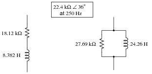
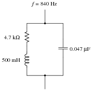
Question 22:
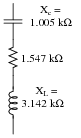
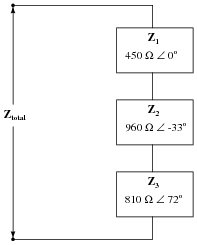
Calculate the total impedance of this series network of impedances, in complex form:
|
|
Follow-up question: overall, does this network behave more like a capacitor, an inductor, or a resistor? Explain your answer.
Notes:
Students should find series impedance calculations very similar to series (DC) resistance calculations, the only significant difference being the use of complex instead of scalar numbers.
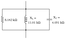
Question 23:
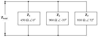
Calculate the total impedance of this parallel network of impedances, in complex form:
|
|
Follow-up question: overall, does this network behave more like a capacitor, an inductor, or a resistor? Explain your answer.
Notes:
Students should find parallel impedance calculations very similar to parallel (DC) resistance calculations, the only significant difference being the use of complex instead of scalar numbers. This makes parallel impedance calculations difficult, no doubt about it. Attaining a solution for this problem will involve a lot of arithmetic, with lots of room for calculation error.
Question 24:
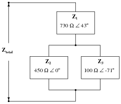
Calculate the total impedance of this series-parallel network of impedances, in complex form:
|
|
Follow-up question: overall, does this network behave more like a capacitor, an inductor, or a resistor? Explain your answer.
Notes:
Students should find parallel impedance calculations very similar to parallel (DC) resistance calculations, the only significant difference being the use of complex instead of scalar numbers. This makes parallel impedance calculations difficult, no doubt about it. Attaining a solution for this problem will involve a lot of arithmetic, with lots of room for calculation error.
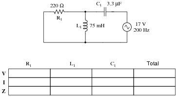
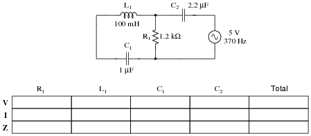
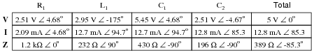
Question 25:
Complete the table of values for this circuit, representing all quantities in complex-number form:
|
|
|
|
Notes:
Students often have difficulty formulating a method of solution: determining what steps to take to get from the given conditions to a final answer. While it is helpful at first for you (the instructor) to show them, it is bad for you to show them too often, lest they stop thinking for themselves and merely follow your lead. A teaching technique I have found very helpful is to have students come up to the board (alone or in teams) in front of class to write their problem-solving strategies for all the others to see. They don't have to actually do the math, but rather outline the steps they would take, in the order they would take them. The following is a sample of a written problem-solving strategy for analyzing a series resistive-reactive AC circuit:
Step 1: Calculate all reactances (X).
Step 2: Draw an impedance triangle (Z ; R ; X), solving for Z
Step 3: Calculate circuit current using Ohm's Law: I = V/Z
Step 4: Calculate series voltage drops using Ohm's Law: V = I Z
Step 5: Check work by drawing a voltage triangle (Vtotal ; V1 ; V2), solving for Vtotal
By having students outline their problem-solving strategies, everyone gets an opportunity to see multiple methods of solution, and you (the instructor) get to see how (and if!) your students are thinking. An especially good point to emphasize in these öpen thinking" activities is how to check your work to see if any mistakes were made.
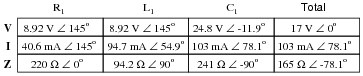
Question 26:
Complete the table of values for this circuit, representing all quantities in complex-number form:
|
|
|
|
Notes:
Students often have difficulty formulating a method of solution: determining what steps to take to get from the given conditions to a final answer. While it is helpful at first for you (the instructor) to show them, it is bad for you to show them too often, lest they stop thinking for themselves and merely follow your lead. A teaching technique I have found very helpful is to have students come up to the board (alone or in teams) in front of class to write their problem-solving strategies for all the others to see. They don't have to actually do the math, but rather outline the steps they would take, in the order they would take them. The following is a sample of a written problem-solving strategy for analyzing a series resistive-reactive AC circuit:
Step 1: Calculate all reactances (X).
Step 2: Draw an impedance triangle (Z ; R ; X), solving for Z
Step 3: Calculate circuit current using Ohm's Law: I = V/Z
Step 4: Calculate series voltage drops using Ohm's Law: V = I Z
Step 5: Check work by drawing a voltage triangle (Vtotal ; V1 ; V2), solving for Vtotal
By having students outline their problem-solving strategies, everyone gets an opportunity to see multiple methods of solution, and you (the instructor) get to see how (and if!) your students are thinking. An especially good point to emphasize in these öpen thinking" activities is how to check your work to see if any mistakes were made.