AC generator theory
Question 1:
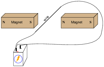
If an electric current is passed through this wire, which direction will the wire be pushed (by the interaction of the magnetic fields)?
|
|
Is this an example of an electric motor or an electric generator?
Notes:
A visual aid to understanding the interaction of the two magnetic fields is a diagram showing the lines of flux emanating from the permanent magnets, against the circular lines of flux around the wire. Ask those students who came across similar illustrations in their research to draw a picture of this on the board in front of the class, for those who have not seen it.
Question 2:
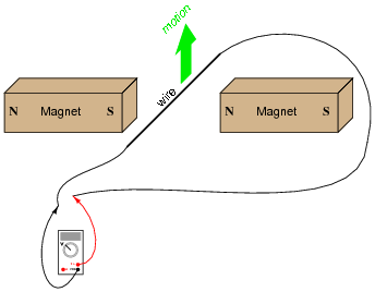
If this wire (between the magnet poles) is moved in an upward direction, what polarity of voltage will the meter indicate?
|
|
Describe the factors influencing the magnitude of the voltage induced by motion, and determine whether this is an example of an electric motor or an electric generator.
Notes:
Ask your students to explain their answers regarding factors that influence voltage magnitude. Where did they obtain their information? Are there any mathematical formulae relating these factors to induced voltage?
Question 3:
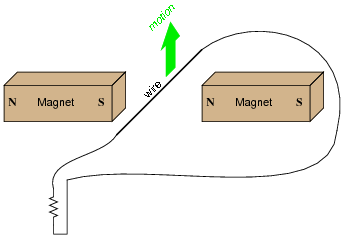
If this wire (between the magnet poles) is moved in an upward direction, and the wire ends are connected to a resistive load, which way will current go through the wire?
|
|
We know that current moving through a wire will create a magnetic field, and that this magnetic field will produce a reaction force against the static magnetic fields coming from the two permanent magnets. Which direction will this reaction force push the current-carrying wire? How does the direction of this force relate to the direction of the wire's motion? Does this phenomenon relate to any principle of electromagnetism you've learned so far?
Follow-up question: What does this phenomenon indicate to us about the ease of moving a generator mechanism under load, versus unloaded? What effect does placing an electrical load on the output terminals of a generator have on the mechanical effort needed to turn the generator?
Notes:
If you happen to have a large, permanent magnet DC motor available in your classroom, you may easily demonstrate this principle for your students. Just have them spin the shaft of the motor (generator) with their hands, with the power terminals open versus shorted together. Your students will notice a huge difference in the ease of turning between these two states.
After your students have had the opportunity to discuss this phenomenon and/or experience it themselves, ask them why electromechanical meter movement manufacturers usually ship meters with a shorting wire connecting the two meter terminals together. In what way does a PMMC meter movement resemble an electric generator? How does shorting the terminals together help to protect against damage from physical vibration during shipping?
Ask your students to describe what factors influence the magnitude of this reaction force.
Question 4:
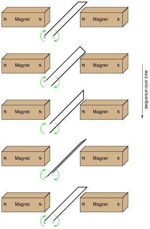
Determine the polarity of induced voltage between the ends of this wire loop, as it is rotated between the two magnets:

|
|
|
|
Challenge question: if a resistor were connected between the ends of this wire loop, would it ßee" direct current (DC), or alternating current (AC)?
Notes:
Note that the two wire ends switch polarity as the loop rotates. Ask your students to explain why the polarities are as they are.
Question 5:
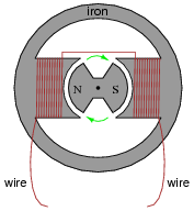
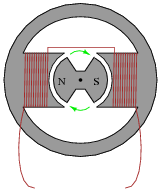
Describe the nature of the voltage induced in the stationary (ßtator") windings, as the permanent magnet rotor rotates in this machine:
|
|
What factors determine the magnitude of this voltage? According to Faraday's Law, what factors can we alter to increase the voltage output by this generator?
Is the induced voltage AC or DC? How can you tell?
Follow-up question: AC generators, or alternators as they are sometimes called, are typically long-lived machines when operated under proper conditions. But like all machines, they will eventually fail. Based on the illustration given in the question, identify some probable modes of failure for an alternator, and what conditions might hasten such failures.
Notes:
Ask your students to write the equation for Faraday's Law on the whiteboard, and then analyze it in a qualitative sense (with variables increasing or decreasing in value) to validate the answers.
The first answer to this question (increase [(df)/dt]) has been left purposefully vague, in order to make students think. What, specifically, must be changed in order to increase this rate-of-change over time? Which real-world variables are changeable after the generator has been manufactured, and which are not?
Question 6:
In order to make the most practical AC generator (or alternator, as it is also known), which design makes more sense: a stationary permanent magnet with a rotating wire coil, or a rotating permanent magnet with a stationary wire coil? Explain your choice.
Follow-up question: what is so bad about brushes and slip rings that we want to avoid them in alternator design if possible?
Notes:
Answering the follow-up question may require a bit of research on the part of your students. Ask them to describe what "brushes" are and what ßlip rings" are, and then the mechanical wearing aspects of these parts should become plain.
Question 7:
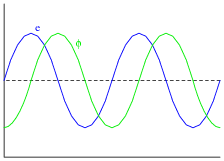
We know that in order to induce a sinusoidal voltage in a wire coil, the magnetic flux linking the turns of wire in the coil must follow a sinusoidal path over time, phase-shifted 90o from the voltage waveform. This relationship between flux and induced voltage is expressed in Faraday's equation v = N [(df)/dt]:
|
|
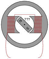
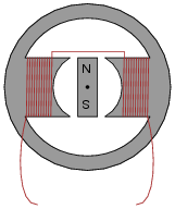
Based on this fact, draw the position of the magnetic rotor in this alternator when the voltage is at one of its peaks:
|
|
|
|
(The actual magnet polarities are not essential to the answer. Without knowing which way the coils were wound and which way the rotor is spinning, it is impossible to specify an exact magnetic polarity, so if your answer had "N" facing down and "S" facing up, it's still acceptable.)
Notes:
This question challenges students to relate the magnetic flux waveform (f) to an instantaneous rotor position. The answer may come as a surprise to some, who expected maximum induced voltage to occur when the rotor is in-line with the stator poles. This answer, however, makes the mistake of confusing flux (f) with rate-of-flux-change over time ([(df)/dt]). A rotor lined up with the stator poles would result in maximum flux (f) through those poles, but not maximum rate-of-flux-change over time ([(df)/dt]).
Question 8:
If this alternator is spun at 4500 RPM (revolutions per minute), what will be the frequency of its output voltage?
|
|
Hint: how many cycles of AC are produced for every revolution of the rotor?
Notes:
Students should realize that there is one cycle of AC voltage produced for every revolution of the rotor shaft. From that point, the problem is simply a matter of unit conversions.
Question 9:
How fast must a 12-pole alternator spin in order to produce 60 Hz AC power? Write a mathematical equation solving for speed (S) in terms of frequency (f) and the number of poles (N).
|
Follow-up question: algebraically manipulate this equation to solve for the number of poles (N) needed in a generator given speed (S) and frequency (f).
Notes:
This may be especially confusing to some students, until they realize that alternator poles are always multiples of 2 (the simplest alternator having 2 poles).
Question 10:
How many poles does an alternator have if it generates 400 Hz power at a shaft speed of 6000 RPM?
Follow-up question: algebraically manipulate the speed/poles/frequency equation to solve for the frequency generated (f) given the number of poles (N) and the generator speed (S).
Notes:
Some references provide equations in terms of pole pairs instead of individual alternator poles.
Question 11:
Assuming that the output frequency of an alternator must remain constant (as is the case in national power systems, where the frequency of all power plants must be the same), how may its output voltage be regulated? In other words, since we do not have the luxury of increasing or decreasing its rotational speed to control voltage, since that would change the frequency, how can we coax the alternator to produce more or less voltage on demand?
Hint: automotive alternators are manufactured with this feature, though the purpose in that application is to maintain constant voltage despite changes in engine speed. In automotive electrical systems, the frequency of the alternator's output is irrelevant because the AC is "rectified" into DC (frequency = 0 Hz) to charge the battery.
Follow-up question: how is it possible to conduct electric power to windings on a spinning rotor? Should we energize the rotor winding with AC or DC? Explain your answer.
Notes:
Ask your students how this voltage regulation strategy compares with that of DC generators. Ask them to describe the difference between "commutator bars" and ßlip rings."
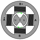
Question 12:
Suppose we have an alternator with two sets of windings, A and B:
|
|
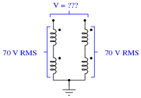
Each pair of windings in each set is series-connected, so they act as just two separate windings:

|
|
If one end of each winding pair were connected together at a common ground point, and each winding pair output 70 volts RMS, how much voltage would be measured between the open winding pair ends?
|
|
Hint: if you don't understand how this voltage value was calculated, plot the voltage output of the two windings as if they were shown on an oscilloscope. The phase relationship between the two voltages is key to the solution.
Follow-up question: draw a phasor diagram showing how the difference in potential (voltage) between the wire ends is equal to 99 volts, when each winding coil's voltage is 70 volts.
Notes:
This question is a good exercise of students' knowledge of phase shift, in a very practical context.
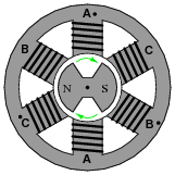
Question 13:
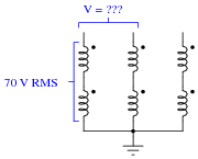
Suppose we have an alternator with three sets of windings, A, B, and C:
|
|
Each pair of windings in each set is series-connected, so they act as just three separate windings (pay close attention to the phase-marking dots!):
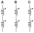
|
|
If one end of each winding pair were connected together at a common ground point, and each winding pair output 70 volts RMS, how much voltage would be measured between any two open wires?
|
|
Follow-up question: draw a phasor diagram showing how the difference in potential (voltage) between the wire ends is equal to 121.2 volts, when each winding coil's voltage is 70 volts.
Notes:
This question is a good exercise of students' knowledge of phase shift, in a very practical context.