AC metrology
Question 1:
In power distribution systems, it is very important to be able to measure line voltage. You cannot control what you cannot measure, and it is important to control power line voltage so as to not exceed the insulators' ratings.
But how do you safely measure the voltage of a 750 kV power line? Obviously, no voltmeter small enough to be located on a control panel could safely handle 750,000 volts applied to it, as a voltage that high is capable of arcing several feet through the air (not to mention the safety hazards of having wires behind the meter panel connecting straight to the power line!).
In industry, specialized transformers are used to safely measure the high voltages on power lines. Describe what is special about these "potential transformers," and how they are implemented to measure dangerous voltages.
Follow-up question: in addition to stepping the line voltage down to relatively safe levels, potential transformers also provide one more important safety feature for voltage measurement. Describe what this extra feature is, and why it is important. Hint: all transformers except for autotransformers provide this feature!
Notes:
Ask students to draw a rough schematic diagram of how a potential transformer would be placed in a complete voltage-measurement circuit, with power lines, panel-mounted voltmeter mechanism, safety fuses, etc.
Question 2:
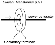
A common instrument used for measuring high AC currents in power systems is a current transformer, abbreviated "CT". Current transformers usually take the form of a "donut," through which the current-carrying conductor passes:
|
|
The purpose of a current transformer is to create a secondary current that is a precise fraction of the primary current, for easier measurement of current in the power conductor.
Given this function, would current transformers be considered a ßtep-up" or ßtep-down" transformer? Also, draw how the secondary windings of a current transformer are arranged around its toroidal core.
Notes:
The question of whether the current transformer is a ßtep-down" or ßtep-up" has an important safety implication for students to realize. Ask your students to describe what conditions might prove the most dangerous when working around current transformers, given their ßtep-up" nature with reference to voltage.
Question 3:
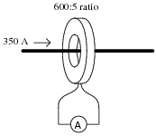
How much current will be output by a current transformer if the load current is 350 amps and the CT ratio is 600:5?
|
|
Notes:
This question is an exercise in mathematical ratios.
Question 4:
It is very important that the secondary winding of a current transformer (CT) never be open-circuited while in operation! Explain why this is an important safety consideration.
Notes:
There are a couple of different ways to explain why current transformers pose this safety hazard. One could explain it in terms of the winding ratio, or perhaps in terms of its function as an AC "current source". Do not be surprised if your students present multiple explanations for this behavior.
Question 5:
Suppose you wished to measure the current of an AC motor, the full-load current of which should be about 150 amps. This current is much too great to measure directly with your only AC ammeter (rated 0 to 5 amps), and the only current transformers you have available are rated at 1200:5, which would not produce enough output current to drive the 0-5 amp meter movement very far at a load current of 150 amps. Sure, you would get a measurement, but it wouldn't be very accurate.
Figure out a way to overcome this measurement problem, so that a motor current of 150 amps will produce a more substantial deflection on the 0-5 amp meter movement scale.
Notes:
The "multiple wrap" solution is a neat trick I've used more than once to measure current with an oversized current transformer. Discuss the effect of multiple "turns" of primary conductor on the ratio of a CT with your students, calculating the new ratios formed by doing so.
Although the "multiple wrap" solution is simple, it is not the only possible solution to this problem. Another solution would be to use multiple current transformers, but I'll leave that up to you and your students to figure out!
Question 6:
Describe the purpose of a current transformer in an AC power circuit.
Notes:
Ask your students to describe the physical appearance and construction of a CT. If possible, bring one in to your classroom for viewing and discussion.
Question 7:
What does it mean if a meter movement is described as being RMS indicating, average responding?
Challenge question: if one of these meters is subjected to a square-wave AC signal, will its "RMS" indication be falsely low, falsely high, or accurate?
Notes:
This concept is confusing to many students, yet important for them to understand. I suggest you illuminate the subject by asking a series of questions:
- �
- What would one of these meters indicate if the amplitude of a sinusoidal signal were doubled? Answer: the indication would double.
- �
- What would one of these meters indicate if the signal amplitude and wave-shape were to change in such a way that the average value of the signal doubled, but the RMS value did not increase as much? Answer: the indication would double.
- �
- What would one of these meters indicate if the signal amplitude and wave-shape were to change in such a way that the RMS value of the signal doubled, but the average value did not increase as much? Answer: the indication would increase only as much as the average value increased.
Question 8:
Electrostatic meter movements use the physical attraction between metal plates caused by a voltage to deflect a pointer, instead of using electromagnetism as is common with most other meter movement designs. Although electrostatic meter movements are not as sensitive as PMMC mechanisms, they have the advantage of being able to measure both AC and DC with equal ease.
Suppose you calibrated an electrostatic meter movement from 0 volts to 500 volts DC. Then, you connected this meter to a sinusoidal AC source and watched it register a voltage of 216 volts. What is the voltage of this AC source, in volts RMS?
Hint: most mechanical meter movements naturally indicate the average value of an AC waveform!
Notes:
Discuss with your students the reason why most meter movements function on the average value of an AC waveform. Why don't meter movement naturally indicate RMS value? Ask your students how äverage" and "RMS" AC values are defined, and what physical systems represent these mathematical models.
Question 9:
Most electromechanical meter movements are inherently average-responding. They display their indications in units of volts or amps "RMS" only because they have been calibrated to do so for sinusoidal waveforms.
Some electromechanical meter movements, though, are true-RMS responding. For example, electrodynamometer movements, when connected as either voltmeters or ammeters (not as wattmeters), naturally provide indications proportional to the voltage's or current's true RMS value.
Based on the inherent differences between these meter movements, describe how you could use electromechanical meter movements to perform qualitative assessments of waveform distortion. In other words, how could you use electromechanical meters to tell whether an AC waveform was sinusoidal or not?
Notes:
Given the prevalence of harmonics in modern AC power systems, this "trick" can be quite useful in making qualitative assessments of harmonic distortion. Of course, expensive test equipment will give quantitative measurements of distortion, but it's always nice to know how to use lesser test equipment just in case the expensive equipment is not available.
Question 10:
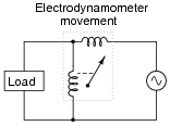
An electromechanical meter movement commonly used to measure AC power is called the electrodynamometer movement. Describe how this meter works, and draw a schematic diagram showing how it is used to measure the AC power delivered to a load.
Question 11:
There is a lot of incorrect terminology and information in the world of high-fidelity audio equipment, due primarily to a large consumer base lacking technical knowledge. One of the common mis-statements of audio amplifier performance is power, expressed in "watts peak" and "watts RMS". While the term "peak power" is not necessarily incorrect, "RMS power" most definitely is. What is wrong with the latter term, and what do you think audio equipment manufacturers mean when they specify an amplifier's power rating in "watts RMS"?
Notes:
Having dispensed with the oxymoronic notion of "RMS power," we now proceed to the next question: what do amplifier manufacturers mean by this rating? Your students should have done some research on amplifier power ratings, and seen what the manufacturers say about them. Based on that research, what do your students think the manufacturers are trying to state when they talk about "RMS power"? Is there a better way to say this?