AC motor theory
Question 1:
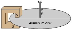
Electromechanical watt-hour meters use an aluminum disk that is spun by an electric motor. To generate a constant "drag" on the disk necessary to limit its rotational speed, a strong magnet is placed in such a way that its lines of magnetic flux pass perpendicularly through the disk's thickness:
|
|
The disk itself need not be made of a ferromagnetic material in order for the magnet to create a "drag" force. It simply needs to be a good conductor of electricity.
Explain the phenomenon accounting for the drag effect, and also explain what would happen if the roles of magnet and disk were reversed: if the magnet were moved in a circle around the periphery of a stationary disk.
Notes:
Mechanical speedometer assemblies used on many automobiles use this very principle: a magnet assembly is rotated by a cable connected to the vehicle's driveshaft. This magnet rotates in close proximity to a metal disk, which gets "dragged" in the same direction that the magnet spins. The disk's torque acts against the resistance of a spring, deflecting a pointer along a scale, indicating the speed of the vehicle. The faster the magnet spins, the more torque is felt by the disk.
Question 2:
Explain what will happen to the unmagnetized rotor when 3-phase AC power is applied to the stationary electromagnet coils. Note that the rotor is actually a short-circuited electromagnet:
|
|
Follow-up question: what would happen if the rotor's coil were to become open-circuited?
Notes:
Here, we see a practical 3-phase induction motor. Be sure to thoroughly discuss what is necessary to increase or decrease rotor speed, and compare this with what is necessary to increase or decrease speed in a DC motor.
Question 3:
Explain what slip speed is for an AC induction motor, and why there must be such as thing as ßlip" in order for an induction motor to generate torque.
Notes:
It is easy enough for students to research ßlip speed" in any motor reference book and present a definition. It is quite another for them to explain why slip is necessary. Be sure to allow ample time in class to discuss this concept, because it is at the heart of induction motor operation.
Question 4:
A very common design of AC motor is the so-called squirrel cage motor. Describe how a ßquirrel cage" motor is built, and classify it as either an ïnduction" motor or a ßynchronous" motor.
Notes:
Although it is easy enough for students to find information on squirrel cage motors classifying them as either induction or synchronous, you should challenge your students to explain why it is one type or the other. The goal here, as always, is comprehension over memorization.
Question 5:
What would we have to do in order to reverse the rotation of this three-phase induction motor?
|
|
Explain your answer. Describe how the (simple) solution to this problem works.
Notes:
One of the reasons three-phase motors are preferred in industry is the simplicity of rotation reversal. However, this is also a problem because when you connect a three-phase motor to its power source during maintenance or installation procedures, you often do not know which way it will rotate until you turn the power on!
Discuss with your students how an electrician might go about his or her job when installing a three-phase motor. What would be the proper lock-out/tag-out sequence, and steps to take when connecting a motor to its power source? What would have to be done if it is found the motor rotates in the wrong direction?
Question 6:
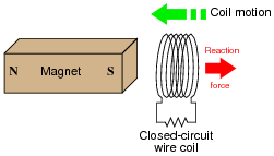
If a copper ring is brought closer to the end of a permanent magnet, a repulsive force will develop between the magnet and the ring. This force will cease, however, when the ring stops moving. What is this effect called?
|
|
Also, describe what will happen if the copper ring is moved away from the end of the permanent magnet.
Follow-up question: trace the direction of rotation for the induced electric current in the ring necessary to produce both the repulsive and the attractive force.
Challenge question: what would happen if the magnet's orientation were reversed (south pole on left and north pole on right)?
Notes:
This phenomenon is difficult to demonstrate without a very powerful magnet. However, if you have such apparatus available in your lab area, it would make a great piece for demonstration!
One practical way I've demonstrated Lenz's Law is to obtain a rare-earth magnet (very powerful!), set it pole-up on a table, then drop an aluminum coin (such as a Japanese Yen) so it lands on top of the magnet. If the magnet is strong enough and the coin is light enough, the coin will gently come to rest on the magnet rather than hit hard and bounce off.
A more dramatic illustration of Lenz's Law is to take the same coin and spin it (on edge) on a table surface. Then, bring the magnet close to the edge of the spinning coin, and watch the coin promptly come to a halt, without contact between the coin and magnet.
Another illustration is to set the aluminum coin on a smooth table surface, then quickly move the magnet over the coin, parallel to the table surface. If the magnet is close enough, the coin will be "dragged" a short distance as the magnet passes over.
In all these demonstrations, it is significant to show to your students that the coin itself is not magnetic. It will not stick to the magnet as an iron or steel coin would, thus any force generated between the coin and magnet is strictly due to induced currents and not ferromagnetism.
Question 7:
A technique commonly used in special-effects lighting is to sequence the on/off blinking of a string of light bulbs, to produce the effect of motion without any moving objects:
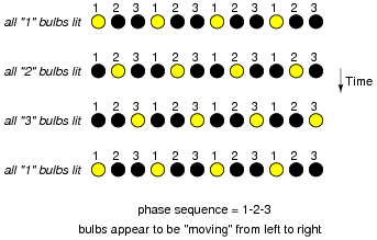
|
|
What would the effect be if this string of lights were arranged in a circle instead of a line? Also, explain what would have to change electrically to alter the ßpeed" of the blinking lights' "motion".
Follow-up question: what electrical change(s) would you have to make to reverse the direction of the lights' apparent motion?
Challenge question: what would happen to the apparent motion of the lights if one of the phases (either 1, 2, or 3) were to fail, so that none of the bulbs with that number would ever light up?
Notes:
Ask your students to describe what would happen to the blinking lights if the voltage were increased or decreased. Would this alter the perceived speed of motion?
Although this question may seem insultingly simple to many, its purpose is to introduce other sequenced-based phenomenon such as polyphase electric motor theory, where the answers to analogous questions are not so obvious.
Question 8:
If a set of six electromagnet coils were spaced around the periphery of a circle and energized by 3-phase AC power, what would a magnetic compass do that was placed in the center?
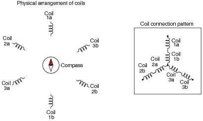
|
|
Hint: imagine the electromagnets were light bulbs instead, and the frequency of the AC power was slow enough to see each light bulb cycle in brightness, from fully dark to fully bright and back again. What would the pattern of lights appear to do?
Challenge question: what would happen to the apparent motion of the magnetic field if one of the phases (either 1, 2, or 3) were to fail, so that none of the coils with that number would ever energize?
Notes:
The concept of the rotating magnetic field is central to AC motor theory, so it is imperative that students grasp this concept before moving on to more advanced concepts. If you happen to have a string of blinking "Christmas lights" to use as a prop in illustrating a rotating magnetic field, this would be a good thing to show your students during discussion time.
Question 9:
Explain what will happen to the magnetized rotor when 3-phase AC power is applied to the stationary electromagnet coils:
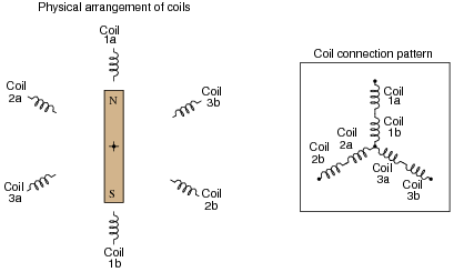
|
|
Follow-up question: what must we do with the AC power energizing the coils to increase the rotor's rotational speed?
Notes:
Here, we see a practical 3-phase electric motor. Be sure to thoroughly discuss what is necessary to increase or decrease rotor speed, and compare this with what is necessary to increase or decrease speed in a DC motor.
Question 10:
If a closed-circuit wire coil is brought closer to the end of a permanent magnet, a repulsive force will develop between the magnet and the coil. This force will cease, however, when the coil stops moving. What is this effect called?
|
|
Also, describe what will happen if the wire coil fails open. Does the same effect persist? Why or why not?
Notes:
The phenomenon of Lenz's Law is usually showcased using a metal solid such as a disk or ring, rather than a wire coil, but the phenomenon is the same.
Question 11:
Describe what will happen to a closed-circuit wire coil if it is placed in close proximity to an electromagnet energized by alternating current:
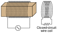
|
|
Also, describe what will happen if the wire coil fails open.
Challenge question: how could we vary the coil's vibrational force without varying the amplitude of the AC power source?
Notes:
Be sure to note in your discussion with students that the coil does not have to be made of a magnetic material, such as iron. Copper or aluminum will work quite nicely because Lenz's Law is an electromagnetic effect, not a magnetic effect.
The real answer to this question is substantially more complex than the one given. In the example given, I assume that the resistance placed in the coil circuit swamps the coil's self-inductance. In a case such as this, the coil current will be (approximately) in-phase with the induced voltage. Since the induced voltage will lag 90 degrees behind the incident (electromagnet) field, this means the coil current will also lag 90 degrees behind the incident field, and the force generated between that coil and the AC electromagnet will alternate between attraction and repulsion:
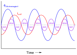
|
|
Note the equal-amplitude attraction and repulsion peaks shown on the graph.
However, in situations where the coil's self-inductance is significant, the coil current will lag behind the induced voltage, causing the coil current waveform to fall further out of phase with the electromagnet current waveform:
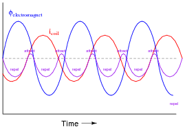
|
|
Given a phase shift between the two currents greater than 90 degrees (approaching 180 degrees), there is greater repulsion force for greater duration than there is attractive force. If the coil were a superconducting ring (no resistance whatsoever), the force would only be repulsive!
So, the answer to this ßimple" Lenz's Law question really depends on the coil circuit: whether it is considered primarily resistive or primarily inductive. Only if the coil's self-inductance is negligible will the reactive force equally alternate between attraction and repulsion. The more inductive (the less resistive) the coil circuit becomes, the more net repulsion there will be.
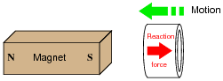
Question 12:
These two electric motor designs are quite similar in appearance, but differ in the specific principle that makes the rotor move:
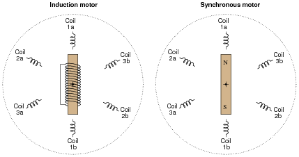
|
|
Synchronous AC motors use a permanent magnet rotor, while induction motors use an electromagnet rotor. Explain what practical difference this makes in each motor's operation, and also explain the meaning of the motors' names. Why is one called ßynchronous" and the other called ïnduction"?
Challenge question: what would happen if an induction motor were mechanically brought up to speed with its rotating magnetic field? Imagine using an engine or some other prime-mover mechanism to force the induction motor's rotor to rotate at synchronous speed, rather than ßlipping" behind synchronous speed as it usually does. What effect(s) would this have?
Notes:
It is very important that students realize Lenz's Law is an induced effect, which only manifests when a changing magnetic field cuts through perpendicular conductors. Ask your students to explain how the word ïnduction" applies to Lenz's Law, and to the induction motor design. Ask them what conditions are necessary for electromagnetic induction to occur, and how those conditions are met in the normal operation of an induction motor.
The challenge question is really a test of whether or not students have grasped the concept. If they truly understand how electromagnetic induction takes place in an induction motor, they will realize that there will be no induction when the rotor rotates in ßync" with the rotating magnetic field, and they will be able to relate this loss of induction to rotor torque.
Question 13:
Synchronous AC motors operate with zero slip, which is what primarily distinguishes them from induction motors. Explain what ßlip" means for an induction motor, and why synchronous motors do not have it.
Notes:
The concept of ßlip" is confusing to many students, so be prepared to help them understand by way of multiple explanations, Socratic questioning, and perhaps live demonstrations.
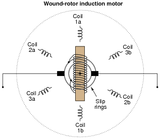
Question 14:
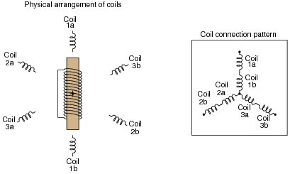
An interesting variation on the induction motor theme is the wound-rotor induction motor. In the simplest form of a wound-rotor motor, the rotor's electromagnet coil terminates on a pair of slip rings which permit contact with stationary carbon brushes, allowing an external circuit to be connected to the rotor coil:
|
|
Explain how this motor can be operated as either a synchronous motor or a "plain" induction motor.
Challenge question: what will happen to this motor if a resistance is connected between the brushes, instead of a DC source or a short-circuit?
Notes:
In reality, almost all large synchronous motors are built this way, with an electromagnetic rotor rather than a permanent-magnet rotor. This allows the motor to start much easier. Ask your students why they think this would be an important feature in a large synchronous motor, to be able to start it as an induction motor. What would happen if AC power were suddenly applied to a large synchronous motor with its rotor already magnetized?
If a resistance is connected between the brushes, it allows for an even easier start-up. By ëasier," I mean a start-up that draws less inrush current, resulting in a gentler ramp up to full speed.
Question 15:
Suppose an induction motor were built to run on single-phase AC power rather than polyphase AC power. Instead of multiple sets of windings, it only has one set of windings:
|
|
Which way would the rotor start to spin as power is applied?
Follow-up question: what does this tell us about the behavior of single-phase induction motors that is fundamentally different from polyphase induction motors?
Challenge question: what does this tell us about the effects of an open line conductor on a three-phase induction motor?
|
|
Notes:
This is a "trick" question, in that the student is asked to determine which direction the rotor will start to spin, when in fact it has no "preferred" direction of rotation. An excellent means of demonstrating this effect is to take a regular single-phase motor and disconnect its start switch so that it is electrically identical to the motor shown in the question, then connect it to an AC power source. It will not spin until you give the shaft a twist with your hand. But be careful: once it starts to turn, it ramps up to full speed quickly!
The real purpose of this question is to get students to recognize the main "handicap" of a single-phase AC motor, and to understand what is required to overcome that limitation. The challenge question essentially asks students what happens to a three-phase motor that is suddenly forced to operate as a single-phase motor due to a line failure. Incidentally, this is called single-phasing of the motor, and it is not good!
Question 16:
Describe the operating principles of these three methods for starting single-phase induction motors:
- �
- Shaded pole
- �
- Split-phase, capacitor
- �
- Split-phase (resistor or inductor)
Notes:
There are many details which can be discussed with students regarding these methods of single-phase motor starting. Thankfully, there are many good-quality sources of information on single-phase motor theory and construction, so finding information on this topic will not be difficult for your students.
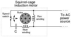
Question 17:
Many single-phase ßquirrel-cage" induction motors use a special start winding which is energized only at low (or no) speed. When the rotor reaches full operating speed, the starting switch opens to de-energize the start winding:
|
|
Explain why this special winding is necessary for the motor to start, and also why there is a capacitor connected in series with this start winding. What would happen if the start switch, capacitor, or start winding were to fail open?
Challenge question: explain what you would have to do to reverse the direction of this "capacitor-start" motor.
Notes:
Capacitor-start squirrel-cage induction motors are very popular in applications where there is a need for high starting torque. Many induction motor shop tools (drill presses, lathes, radial-arm saws, air compressors) use capacitor-start motors.
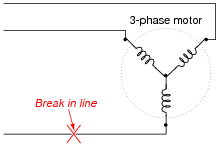
Question 18:
The lines of a three-phase power system may be connected to the terminals of a three-phase motor in several different ways. Which of these altered motor connections will result in the motor reversing direction?
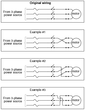
|
|
Notes:
It is helpful to review the concept of phase rotation sequences as a string of letters: A-B-C, or C-B-A. Although these two letter sequences are the most common for denoting the two different rotation directions, they are not the only sequences possible using three letters. For example, A-C-B, B-A-C, C-A-B, and B-C-A are also possibilities. Discuss with your students which of these letter sequences represents the same direction of rotation as A-B-C, and which represent the same direction of rotation as C-B-A. Then, ask your students how they might apply these letter sequences to the different wiring diagrams shown in the question.
Question 19:
Some AC induction motors are equipped with multiple windings so they may operate at two distinct speeds (low speed usually being one-half of high speed). Shown here is the connection diagram for one type of two-speed motor:
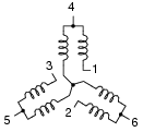
|
|
There are six terminals on the motor itself where the connections are made:
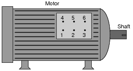
|
|
The motor's datasheet will specify how the connections are to be made. This is typical:
-
Speed f-A f-B f-C Left open Shorted together
Low 1 2 3 4,5,6
High 4 5 6 1,2,3
Explain why the motor runs at half-speed in one connection scheme and full speed in the other. What is going on that makes this possible?
Notes:
Consequent pole motors are not the only design with multiple speeds. Sometimes motors are wound with completely separate, multiple windings, which give them any combinations of speeds desired.
Question 20:
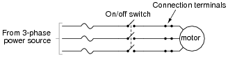
This electric motor was operating just fine, then one day it mysteriously shut down. The electrician discovered two blown fuses, which he then replaced:
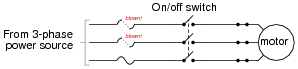
|
|
When the on/off switch was closed again, the motor made a loud "humming" noise, then became quiet after a few seconds. It never turned, though. Upon inspection, the electrician discovered the same two fuses had blown again.
If you were asked to help troubleshoot this electric motor circuit, what would you recommend as the next step?
It would make sense to proceed by answering this question: what type of fault typically blows fuses? What types of tests could you perform on a circuit like this in order to locate those types of faults? Bear in mind that the behavior of electric motors is quite unlike many other types of loads. This is an electromechanical device, so the problem may not necessarily be limited to electrical faults!
Notes:
This question should provoke some interesting discussion! An interesting "twist" to this problem is to suggest (after some discussion) that the motor itself checks out fine when tested with an ohmmeter (no ground faults, no open or shorted windings), and that its shaft may be turned freely by hand. What could possibly be the source of trouble now?