Active filters
Question 1:
| Don't just sit there! Build something!! |
Learning to mathematically analyze circuits requires much study and practice. Typically, students practice by working through lots of sample problems and checking their answers against those provided by the textbook or the instructor. While this is good, there is a much better way.
You will learn much more by actually building and analyzing real circuits, letting your test equipment provide the änswers" instead of a book or another person. For successful circuit-building exercises, follow these steps:
- 1.
- Carefully measure and record all component values prior to circuit construction.
- 2.
- Draw the schematic diagram for the circuit to be analyzed.
- 3.
- Carefully build this circuit on a breadboard or other convenient medium.
- 4.
- Check the accuracy of the circuit's construction, following each wire to each connection point, and verifying these elements one-by-one on the diagram.
- 5.
- Mathematically analyze the circuit, solving for all voltage and current values.
- 6.
- Carefully measure all voltages and currents, to verify the accuracy of your analysis.
- 7.
- If there are any substantial errors (greater than a few percent), carefully check your circuit's construction against the diagram, then carefully re-calculate the values and re-measure.
Avoid using the model 741 op-amp, unless you want to challenge your circuit design skills. There are more versatile op-amp models commonly available for the beginner. I recommend the LM324 for DC and low-frequency AC circuits, and the TL082 for AC projects involving audio or higher frequencies.
As usual, avoid very high and very low resistor values, to avoid measurement errors caused by meter "loading". I recommend resistor values between 1 kW and 100 kW.
One way you can save time and reduce the possibility of error is to begin with a very simple circuit and incrementally add components to increase its complexity after each analysis, rather than building a whole new circuit for each practice problem. Another time-saving technique is to re-use the same components in a variety of different circuit configurations. This way, you won't have to measure any component's value more than once.
Notes:
It has been my experience that students require much practice with circuit analysis to become proficient. To this end, instructors usually provide their students with lots of practice problems to work through, and provide answers for students to check their work against. While this approach makes students proficient in circuit theory, it fails to fully educate them.
Students don't just need mathematical practice. They also need real, hands-on practice building circuits and using test equipment. So, I suggest the following alternative approach: students should build their own "practice problems" with real components, and try to mathematically predict the various voltage and current values. This way, the mathematical theory "comes alive," and students gain practical proficiency they wouldn't gain merely by solving equations.
Another reason for following this method of practice is to teach students scientific method: the process of testing a hypothesis (in this case, mathematical predictions) by performing a real experiment. Students will also develop real troubleshooting skills as they occasionally make circuit construction errors.
Spend a few moments of time with your class to review some of the "rules" for building circuits before they begin. Discuss these issues with your students in the same Socratic manner you would normally discuss the worksheet questions, rather than simply telling them what they should and should not do. I never cease to be amazed at how poorly students grasp instructions when presented in a typical lecture (instructor monologue) format!
A note to those instructors who may complain about the "wasted" time required to have students build real circuits instead of just mathematically analyzing theoretical circuits:
What is the purpose of students taking your course?
If your students will be working with real circuits, then they should learn on real circuits whenever possible. If your goal is to educate theoretical physicists, then stick with abstract analysis, by all means! But most of us plan for our students to do something in the real world with the education we give them. The "wasted" time spent building real circuits will pay huge dividends when it comes time for them to apply their knowledge to practical problems.
Furthermore, having students build their own practice problems teaches them how to perform primary research, thus empowering them to continue their electrical/electronics education autonomously.
In most sciences, realistic experiments are much more difficult and expensive to set up than electrical circuits. Nuclear physics, biology, geology, and chemistry professors would just love to be able to have their students apply advanced mathematics to real experiments posing no safety hazard and costing less than a textbook. They can't, but you can. Exploit the convenience inherent to your science, and get those students of yours practicing their math on lots of real circuits!
Question 2:
In very simple, qualitative terms, rate the impedance of capacitors and inductors as ßeen" by low-frequency and high-frequency signals alike:
- �
- Capacitor as it äppears" to a low frequency signal: (high or low) impedance?
- �
- Capacitor as it äppears" to a high frequency signal: (high or low) impedance?
- �
- Inductor as it äppears" to a low frequency signal: (high or low) impedance?
- �
- Inductor as it äppears" to a high frequency signal: (high or low) impedance?
- �
- Capacitor as it äppears" to a low frequency signal: high impedance.
- �
- Capacitor as it äppears" to a high frequency signal: low impedance.
- �
- Inductor as it äppears" to a low frequency signal: low impedance.
- �
- Inductor as it äppears" to a high frequency signal: high impedance.
Challenge question: what does a capacitor äppear" as to a DC signal?
Notes:
Ask your students how they arrived at their answers for these qualitative assessments. If they found difficulty understanding the relationship of frequency to impedance for reactive components, I suggest you work through the reactance equations qualitatively with them. In other words, evaluate each of the reactance formulae (XL = 2 pf L and XC = [1/(2 pf C)]) in terms of f increasing and decreasing, to understand how each of these components reacts to low- and high-frequency signals.
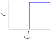
Question 3:
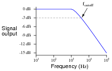
Draw the Bode plot for an ideal high-pass filter circuit:

|
|
Be sure to note the "cutoff frequency" on your plot.
|
|
Follow-up question: a theoretical filter with this kind of idealized response is sometimes referred to as a "brick wall" filter. Explain why this name is appropriate.
Notes:
The plot given in the answer, of course, is for an ideal high-pass filter, where all frequencies below fcutoff are blocked and all frequencies above fcutoff are passed. In reality, filter circuits never attain this ideal ßquare-edge" response. Discuss possible applications of such a filter with your students.
Challenge them to draw the Bode plots for ideal band-pass and band-stop filters as well. Exercises such as this really help to clarify the purpose of filter circuits. Otherwise, there is a tendency to lose perspective of what real filter circuits, with their correspondingly complex Bode plots and mathematical analyses, are supposed to do.
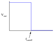
Question 4:
Draw the Bode plot for an ideal low-pass filter circuit:
|
|
Be sure to note the "cutoff frequency" on your plot.
|
|
Follow-up question: a theoretical filter with this kind of idealized response is sometimes referred to as a "brick wall" filter. Explain why this name is appropriate.
Notes:
The plot given in the answer, of course, is for an ideal low-pass filter, where all frequencies below fcutoff are passed and all frequencies above fcutoff are blocked. In reality, filter circuits never attain this ideal ßquare-edge" response. Discuss possible applications of such a filter with your students.
Challenge them to draw the Bode plots for ideal band-pass and band-stop filters as well. Exercises such as this really help to clarify the purpose of filter circuits. Otherwise, there is a tendency to lose perspective of what real filter circuits, with their correspondingly complex Bode plots and mathematical analyses, are supposed to do.
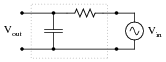
Question 5:
Identify what type of filter this circuit is, and calculate its cutoff frequency given a resistor value of 1 kW and a capacitor value of 0.22 mF:
|
|
Calculate the impedance of both the resistor and the capacitor at this frequency. What do you notice about these two impedance values?
fcutoff = 723.4 Hz
Notes:
Be sure to ask students where they found the cutoff frequency formula for this filter circuit.
When students calculate the impedance of the resistor and the capacitor at the cutoff frequency, they should notice something unique. Ask your students why these values are what they are at the cutoff frequency. Is this just a coincidence, or does this tell us more about how the "cutoff frequency" is defined for an RC circuit?
Question 6:
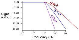
Real filters never exhibit perfect ßquare-edge" Bode plot responses. A typical low-pass filter circuit, for example, might have a frequency response that looks like this:
|
|
What does the term rolloff refer to, in the context of filter circuits and Bode plots? Why would this parameter be important to a technician or engineer?
|
|
Notes:
Point students' attention to the scale used on this particular Bode plot. This is called a log-log scale, where neither vertical nor horizontal axis is linearly marked. This scaling allows a very wide range of conditions to be shown on a relatively small plot, and is very common in filter circuit analysis.
Question 7:
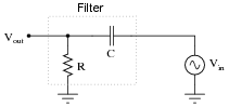
Identify what factor(s) determine the cutoff frequency of this passive filter circuit:
|
|
Give an exact equation predicting this filter circuit's cutoff frequency, and also identify what type of filter it is.
|
Notes:
Nothing fancy here, just a review of passive RC filter circuitry.
Question 8:
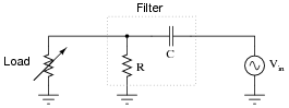
In this passive filter circuit, how will the filter's cutoff frequency be affected by changes in the load resistance? Be as specific as you can in your answer.
|
|
Notes:
Ask your students to define what "cutoff frequency" means. There is more than one definition: one based on output voltage, and one based on output power. When defined in terms of power, the cutoff frequency is sometimes described as f-3 dB.
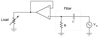
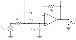
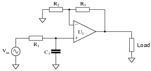
Question 9:
In this active filter circuit, how will the filter's cutoff frequency be affected by changes in the load resistance? Be as specific as you can in your answer.
|
|
Follow-up question: explain the opamp's role in providing immunity to the filter circuit from load resistance changes. How does it accomplish this feat?
Notes:
Ask your students what the function of the opamp is, taken by itself. What do we call an opamp that has its output directly connected to its inverting input? How does this function and name relate to the granting of load-impedance immunity in the filter circuit shown in the question?
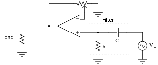
Question 10:
In this filter circuit, how will the filter's cutoff frequency be affected by changes in the potentiometer position? Be as specific as you can in your answer.
|
|
Follow-up question: what does change as the potentiometer wiper is moved back and forth along its adjustment range?
Notes:
Ask your students what the function of the op-amp is (with potentiometer feedback), taken by itself. If there were no filter circuit in place at all, but Vin connected straight to the op-amp's noninverting input, what function would the potentiometer adjustment serve?
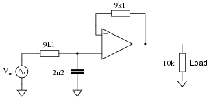
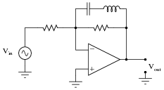
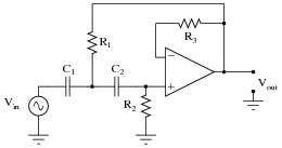
Question 11:
Determine the type (LP, HP, BP, BS) and cutoff frequency of this active filter circuit:
|
|
f-3dB = 7.95 kHz
Follow-up question: explain what the purpose of the 9.1 kW feedback resistor is, since all we're using the opamp for is a voltage buffer anyway (which theoretically does not require resistance in the feedback loop). Furthermore, explain how the Superposition theorem is used to determine the optimum value of this feedback resistance.
Notes:
Ask your students to explain how they arrived at their answers: what formulae did they use, and how did they determine the type of the filter circuit that this is? Ask them if there was any information given in the diagram irrelevant to either determination.
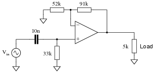
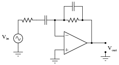
Question 12:
Determine the type (LP, HP, BP, BS) and cutoff frequency of this active filter circuit:
|
|
f-3dB = 482.3 Hz
Follow-up question: the feedback resistor network comprised of the 52 kW and 91 kW resistors not only provides a gain of 1.75 (4.86 dB), but these values were also intentionally chosen to compensate for the effects of DC bias current through the opamp input terminals. You will notice that the parallel combination of 52 kW and 91 kW is approximately equal to 33 kW. Explain why this is significant with reference to the Superposition theorem.
Notes:
Ask your students to explain how they arrived at their answers: what formulae did they use, and how did they determine the type of the filter circuit that this is? Ask them if there was any information given in the diagram irrelevant to either determination.
Question 13:
Compare the voltage gains of these two opamp circuits:
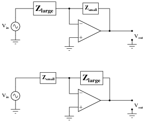
|
|
Which one has the greater AV, and why?
|
|
This opamp circuit has the greater voltage gain, because its [(Zfeedback)/(Zinput)] ratio is greater.
Notes:
It is common to see impedances represented as boxes, if their constituent components are not germane to the operation of the circuit.
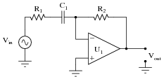
Question 14:
Describe what will happen to the impedance of both the capacitor and the resistor as the input signal frequency increases:
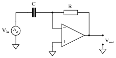
|
|
Also, describe what result the change in impedances will have on the op-amp circuit's voltage gain. If the input signal amplitude remains constant as frequency increases, what will happen to the amplitude of the output voltage? What type of filtering function does this behavior represent?
Follow-up question: normally we calculate the cutoff frequency of a simple RC filter circuit by determining the frequency at which R = XC. Here, things are a little different. Determine the voltage gain (AV) when R = XC, and also determine the phase shift from input to output.
Challenge question #1: explain why the phase shift from input to output for this circuit is always constant, regardless of signal frequency.
Challenge question #2: explain why this type of circuit is usually equipped with a low-value resistor (R1) in series with the input capacitor:
|
|
Notes:
The answer I've given is technically correct, but there is a practical limit here. As we know, the intrinsic gain of an op-amp does not remain constant as signal frequency rises. Ask your students to describe the impact of this phenomenon on the circuit's performance at very high frequencies.
On another note, this same op-amp circuit is known by a particular name when used with DC input signals. Ask your students what this design of circuit is called.
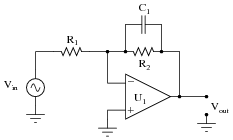
Question 15:
Describe what will happen to the impedance of both the capacitor and the resistor as the input signal frequency increases:
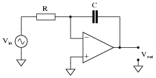
|
|
Also, describe what result the change in impedances will have on the op-amp circuit's voltage gain. If the input signal amplitude remains constant as frequency increases, what will happen to the amplitude of the output voltage? What type of filtering function does this behavior represent?
Challenge question: explain why this type of circuit is usually equipped with a high-value resistor (R2) in parallel with the feedback capacitor:
|
|
Notes:
This same op-amp circuit is known by a particular name when used with DC input signals. Ask your students what this design of circuit is called. When receiving a DC input signal, what function does it serve? The answer to this is key to answering the "challenge" question.
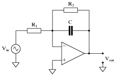
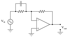
Question 16:
Approximate the voltage gains of this active filter circuit at f = 0 and f = � (assume ideal op-amp behavior):
|
|
Approximate the voltage gains of this other äctive filter" circuit at f = 0 and f = � (assume ideal op-amp behavior):
|
|
What type of filtering function (low pass, high pass, band pass, band stop) is provided by both these filter circuits? Comparing these two circuit designs, which one do you think is more practical? Explain your answer.
|
|
Notes:
Discuss with your students their methods of determining filter type. How did they approach this problem, to see what type of filter both these circuits were?
Also, discuss with your students the problem of having an amplifier circuit with an unchecked gain (approaching infinity). Ask them what is wrong with obtaining such high voltage gains from any amplifier. Have them describe to you the effect of a huge voltage gain on the integrity of the amplified signal.
Question 17:
Approximate the voltage gains of this active filter circuit at f = 0 and f = � (assume ideal op-amp behavior):
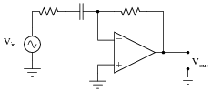
|
|
Approximate the voltage gains of this other äctive filter" circuit at f = 0 and f = � (assume ideal op-amp behavior):
|
|
What type of filtering function (low pass, high pass, band pass, band stop) is provided by both these filter circuits? Comparing these two circuit designs, which one do you think is more practical? Explain your answer.
|
|
Notes:
Discuss with your students their methods of determining filter type. How did they approach this problem, to see what type of filter both these circuits were?
Also, discuss with your students the problem of having an amplifier circuit with an unchecked gain (approaching infinity). Ask them what is wrong with obtaining such high voltage gains from any amplifier. Have them describe to you the effect of a huge voltage gain on the integrity of the amplified signal.
Question 18:
Identify the function of this active filter:
|
|
It is low pass, high pass, band pass, or band stop? Explain your answer.
Notes:
Discuss with your students their methods of determining filter type. How did they approach this problem, to see what type of filter this circuit was? Determining the identify of a "band-" filter is more difficult than with a low- or a high- pass filter circuit, because the behavior is roughly the same at both extremes of the frequency range.
Question 19:
Identify the function of this active filter:
|
|
It is low pass, high pass, band pass, or band stop? Explain your answer.
Challenge question: how much voltage gain does this amplifier have at resonance? How much voltage gain does it have at f = 0 and f = �, if the two resistor values are equal?
Notes:
If some students have difficulty analyzing the function of this circuit, ask them to identify the total impedance of a series-connected inductor and capacitor at resonance, then transfer that amount of impedance to the circuit to see what the effects will be at the resonant frequency.
Question 20:
A very popular active filter topology is called the Sallen-Key. Two examples of Sallen-Key active filter circuits are shown here:
|
|
|
|
Determine which of these Sallen-Key filters is low pass, and which is high pass. Explain your answers.
Challenge question: what is the purpose of resistor R3 in each circuit?
Notes:
The word "topology" may be strange to your students. If any of them ask you what it means, ask them if they own a dictionary!
Like all the other active filter circuits, the fundamental characteristic of each filter may be determined by qualitative analysis at f = 0 and f = �. This is a form of thought experiment: determining the characteristics of a circuit by imagining the effects of certain given conditions, following through by analysis based on "first principles" of circuits, rather than by researching what the circuit's intended function is.
Resistor R3 is actually not essential to the circuit's operation, but is normally found in Sallen-Key filters anyway. If it makes the analysis of the circuit any simpler, tell your students they may replace that resistor with a straight wire in their schematic diagrams.
Question 21:
In active and passive filter design literature, you often come across filter circuits classified as one of three different names:
- �
- Chebyshev
- �
- Butterworth
- �
- Bessel
Describe what each of these names means. What, exactly, distinguishes a "Chebyshev" filter circuit from a "Butterworth" filter circuit?
Notes:
I purposely omitted Bode plot examples for these three filter classifications. Presentation and examination of Bode plots is an appropriate activity for discussion time. Draw a set of Bode plot axes on the whiteboard, and then have students draw approximate Bode plots for each filter response, as determined from their research.
Question 22:
Choose appropriate values for this Sallen-Key high-pass filter circuit to give it a cutoff frequency of 7 kHz with a "Butterworth" response:
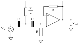
|
|
|
A good guideline to follow is to make sure no component impedance (ZR or ZC) at the cutoff frequency is less than 1 kW or greater than 100 kW.
- �
- C = 3.3 nF
- �
- R = 9.744 kW
- �
- R/2 = 4.872 kW
Follow-up question: how would you suggest we obtain the precise resistance values necessary to build this circuit?
Notes:
In order for students to solve for R, they must algebraically manipulate the cutoff frequency formula. Ask them why we might choose a standard value for capacitance and then calculate a non-standard value for resistance. Why not the other way around (first choose R, then calculate C)?
Question 23:
Choose appropriate values for this Sallen-Key low-pass filter circuit to give it a cutoff frequency of 4.2 kHz with a "Butterworth" response:
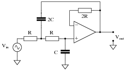
|
|
|
A good guideline to follow is to make sure no component impedance (ZR or ZC) at the cutoff frequency is less than 1 kW or greater than 100 kW.
- �
- C = 0.0047 mF
- �
- 2C = 0.0094 mF
- �
- R = 5.701 kW
- �
- 2R = 11.402 kW
Follow-up question: while 0.0047 mF is a common capacitor size, 0.0094 mF is not. Explain how you could obtain this precise value of capacitance needed to build this circuit.
Notes:
In order for students to solve for R, they must algebraically manipulate the cutoff frequency formula. Ask them why we might choose a standard value for capacitance and then calculate a non-standard value for resistance. Why not the other way around (first choose R, then calculate C)?
Question 24:
A popular passive filtering network called the twin-tee is often coupled with an operational amplifier to produce an active filter circuit. Two examples are shown here:
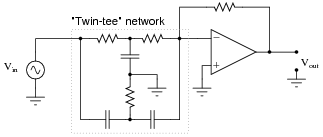
|
|
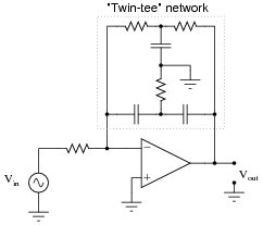
|
|
Identify which of these circuits is band-pass, and which is band-stop. Also, identify the type of response typically provided by the twin-tee network alone, and how that response is exploited to make two different types of active filter responses.
Notes:
Like all the other active filter circuits, the fundamental characteristic of each filter may be determined by qualitative analysis at f = 0 and f = �.
An interesting concept at work here is the inversion of a function by placement inside the feedback loop of a negative-feedback opamp circuit. What is a band-stop filter all by itself forces the opamp to be a band-pass if placed within the negative feedback signal path. Discuss this very important concept with your students, as this is most definitely not the only application for it!
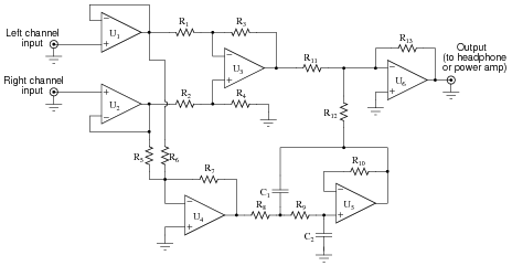
Question 25:
Singers who wish to practice singing to popular music find that the following vocal eliminator circuit is useful:
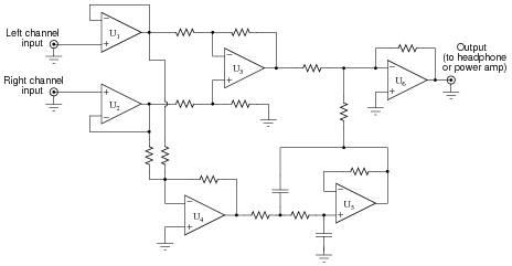
|
|
The circuit works on the principle that vocal tracks are usually recorded through a single microphone at the recording studio, and thus are represented equally on each channel of a stereo sound system. This circuit effectively eliminates the vocal track from the song, leaving only the music to be heard through the headphone or speaker.
Operational amplifiers U1 and U2 provide input buffering so that the other opamp circuits do not excessively load the left and right channel input signals. Opamp U3 performs the subtraction function necessary to eliminate the vocal track.
You might think that these three opamps would be sufficient to make a vocal eliminator circuit, but there is one more necessary feature. Not only is the vocal track common to both left and right channels, but so is most of the bass (low-frequency) tones. Thus, the first three opamps (U1, U2, and U3) eliminate both vocal and bass signals from getting to the output, which is not what we want.
Explain how the other three opamps (U4, U5, and U6) work to restore bass tones to the output so they are not lost along with the vocal track.
Notes:
Not only does this circuit illustrate a neat application of opamps, but it also showcases modular operational circuit design, where each opamp (and its supporting passive components) performs exactly one task.
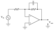
Question 26:
Predict how the operation of this active filter circuit will be affected as a result of the following faults. Consider each fault independently (i.e. one at a time, no multiple faults):
|
|
- �
- Resistor R1 fails open:
- �
- Capacitor C1 fails open:
- �
- Solder bridge (short) across resistor R1:
- �
- Solder bridge (short) across capacitor C1:
- �
- Resistor R2 fails open:
- �
- Resistor R3 fails open:
For each of these conditions, explain why the resulting effects will occur.
- �
- Resistor R1 fails open: Filter circuit stops filtering, passes all frequencies.
- �
- Capacitor C1 fails open: No signal output at all from the circuit.
- �
- Solder bridge (short) across resistor R1: No signal output at all from the circuit.
- �
- Solder bridge (short) across capacitor C1: Filter circuit stops filtering, passes all frequencies.
- �
- Resistor R2 fails open: Voltage gain of circuit decreases to value of 1 (0 dB).
- �
- Resistor R3 fails open: Filter circuit outputs square wave at all frequencies.
Notes:
The purpose of this question is to approach the domain of circuit troubleshooting from a perspective of knowing what the fault is, rather than only knowing what the symptoms are. Although this is not necessarily a realistic perspective, it helps students build the foundational knowledge necessary to diagnose a faulted circuit from empirical data. Questions such as this should be followed (eventually) by other questions asking students to identify likely faults based on measurements.
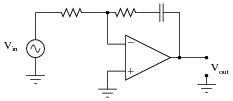
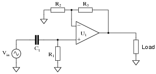
Question 27:
Predict how the operation of this active filter circuit will be affected as a result of the following faults. Consider each fault independently (i.e. one at a time, no multiple faults):
|
|
- �
- Resistor R1 fails open:
- �
- Capacitor C1 fails open:
- �
- Solder bridge (short) across resistor R1:
- �
- Solder bridge (short) across capacitor C1:
- �
- Resistor R2 fails open:
- �
- Resistor R3 fails open:
For each of these conditions, explain why the resulting effects will occur.
- �
- Resistor R1 fails open: No signal output at all from the circuit.
- �
- Capacitor C1 fails open: Filter circuit stops filtering, passes all frequencies.
- �
- Solder bridge (short) across resistor R1: Filter circuit stops filtering, passes all frequencies.
- �
- Solder bridge (short) across capacitor C1: No signal output at all from the circuit.
- �
- Resistor R2 fails open: Voltage gain of circuit decreases to value of 1 (0 dB).
- �
- Resistor R3 fails open: Filter circuit outputs square wave at all frequencies.
Notes:
The purpose of this question is to approach the domain of circuit troubleshooting from a perspective of knowing what the fault is, rather than only knowing what the symptoms are. Although this is not necessarily a realistic perspective, it helps students build the foundational knowledge necessary to diagnose a faulted circuit from empirical data. Questions such as this should be followed (eventually) by other questions asking students to identify likely faults based on measurements.
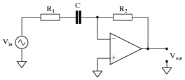
Question 28:
Predict how the operation of this active differentiator circuit will be affected as a result of the following faults. Consider each fault independently (i.e. one at a time, no multiple faults):

|
|
- �
- Resistor R1 fails open:
- �
- Capacitor C1 fails open:
- �
- Solder bridge (short) across resistor R1:
- �
- Solder bridge (short) across capacitor C1:
For each of these conditions, explain why the resulting effects will occur.
- �
- Resistor R1 fails open: Output signal is always a square wave.
- �
- Capacitor C1 fails open: No output signal at all.
- �
- Solder bridge (short) across resistor R1: No output signal at all.
- �
- Solder bridge (short) across capacitor C1: Output signal is always a square wave.
Notes:
The purpose of this question is to approach the domain of circuit troubleshooting from a perspective of knowing what the fault is, rather than only knowing what the symptoms are. Although this is not necessarily a realistic perspective, it helps students build the foundational knowledge necessary to diagnose a faulted circuit from empirical data. Questions such as this should be followed (eventually) by other questions asking students to identify likely faults based on measurements.
Question 29:
Predict how the operation of this active filter circuit will be affected as a result of the following faults. Consider each fault independently (i.e. one at a time, no multiple faults):
|
|
- �
- Resistor R1 fails open:
- �
- Resistor R2 fails open:
- �
- Capacitor C1 fails open:
- �
- Solder bridge (short) across resistor R1:
- �
- Solder bridge (short) across resistor R2:
- �
- Solder bridge (short) across capacitor C1:
For each of these conditions, explain why the resulting effects will occur.
- �
- Resistor R1 fails open: No output signal at all.
- �
- Resistor R2 fails open: Output saturates (either positive or negative) when there is any DC voltage input to the circuit.
- �
- Capacitor C1 fails open: No filtering action at all, merely operates as a fixed-gain amplifier.
- �
- Solder bridge (short) across resistor R1: Output signal is always a square wave.
- �
- Solder bridge (short) across resistor R2: No output signal at all.
- �
- Solder bridge (short) across capacitor C1: No output signal at all.
Notes:
The purpose of this question is to approach the domain of circuit troubleshooting from a perspective of knowing what the fault is, rather than only knowing what the symptoms are. Although this is not necessarily a realistic perspective, it helps students build the foundational knowledge necessary to diagnose a faulted circuit from empirical data. Questions such as this should be followed (eventually) by other questions asking students to identify likely faults based on measurements.
Question 30:
Predict how the operation of this active filter circuit will be affected as a result of the following faults. Consider each fault independently (i.e. one at a time, no multiple faults):
|
|
- �
- Resistor R1 fails open:
- �
- Resistor R2 fails open:
- �
- Capacitor C1 fails open:
- �
- Solder bridge (short) across resistor R1:
- �
- Solder bridge (short) across resistor R2:
- �
- Solder bridge (short) across capacitor C1:
For each of these conditions, explain why the resulting effects will occur.
- �
- Resistor R1 fails open: No output signal at all.
- �
- Resistor R2 fails open: Output signal is always a square wave.
- �
- Capacitor C1 fails open: No output signal at all.
- �
- Solder bridge (short) across resistor R1: Output signal is a square wave at high frequencies (too much high-frequency gain).
- �
- Solder bridge (short) across resistor R2: No output signal at all.
- �
- Solder bridge (short) across capacitor C1: No filtering action at all, merely operates as a fixed-gain amplifier.
Notes:
The purpose of this question is to approach the domain of circuit troubleshooting from a perspective of knowing what the fault is, rather than only knowing what the symptoms are. Although this is not necessarily a realistic perspective, it helps students build the foundational knowledge necessary to diagnose a faulted circuit from empirical data. Questions such as this should be followed (eventually) by other questions asking students to identify likely faults based on measurements.
Question 31:
This vocal eliminator circuit used to work just fine, but then one day it seemed to lose a lot of its bass. It still did its job of eliminating the vocal track, but instead of hearing the full range of musical tones it only reproduced the high frequencies, while the low frequency tones were lost:

|
|
Identify the following fault possibilities:
One resistor failure (either open or shorted) that could cause this to happen:
One capacitor failure (either open or shorted) that could cause this to happen:
One opamp failure that could cause this to happen:
For each of these proposed faults, explain why the bass tones would be lost.
One resistor failure (either open or shorted) that could cause this to happen: R8 failed open.
One capacitor failure (either open or shorted) that could cause this to happen: C2 failed shorted.
One opamp failure that could cause this to happen: U4 failed.
Notes:
Ask your students to explain how they identified their proposed faults, and also how they were able to identify component that must still be working properly.
Question 32:
This vocal eliminator circuit used to work just fine, but then one day it stopped eliminating the vocal track. The tone of the music sounded a bit heavy on the bass, and the vocal track was there when it shouldn't have been there:
|
|
Identify the following fault possibilities:
One resistor failure (either open or shorted) that could cause this to happen:
One opamp failure that could cause this to happen:
For each of these proposed faults, explain why the bass tones would be lost.
One resistor failure (either open or shorted) that could cause this to happen: R2 failed open.
One opamp failure that could cause this to happen: U2 failed.
Notes:
Ask your students to explain how they identified their proposed faults, and also how they were able to identify component that must still be working properly.