Elementary amplifier theory
Question 1:
Fundamentally, an amplifier is a device that takes in a low-power signal and outputs a magnified (power-boosted) facsimile of the input signal. Explain how it is possible for such a device to exist. Doesn't the Law of Energy Conservation (Ënergy can neither be created nor destroyed") preclude the existence of a power-boosting device?
Follow-up question: is a step-up transformer an amplifier? Why or why not?
Notes:
The amplifiers your students will be studying are electronic devices, but other types of amplifiers exist. Discuss with them some examples of common, non-electronic amplifiers.
Question 2:
An important parameter of every amplifier is gain. Explain what "gain" is, and write a simple equation defining gain in terms of signal voltage.
|
|
Notes:
As your students should be able to discern through context, the symbol used to represent gain in equations is the capital letter Ä". One potential point of confusion is the difference between the two gain equations shown in the answer. Why would we have two different equations saying pretty much the same thing? If this issue comes up in discussion, you can give your students the example of an amplifier with a DC bias, where Vout = (4)(Vin) + 3 volts. Here, the (AC) gain is always 4, but the DC gain varies according to how much voltage we apply to the input!
Based on this example, which gain calculation do your students think is the more practical?
Question 3:
At the heart of every amplifier is a device that uses one signal to control another. In electronics, this means a device that uses a small voltage or current signal to control a larger voltage or current.
The first electronic amplifying circuits were constructed with devices called electron tubes instead of transistors. Tubes still find specialized applications in electronics, but they have largely been replaced by transistors. Why is this? What advantages do transistors have over tubes as amplifying devices?
Notes:
Electron tubes used to be the "workhorses" of the electronics world, acting as power control and amplification devices for a wide range of applications. It should be interesting to listen to your students' feedback on this question, being that there is a lot of "tube" information on the internet. IEEE Spectrum magazine had a couple of excellent articles on electron tubes and their applications, which I would strongly encourage any interested students to read.
Question 4:
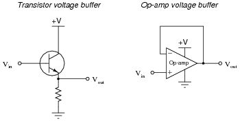
A very common type of amplifier used in electronic circuits is the voltage buffer, sometimes called a voltage follower. There are two simple forms of this circuit, one using a single transistor and the other using an integrated circuit called an operational amplifier:
|
|
The voltage gain of each of these devices is unity (AV = 1). My question to you is this: what possible use is an amplifier that doesn't even amplify the voltage of its input signal? If the output voltage is the same magnitude as the input voltage, then is this circuit really amplifying anything at all? A straight piece of wire outputs the same voltage that it receives in!
Explain the practical purpose for these very popular amplifier circuit configurations.
Notes:
Voltage buffers are almost ubiquitous in modern electronic circuitry, so they cannot be dismissed as useless. Discuss with your students some possible applications of voltage buffers. When would we want to amplify a signal's current without amplifying the voltage? Do your students think there might be any application for this type of circuit in electronic test equipment (voltmeters, especially?).
Question 5:
An important operational parameter of an amplifier is its bandwidth. Describe what "bandwidth" means in the general sense, and give an example of an amplifier application where bandwidth is important.
Notes:
As your students research the word "bandwidth," they will find this term has application in many areas other than amplifiers. Discuss this term, both in the context of amplifiers and in the context of other applications.
Question 6:
Most of the simple amplifiers you will be initially studying tend to lose gain as the frequency of the amplified signal increases. This loss of gain is sometimes quantified in terms of rolloff, usually expressed in units of decibels per octave (dB/octave).
What, exactly, is "rolloff?" What is an öctave," in the context of the units of measurement used to specify rolloff? If we were to plot the response of a typical amplifier in the form of a Bode plot, what type of filter circuit characteristic (band-pass, band-stop, etc.) would it best resemble?
An öctave" denotes a doubling of signal frequency. This unit applies well to logarithmic-scale Bode plots.
Notes:
Have one of your students draw a picture of a Bode plot for a (realistic) low-pass filter: that is, a non-ideal low-pass filter response. Review with your students what a log-scale plot looks like, and ask them to relate the ratio-units of "decibel" and öctave" to such a scale.
Question 7:
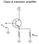
A Class-A transistor amplifier uses a single transistor to generate an output signal to a load. The amplifier shown here happens to be of the "common collector" topology, one of three configurations common to single-transistor circuits:
|
|
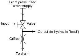
An analogue for this electronic circuit is this water-pressure control, consisting of a variable valve passing water through an orifice (a restriction), then on to a drain:
|
|
The ïnput" to this amplifier is the positioning of the valve control handle. The öutput" of this amplifier is water pressure measured at the end of the horizontal öutput" pipe.
Explain how either of these "circuits" meets the criteria of being an amplifier. In other words, explain how power is boosted from input to output in both these systems. Also, describe how efficient each of these amplifiers is, ëfficiency" being a measure of how much current (or water) goes to the load device, as compared to how much just goes straight through the controlling element and back to ground (the drain).
Notes:
Wasteful they may be, but "Class-A" transistor circuits find very common use in modern electronics. Explain to your students that its inefficiency restricts its practical use to low-power applications.
Question 8:
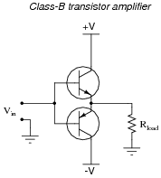
A class-B transistor amplifier (sometimes called a push-pull amplifier) uses a pair of transistors to generate an output signal to a load. The circuit shown here has been simplified for the sake of illustrating the basic concept:
|
|
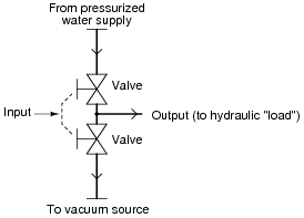
An analogue for this electronic circuit is this water-pressure control, consisting of two variable valves. One valve connects the output pipe to a supply of pressurized water, and the other connects the output pipe to a source of vacuum (suction):
|
|
The ïnput" to this amplifier is the positioning of the valve control handle. The öutput" of this amplifier is water pressure measured at the end of the horizontal öutput" pipe. Valve action is synchronized such that only one valve is open at any given time, just as no more than one transistor will be ön" at any given time in the class-B electronic circuit.
Explain how either of these "circuits" meets the criteria of being an amplifier. In other words, explain how power is boosted from input to output in both these systems. Also, describe how efficient each of these amplifiers is, ëfficiency" being a measure of how much current (or water) goes to the load device, as compared to how much just goes straight from one supply "rail" to the other (from pressure to vacuum).
Notes:
Push-pull amplifiers are a bit more difficult to understand than simple class-A (single-ended), so be sure to take whatever time is necessary to discuss this concept with your students. Ask them to trace current through the load resistor for different input voltage conditions. Your students need not know any details of transistor operation, except that a positive input voltage turns on the upper transistor, and a negative input voltage turns on the lower transistor.
Question 9:
An amplifier has a voltage gain of 5 and a current gain of 75, both figures being ratios. Calculate the following gains:
- �
- Power gain (as a ratio)
- �
- Power gain (dB)
- �
- Voltage gain (dB)
- �
- Current gain (dB)
- �
- Power gain (as a ratio) = 375
- �
- Power gain (dB) = 25.74 dB
- �
- Voltage gain (dB) = 13.98 dB
- �
- Current gain (dB) = 37.50 dB
Notes:
Some of your students will probably get the power calculations correct, but be off by a factor of two on the voltage and current gain (dB) calculations. Remind them that a different equation is used to calculate voltage and current gain in dB than is used in power calculations.
Question 10:
What is the overall voltage gain of two cascaded amplifiers (the output of the first amplifier going into the input of the second), each with an individual voltage gain of 3 dB? Express the overall voltage gain in decibels, and also as a ratio.
Notes:
Ask your students to convert the figure of 3 dB (voltage gain) into a ratio. How does this ratio compare with the overall ratio for the two cascaded amplifiers? What do the figures indicate about cascaded gains in general, expressed in decibel form as well as ratio form? Ask your students if they think it is mathematically easier to compute cascaded gains in ratio form or decibel, and why.