Class C BJT amplifiers
Question 1:
A common class of operation used in radio-frequency (RF) amplifier circuits is class-C. Explain what this means, contrasting it against the class-A and class-B operations common in audio-frequency amplifier circuits.
Notes:
A natural question that arises when students first hear of class-C operation is, "How does a class-C amplifier circuit reproduce the entire waveform, if the transistor is completely off most of the time?" The answer to this lies in resonance, usually supplied in the form of a tank circuit, to maintain oscillations while the transistor is cut off.
Question 2:
Contrast class-A, class-B, and class-C amplifier operations, explaining what defines each class. Then, rank these three classes in order of least power efficiency to greatest power efficiency.
Class-A is least efficient, followed by class-B, and then class-C which is most power efficient.
Notes:
Students are liable to wonder why class-C operation is not the most popular in electronic circuits, since it is the most power-efficient of the three classes. Discuss the limitations of class-C operation, specifically in terms of waveform distortion.
Question 3:
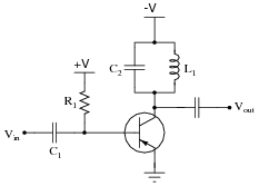
Shown here is a schematic diagram for a class-C RF (radio frequency) amplifier circuit:
|
|
This circuit will look very strange if you are accustomed to analyzing audio-frequency and DC amplifier circuits. Note some of the distinct differences between this amplifier and an amplifier used to boost audio signals. Also, explain what "class-C" operation means, and how this amplifier is able to output a continuous sine wave despite the transistor's behavior in class-C mode.
Finally, write an equation that predicts this amplifier's operating frequency, based on certain component values which you identify.
|
Follow-up question: why is this mode of amplifier operation - where the transistor is off most of the time and a tank circuit sustains sinusoidal oscillations - desirable for an amplifier circuit? Could this technique be applied to audio-frequency amplifier circuits? Why or why not?
Notes:
Perhaps the most noteworthy detail of this circuit is the positive biasing voltage, despite the transistor being PNP and VCC being negative. Ask your students to explain why this is necessary to get the transistor operating in class-C mode.