Boolean algebra
Question 1:
|
Don't just sit there! Build something!! |
Learning to analyze digital circuits requires much study and practice. Typically, students practice by working through lots of sample problems and checking their answers against those provided by the textbook or the instructor. While this is good, there is a much better way.
You will learn much more by actually
building and analyzing real circuits, letting your test equipment provide the änswers" instead of a book or another person. For successful circuit-building exercises, follow these steps:
-
1.
-
Draw the schematic diagram for the digital circuit to be analyzed.
-
2.
- Carefully build this circuit on a breadboard or other convenient medium.
-
3.
- Check the accuracy of the circuit's construction, following each wire to each connection point, and verifying these elements one-by-one on the diagram.
-
4.
- Analyze the circuit, determining all output logic states for given input conditions.
-
5.
- Carefully measure those logic states, to verify the accuracy of your analysis.
-
6.
- If there are any errors, carefully check your circuit's construction against the diagram, then carefully re-analyze the circuit and re-measure.
Always be sure that the power supply voltage levels are within specification for the logic circuits you plan to use. If TTL, the power supply
must be a 5-volt regulated supply, adjusted to a value as close to 5.0 volts DC as possible.
One way you can save time and reduce the possibility of error is to begin with a very simple circuit and incrementally add components to increase its complexity after each analysis, rather than building a whole new circuit for each practice problem. Another time-saving technique is to re-use the same components in a variety of different circuit configurations. This way, you won't have to measure any component's value more than once.
Reveal Answer
Let the electrons themselves give you the answers to your own "practice problems"!
Notes:
It has been my experience that students require much practice with circuit analysis to become proficient. To this end, instructors usually provide their students with lots of practice problems to work through, and provide answers for students to check their work against. While this approach makes students proficient in circuit theory, it fails to fully educate them.
Students don't just need mathematical practice. They also need real, hands-on practice building circuits and using test equipment. So, I suggest the following alternative approach: students should build their own "practice problems" with real components, and try to predict the various logic states. This way, the digital theory "comes alive," and students gain practical proficiency they wouldn't gain merely by solving Boolean equations or simplifying Karnaugh maps.
Another reason for following this method of practice is to teach students scientific method: the process of testing a hypothesis (in this case, logic state predictions) by performing a real experiment. Students will also develop real troubleshooting skills as they occasionally make circuit construction errors.
Spend a few moments of time with your class to review some of the "rules" for building circuits before they begin. Discuss these issues with your students in the same Socratic manner you would normally discuss the worksheet questions, rather than simply telling them what they should and should not do. I never cease to be amazed at how poorly students grasp instructions when presented in a typical lecture (instructor monologue) format!
I highly recommend CMOS logic circuitry for at-home experiments, where students may not have access to a 5-volt regulated power supply. Modern CMOS circuitry is far more rugged with regard to static discharge than the first CMOS circuits, so fears of students harming these devices by not having a "proper" laboratory set up at home are largely unfounded.
A note to those instructors who may complain about the "wasted" time required to have students build real circuits instead of just mathematically analyzing theoretical circuits:
What is the purpose of students taking your course?
If your students will be working with real circuits, then they should learn on real circuits whenever possible. If your goal is to educate theoretical physicists, then stick with abstract analysis, by all means! But most of us plan for our students to do something in the real world with the education we give them. The "wasted" time spent building real circuits will pay huge dividends when it comes time for them to apply their knowledge to practical problems.
Furthermore, having students build their own practice problems teaches them how to perform primary research, thus empowering them to continue their electrical/electronics education autonomously.
In most sciences, realistic experiments are much more difficult and expensive to set up than electrical circuits. Nuclear physics, biology, geology, and chemistry professors would just love to be able to have their students apply advanced mathematics to real experiments posing no safety hazard and costing less than a textbook. They can't, but you can. Exploit the convenience inherent to your science, and get those students of yours practicing their math on lots of real circuits!
Hide Answer
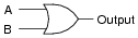
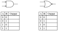
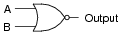
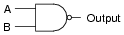
Question 2:
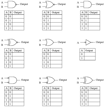
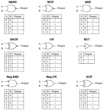
Identify each of these logic gates by name, and complete their respective truth tables:
Reveal Answer
Notes:
In order to familiarize students with the standard logic gate types, I like to given them practice with identification and truth tables each day. Students need to be able to recognize these logic gate types at a glance, or else they will have difficulty analyzing circuits that use them.
Hide Answer
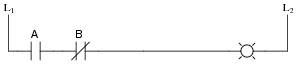
Question 3:
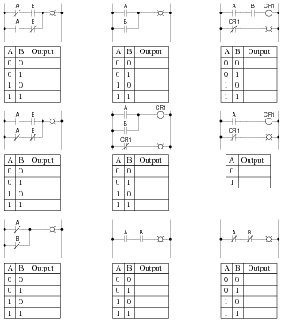
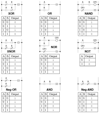
Identify each of these relay logic functions by name (AND, OR, NOR, etc.) and complete their respective truth tables:
Reveal Answer
Notes:
In order to familiarize students with standard switch contact configurations, I like to given them practice with identification and truth tables each day. Students need to be able to recognize these ladder logic sub-circuits at a glance, or else they will have difficulty analyzing more complex relay circuits that use them.
Hide Answer
Question 4:
The following set of mathematical expressions is the
complete set of "times tables" for the Boolean number system:
Now, nothing seems unusual at first about this table of expressions, since they appear to be the same as multiplication understood in our normal, everyday system of numbers. However, what is unusual is that these four statements comprise the entire set of rules for Boolean multiplication!
Explain how this can be so, being that there is no statement saying 1 ×2 = 2 or 2 ×3 = 6. Where are all the other numbers besides 0 and 1?
Reveal Answer
Boolean quantities can only have one out of two possible values: either 0 or 1. There is no such thing as "2" - or any other digit besides 0 or 1 for that matter - in the set of Boolean numbers!
Notes:
Some students with background in computers may ask if Boolean is the same as binary. The answer to this very good question is "no." Binary is simply a numeration system for expressing real numbers, while Boolean is a completely different number system (like integer numbers are to irrational numbers, for example). It is possible to count arbitrarily high in binary, but you can only count as high as "1" in Boolean.
Hide Answer
Question 5:
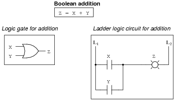
Boolean algebra is a strange sort of math. For example, the complete set of rules for Boolean addition is as follows:
Suppose a student saw this for the very first time, and was quite puzzled by it. What would you say to him or her as an explanation for this? How in the world can 1 + 1 = 1 and not 2? And why are there no more rules for Boolean addition? Where is the rule for 1 + 2 or 2 + 2?
Reveal Answer
Boolean quantities can only have one out of two possible values: either 0 or 1. There is no such thing as "2" in the set of Boolean numbers.
Notes:
Boolean algebra is a strange math, indeed. However, once students understand the limited scope of Boolean quantities, the rationale for Boolean rules of arithmetic make sense. 1 + 1 must equal 1, because there is no such thing as "2" in the Boolean world, and the answer certainly can't be 0.
Hide Answer
Question 6:
Surveying the rules for Boolean addition, the 0 and 1 values seem to resemble the truth table of a very common logic gate. Which type of gate is this, and what does this suggest about the relationship between Boolean addition and logic circuits?
|
Rules for Boolean addition: |
|
Reveal Answer
This set of Boolean expressions resembles the truth table for an OR logic gate circuit, suggesting that Boolean addition may symbolize the logical OR function.
Notes:
Students need to be able to readily associate fundamental Boolean operations with logic circuits. If they can see the relationship between the ßtrange" rules of Boolean arithmetic and something they are already familiar with (i.e. truth tables), the association is made much easier.
Hide Answer
Question 7:
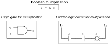
Surveying the rules for Boolean multiplication, the 0 and 1 values seem to resemble the truth table of a very common logic gate. Which type of gate is this, and what does this suggest about the relationship between Boolean multiplication and logic circuits?
|
Rules for Boolean multiplication: |
|
Reveal Answer
This set of Boolean expressions resembles the truth table for an AND logic gate circuit, suggesting that Boolean multiplication may symbolize the logical AND function.
Notes:
Students need to be able to readily associate fundamental Boolean operations with logic circuits. If they can see the relationship between the ßtrange" rules of Boolean arithmetic and something they are already familiar with (i.e. truth tables), the association is made much easier.
Hide Answer
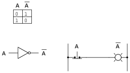
Question 8:
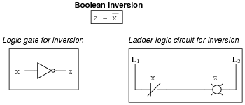
What is the
complement of a Boolean number? How do we represent the complement of a Boolean variable, and what logic circuit function performs the complementation function?
Reveal Answer
A Boolean "complement" is the
opposite value of a given number. This is represented either by overbars or prime marks next to the variable (i.e. the complement of A may be written as either [
`A] or A
�):
Notes:
Students need to be able to readily associate fundamental Boolean operations with logic circuits. If they can see the relationship between the ßtrange" rules of Boolean arithmetic and something they are already familiar with (i.e. truth tables), the association is made much easier.
Hide Answer
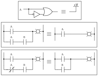
Question 9:
There are three fundamental operations in Boolean algebra: addition, multiplication, and inversion. Each of these operations has an equivalent logic gate function and an equivalent relay circuit configuration. Draw the corresponding gate and ladder logic diagrams for each:
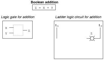
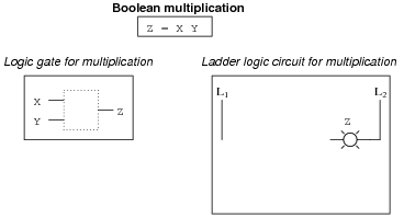
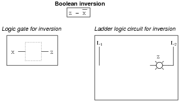
Reveal Answer
Notes:
These three equivalencies will be vital for students to master as they study combinational logic circuits and complex relay logic circuits!
Hide Answer
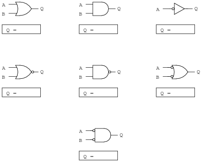
Question 10:
Write the Boolean expression for each of these logic gates, showing how the output (Q) algebraically relates to the inputs (A and B):
Reveal Answer
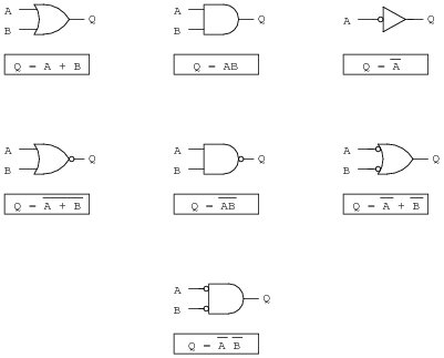
Notes:
In order to familiarize students with Boolean algebra and how it relates to logic gate circuitry, I like to give them daily practice with questions such as this. Students need to be able to recognize these logic gate types at a glance, and also be able to associate the proper Boolean expression with each one, or else they will have difficulty analyzing logic circuits later on.
Hide Answer
Question 11:
Write the Boolean expression for each of these relay logic circuits, showing how the output (Q) algebraically relates to the inputs (A and B):
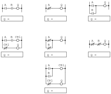
Reveal Answer
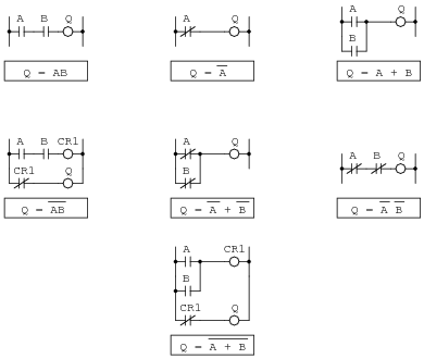
Notes:
In order to familiarize students with Boolean algebra and how it relates to relay logic circuitry, I like to give them daily practice with questions such as this. Students need to be able to figure out how each one of these ladder logic circuits works, and also be able to associate the proper Boolean expression with each one, or else they will have difficulty analyzing more complex relay circuits later on.
Hide Answer
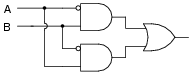
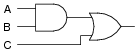
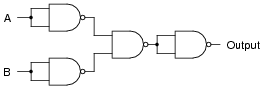
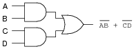
Question 12:
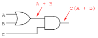
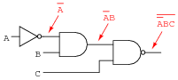
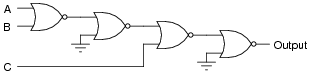
Convert the following logic gate circuit into a Boolean expression, writing Boolean sub-expressions next to each gate output in the diagram:
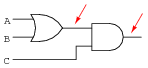
Reveal Answer
Notes:
The process of converting gate circuits into Boolean expressions is really quite simple, if you proceed gate by gate. Have your students share whatever methods or "tricks" they use to write the expressions with the rest of the class.
Hide Answer
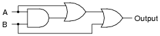
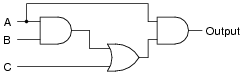
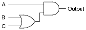
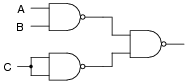
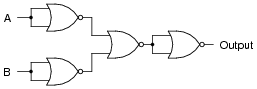
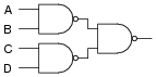
Question 13:
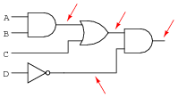
Convert the following logic gate circuit into a Boolean expression, writing Boolean sub-expressions next to each gate output in the diagram:
Reveal Answer
Notes:
The process of converting gate circuits into Boolean expressions is really quite simple, if you proceed gate by gate. Have your students share whatever methods or "tricks" they use to write the expressions with the rest of the class.
Hide Answer
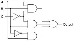
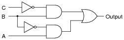
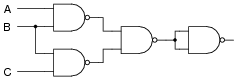
Question 14:
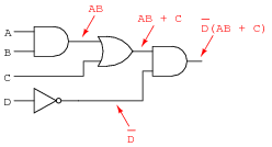
Convert the following logic gate circuit into a Boolean expression, writing Boolean sub-expressions next to each gate output in the diagram:
Reveal Answer
Notes:
The process of converting gate circuits into Boolean expressions is really quite simple, if you proceed gate by gate. Have your students share whatever methods or "tricks" they use to write the expressions with the rest of the class.
Hide Answer
Question 15:
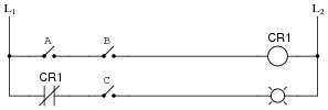
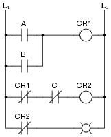
Convert the following relay logic circuit into a Boolean expression, writing Boolean sub-expressions next to each relay coil and lamp in the diagram:
Reveal Answer
Notes:
The process of converting relay logic circuits into Boolean expressions is not quite as simple as it is converting gate circuits into Boolean expressions, but it is manageable. Have your students share whatever methods or "tricks" they use to write the expressions with the rest of the class.
Hide Answer
Question 16:
Convert the following relay logic circuit into a Boolean expression, writing Boolean sub-expressions next to each relay coil and lamp in the diagram:
Reveal Answer
Notes:
The process of converting relay logic circuits into Boolean expressions is not quite as simple as it is converting gate circuits into Boolean expressions, but it is manageable. Have your students share whatever methods or "tricks" they use to write the expressions with the rest of the class.
Hide Answer
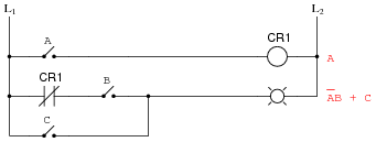
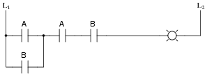
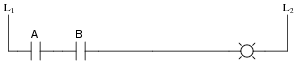
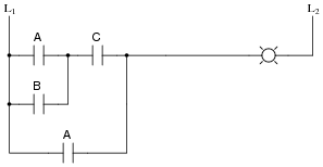
Question 17:
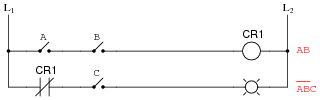
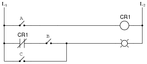
Convert the following relay logic circuit into a Boolean expression, writing Boolean sub-expressions next to each relay coil and lamp in the diagram:
Reveal Answer
Notes:
The process of converting relay logic circuits into Boolean expressions is not quite as simple as it is converting gate circuits into Boolean expressions, but it is manageable. Have your students share whatever methods or "tricks" they use to write the expressions with the rest of the class.
Hide Answer
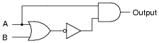
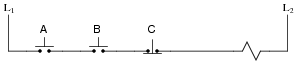
Question 18:
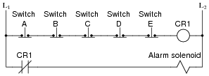
An automotive engineer wants to design a logic circuit that prohibits the engine in a car from being started unless the driver is pressing the clutch pedal while turning the ignition switch to the ßtart" position. The purpose of this feature will be to prevent the car from moving forward while being started if ever the transmission is accidently left in gear.
Suppose we designate the status of the ignition switch ßtart" position with the Boolean variable S (1 = start; 0 = run or off), and the clutch pedal position with the Boolean variable C (1 = clutch pedal depressed; 0 = clutch pedal in normal, unpressed position). Write a Boolean expression for the starter solenoid status, given the start switch (S) and clutch (C) statuses. Then, draw a logic gate circuit to implement this Boolean function.
Reveal Answer
Boolean expression:
Logic gate circuit:

Notes:
This is not a very complicated function to express or implement, the point of this question being mostly to introduce students to a practical use of logic gates and Boolean algebra.
Hide Answer
Question 19:
An engineer hands you a piece of paper with the following Boolean expression on it, and tells you to build a gate circuit to perform that function:
Draw a logic gate circuit for this function.
Reveal Answer
Notes:
The process of converting Boolean expressions into logic gate circuits is not quite as simple as converting gate circuits into Boolean expressions, but it is manageable. Have your students share whatever methods or "tricks" they use to write the expressions with the rest of the class.
Hide Answer
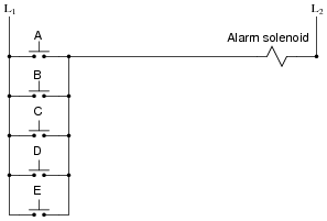
Question 20:
A critical electronic system receives DC power from three power supplies, each one feeding through a diode, so that if one power supply develops an internal short-circuit, it will not cause the others to overload:
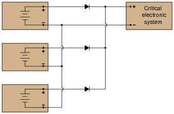
The only problem with this system is that we have no indication of trouble if just one or two power supplies do fail. Since the diode system routes power from any available supply(ies) to the critical system, the system sees no interruption in power if one or even two of the power supplies stop outputting voltage. It would be nice if we had some sort of alarm system installed to alert the technicians of a problem with any of the power supplies, long before the critical system was in jeopardy of losing power completely.
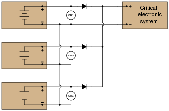
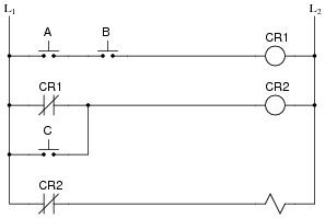
An engineer decides that a relay could be installed at the output of each power supply, prior to the diodes. Contacts from these relays could then be connected to some sort of alarm device (flashing light, bell, etc.) to alert maintenance personnel of any problem:
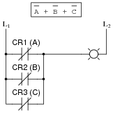
 Part 1:
 Draw a ladder diagram of the relay contacts powering a warning lamp, in such a way that the lamp energizes if
any one or more of the power supplies loses output voltage. Write the corresponding Boolean expression for this circuit, using the letters A, B, and C to represent the status of relay coils CR1, CR2, and CR3, respectively.
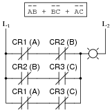
Part 2: The solution to Part 1 worked, but unfortunately it generated "nuisance alarms" whenever a technician powered any one of the supplies down for routine maintenance. The engineer decides that a two-out-of-three-failed alarm system will be sufficient to warn of trouble, while allowing for routine maintenance without creating unnecessary alarms. Draw a ladder diagram of the relay contacts powering a warning lamp, such that the lamp energizes if
any two or more power supplies lose output voltage. The Boolean expression for this is [
`A] [
`B] +[
`B] [
`C] +[
`A] [
`C].
Part 3: Management at this facility changed their minds regarding the safety of a two-out-of-three-failed alarm system. They want the alarm to energize if
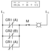
any one of the power supplies fails. However, they also realize that nuisance alarms generated during routine maintenance are unacceptable as well. Asking the maintenance crew to come up with a solution, one of the technicians suggests inserting a "maintenance" switch that will disable the alarm during periods of maintenance, allowing for any of the power supplies to be powered down without creating a nuisance alarm. Modify the alarm circuit of part 1's solution to include such a switch, and correspondingly modify the Boolean expression for the new circuit (call the maintenance switch M).
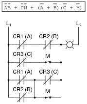
Part 4: During one maintenance cycle, a technician accidently left the alarm bypass switch (M) actuated after he was done. The system operated with the power failure alarm disabled for weeks. When management discovered this, they were furious. Their next suggestion was to have the bypass switch change the conditions for alarm, such that actuating this "M" switch would turn the system from a one-out-of-three-failed alarm into a two-out-of-three-failed alarm. This way, any one power supply may be taken out of service for routine maintenance, yet the alarm will not be completely de-activated. The system will still alarm if two power supplies were to fail. The simplified Boolean expression for this rather complex function is [
`A] [
`B] +[
`C] [
`M] + ([
`A] +[
`B])([
`C] +[
`M]). Draw a ladder diagram for the alarm circuit based on this expression.
Reveal Answer
Part 1 solution:
 Part 2 solution:
 Part 3 solution:
 Part 4 solution:
Follow-up question: how many contacts on each relay (and on the maintenance switch "M") are necessary to implement any of these alarm functions?
Challenge question: can you see any way we could reduce the number of relay contacts necessary in the circuit of solutions 2, yet still achieve the same logic functionality (albeit with a different Boolean expression)?
Notes:
To be honest, I had fun writing the scenarios for different parts of this problem. The evolution of this alarm system is typical for an organization. Someone comes up with an idea, but it doesn't meet all the needs of someone else, so they input their own suggestions, and so on, and so on. Presenting scenarios such as this not only prepare students for the politics of real work, but also underscore the need to "what if?" thinking: to test the proposed solution before implementing it, so that unnecessary problems are avoided.
Hide Answer
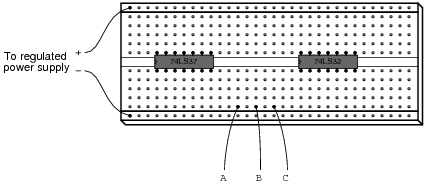
Question 21:
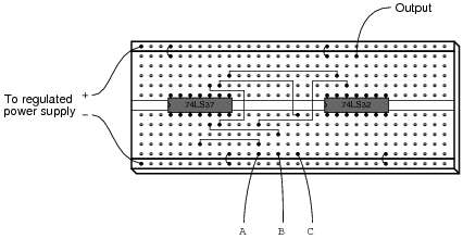
Implement the following Boolean expression in the form of a digital logic circuit:
Form the circuit by making the necessary connections between pins of these integrated circuits on a solderless breadboard:
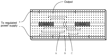
Reveal Answer
The circuit shown is not the only possible solution to this problem:
Notes:
First things first: did students remember to include the power supply connections to each IC? This is a very common mistake!
In order to successfully develop a solution to this problem, of course, students must research the "pinouts" of each integrated circuit. If most students simply present the answer shown to them in the worksheet, challenge them during discussion to present alternative solutions.
Also, ask them this question: ßhould we connect the unused inputs to either ground or VCC, or is it permissible to leave the inputs floating?" Students should not just give an answer to this question, but be able to support their answer(s) with reasoning based on the construction of this type of logic circuit.
Hide Answer
Question 22:
Complete the truth tables for these two Boolean expressions:
-
|
|
A
|
B
|
Output
|
|
|
0
|
0
|
|
|
|
0
|
1
|
|
|
|
1
|
0
|
|
|
|
1
|
1
|
|
|
|
-
|
|
A
|
B
|
Output
|
|
|
0
|
0
|
|
|
|
0
|
1
|
|
|
|
1
|
0
|
|
|
|
1
|
1
|
|
|
|
Reveal Answer
-
|
|
A
|
B
|
Output
|
|
|
0
|
0
|
1
|
|
|
0
|
1
|
1
|
|
|
1
|
0
|
0
|
|
|
1
|
1
|
1
|
|
|
-
|
|
A
|
B
|
Output
|
|
|
0
|
0
|
0
|
|
|
0
|
1
|
1
|
|
|
1
|
0
|
1
|
|
|
1
|
1
|
1
|
|
|
Notes:
Ask your students to explain exactly how they figured out the Öutput" states to fill in the blanks in the truth tables, for the different input combinations. Ask them also to compare and contrast this process with that of figuring out the truth table for a given logic gate circuit.
Hide Answer
Question 23:
Complete the truth tables for these two Boolean expressions:
-
|
|
A
|
B
|
C
|
Output
|
|
|
0
|
0
|
0
|
|
|
|
0
|
0
|
1
|
|
|
|
0
|
1
|
0
|
|
|
|
0
|
1
|
1
|
|
|
|
1
|
0
|
0
|
|
|
|
1
|
0
|
1
|
|
|
|
1
|
1
|
0
|
|
|
|
1
|
1
|
1
|
|
|
|
-
|
|
A
|
B
|
C
|
Output
|
|
|
0
|
0
|
0
|
|
|
|
0
|
0
|
1
|
|
|
|
0
|
1
|
0
|
|
|
|
0
|
1
|
1
|
|
|
|
1
|
0
|
0
|
|
|
|
1
|
0
|
1
|
|
|
|
1
|
1
|
0
|
|
|
|
1
|
1
|
1
|
|
|
|
Reveal Answer
-
|
|
A
|
B
|
C
|
Output
|
|
|
0
|
0
|
0
|
1
|
|
|
0
|
0
|
1
|
1
|
|
|
0
|
1
|
0
|
1
|
|
|
0
|
1
|
1
|
1
|
|
|
1
|
0
|
0
|
1
|
|
|
1
|
0
|
1
|
1
|
|
|
1
|
1
|
0
|
0
|
|
|
1
|
1
|
1
|
1
|
|
|
-
|
|
A
|
B
|
C
|
Output
|
|
|
0
|
0
|
0
|
0
|
|
|
0
|
0
|
1
|
0
|
|
|
0
|
1
|
0
|
0
|
|
|
0
|
1
|
1
|
0
|
|
|
1
|
0
|
0
|
0
|
|
|
1
|
0
|
1
|
1
|
|
|
1
|
1
|
0
|
1
|
|
|
1
|
1
|
1
|
1
|
|
|
Notes:
Ask your students to explain exactly how they figured out the Öutput" states to fill in the blanks in the truth tables, for the different input combinations. Ask them also to compare and contrast this process with that of figuring out the truth table for a given logic gate circuit.
It is especially educational if you ask your students to suggest techniques for quickly determining truth table states, based on certain features of the Boolean expression. For instance, there is a way we can tell the first four Öutput" states in the truth table (reading top to bottom) will be 0 without having to plug values into the expression for B and C. Discuss with your students how we can look at the expression, seeing A as a multiplier for the sum within the parentheses, and immediately conclude that half of the truth table outputs will be 0.
Hide Answer
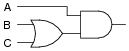
Question 24:
Like real-number algebra, Boolean algebra is subject to the laws of
commutation,
association, and
distribution. These laws allow us to build different logic circuits that perform the same logic function.
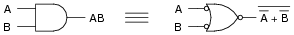
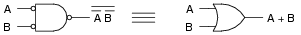
For each of the equivalent circuit pairs shown, write the corresponding Boolean law next to it:
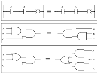
Note: the three short, parallel lines represent ëquivalent to" in mathematics.
Reveal Answer
In order, from top to bottom:
Notes:
The commutative, associative, and distributive laws of Boolean algebra are identical to the respective laws in real number algebra. These should not be difficult concepts for your students to understand. The real benefit of working through these examples is to associate gate and relay logic circuits with Boolean expressions, and to see that Boolean algebra is nothing more than a symbolic means of representing electrical discrete-state (on/off) circuits. In relating otherwise abstract mathematical concepts to something tangible, students build a much better comprehension of the concepts.
Hide Answer
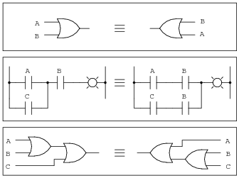
Question 25:
Like real-number algebra, Boolean algebra is subject to certain rules which may be applied in the task of simplifying (reducing) expressions. By being able to algebraically reduce Boolean expressions, it allows us to build equivalent logic circuits using fewer components.
For each of the equivalent circuit pairs shown, write the corresponding Boolean rule next to it:
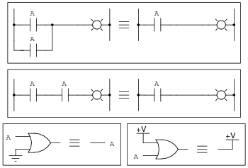
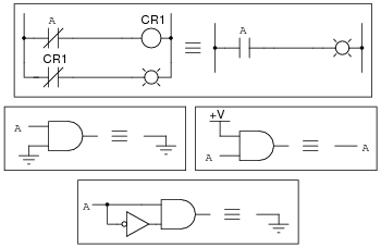
Note: the three short, parallel lines represent ëquivalent to" in mathematics.
Reveal Answer
In order, from top to bottom, left to right:
Notes:
Most of these Boolean rules are identical to their respective laws in real number algebra. These should not be difficult concepts for your students to understand. Some of them, however, are unique to Boolean algebra, having no analogue in real-number algebra. These unique rules cause students the most trouble!
An important benefit of working through these examples is to associate gate and relay logic circuits with Boolean expressions, and to see that Boolean algebra is nothing more than a symbolic means of representing electrical discrete-state (on/off) circuits. In relating otherwise abstract mathematical concepts to something tangible, students build a much better comprehension of the concepts.
Hide Answer
Question 26:
Shown here are six rules of Boolean algebra (these are not the only rules, of course).
-
�
-
A +[`A] = 1
-
�
- A + A = A
-
�
- A + 1 = 1
-
�
- AA = A
-
�
- A + AB = A
-
�
- A +[`A]B = A + B
Determine which rule (or rules) are being used in the following Boolean reductions:
Reveal Answer
|
|
DF
|
+
|
DF
|
C =
|
DF
|
Rule: A + AB = A
|
|
|
1 + G = 1 Rule: A + 1 = 1
|
|
|
B + AB = B Rule: A + AB = A
|
|
|
|
FE
|
+
|
FE
|
=
|
FE
|
Rule: A + A = A
|
|
|
XYZ +
|
XYZ
|
= 1 Rule: A +
|
A
|
= 1
|
|
|
GQ + Q = Q Rule: A + AB = A
|
|
|
|
CD
|
+
|
CD
|
=
|
CD
|
Rule: A + A = A
|
|
|
CD +
|
C
|
=
|
C
|
+ D Rule: A +
|
A
|
B = A + B
|
|
|
LNM + ML = LM Rule: A + AB = A
|
|
|
A
|
G
|
F
|
C
|
+ F
|
C
|
|
G
|
= F
|
C
|
|
G
|
Rule: A + AB = A
|
|
|
|
M
|
+ 1 = 1 Rule: A + 1 = 1
|
|
|
|
BC
|
+ BC = 1 Rule: A +
|
A
|
= 1
|
|
|
ABC + CAB = BCA Rule: A + A = A
|
|
|
S + STV
|
Q
|
= S Rule: A + AB = A
|
|
|
|
DE
|
(R + 1) =
|
DE
|
Rule: A + 1 = 1
|
|
|
ABC
|
D
|
+ D = D + ABC Rule: A +
|
A
|
B = A + B
|
|
|
AC
|
B
|
+ CAD
|
B
|
= A
|
B
|
C Rule: A + AB = A
|
|
|
A + T +
|
W
|
+
|
A
|
+ X = 1 Rule: A +
|
A
|
= 1 Rule: A + 1 = 1
|
|
|
X
|
YZ
|
+
|
X
|
=
|
X
|
+
|
YZ
|
Rule: A +
|
A
|
B = A + B
|
|
|
|
GFH
|
|
HGF
|
=
|
FHG
|
Rule: AA = A
|
|
|
C
|
AB
|
+ AB = AB + C Rule: A +
|
A
|
B = A + B
|
|
Notes:
Quite frequently (and quite distressingly), I meet students who seem to have the most difficult time relating algebraic rules in their general form to specific instances of reduction. For example, a student who cannot tell that the rule A + AB = A applies to the expression QR + R, or worse yet B + AB. This skill requires time and hard work to master, because it is fundamentally a matter of abstraction: leaping from literal expressions to similar expressions, applying patterns from general rules to specific instances.
Questions such as this help students develop this abstraction ability. Let students explain how they "made the connection" between Boolean rules and the given reductions. Often, it helps to have a student explain the process to another student, because they are better able than you to put it into terms the struggling students can understand.
Hide Answer
Question 27:
Shown here are eight rules of Boolean algebra (these are not the only rules, of course).
-
�
-
A +[`A] = 1
-
�
- A + A = A
-
�
- A + 1 = 1
-
�
- AA = A
-
�
- A [`A] = 0
-
�
- A(B + C) = AB + AC
-
�
- A + AB = A
-
�
- A +[`A]B = A + B
Determine which rule is being used in each step of the following Boolean simplification:
Reveal Answer
Notes:
Quite frequently (and quite distressingly), I meet students who seem to have the most difficult time relating algebraic rules in their general form to specific instances of reduction. For example, a student who cannot tell that the rule A + AB = A applies to the expression QR + R, or worse yet B + AB. This skill requires time and hard work to master, because it is fundamentally a matter of abstraction: leaping from literal expressions to similar expressions, applying patterns from general rules to specific instances.
Questions such as this help students develop this abstraction ability. Let students explain how they "made the connection" between Boolean rules and the given reductions. Often, it helps to have a student explain the process to another student, because they are better able than you to put it into terms the struggling students can understand.
Hide Answer
Question 28:
A student makes a mistake somewhere in the process of simplifying the following Boolean expression:
Determine where the mistake was made, and what the proper sequence of steps should be to simplify the original expression.
Reveal Answer
An error was made in the second step (distribution). The correct sequence of steps is as follows:
Notes:
An interesting way to sharpen students' understanding of algebraic techniques is to have them view someone else's incorrect work and find the error(s). Ultimately, algebraic reduction is really just an exercise in pattern recognition. Anything you can do to help your students recognize the correct patterns will help them become better at using algebra.
Hide Answer
Question 29:
Factoring is a powerful simplification technique in Boolean algebra, just as it is in real-number algebra. Show how you can use factoring to help simplify the following Boolean expressions:
|
|
D
|
EF + AB +
|
D
|
E + 0 + ABC
|
|
Reveal Answer
You will be expected to show your work (including all factoring) in your answers!
|
|
D
|
EF + AB +
|
D
|
E + 0 + ABC = AB +
|
D
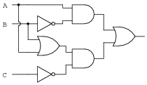
|
E
|
|
Notes:
For some reason, many of my students (who enter my course weak in algebra skills) generally seem to have a lot of trouble with factoring, be it Boolean algebra or regular algebra. This is unfortunate, as factoring is a powerful analytical tool. The "trick," if there is any such thing, is recognizing common variables in different product terms, and identifying which of them should be factored out to reduce the expression most efficiently.
Like all challenging things, factoring takes time and practice to learn. There are no shortcuts, really.
Hide Answer
Question 30:
Shown here are nine rules of Boolean algebra (these are not the only rules, of course).
-
�
-
A +[`A] = 1
-
�
- A + A = A
-
�
- A + 1 = 1
-
�
- AA = A
-
�
- A(1) = A
-
�
- A [`A] = 0
-
�
- A(B + C) = AB + AC
-
�
- A + AB = A
-
�
- A +[`A]B = A + B
Determine which rule is being used in each step of the following Boolean simplification:
Reveal Answer
Notes:
Quite frequently (and quite distressingly), I meet students who seem to have the most difficult time relating algebraic rules in their general form to specific instances of reduction. For example, a student who cannot tell that the rule A + AB = A applies to the expression QR + R, or worse yet B + AB. This skill requires time and hard work to master, because it is fundamentally a matter of abstraction: leaping from literal expressions to similar expressions, applying patterns from general rules to specific instances.
Questions such as this help students develop this abstraction ability. Let students explain how they "made the connection" between Boolean rules and the given reductions. Often, it helps to have a student explain the process to another student, because they are better able than you to put it into terms the struggling students can understand.
Hide Answer
Question 31:
Two very important rules of simplification in Boolean algebra are as follows:
-
�
-
Rule 1: A + AB = A
-
�
- Rule 2: A +[`A]B = A + B
Not only are these two rules confusingly similar, but many students find them difficult to successfully apply to situations where a Boolean expression uses different variables (letters), such as here:
Here, it is the first rule that applies (A + AB = A) and not the second rule (A +[
`A]B = A + B), giving a simplification of:
Try to apply these two rules to the following Boolean expressions, identifying which rule directly applies, or if neither rule directly applies:
-
�
-
FGH + G
-
�
- [`C] + CF
-
�
- [`AB]C + A
-
�
- RS +[`R]
-
�
- [`AB] + ABC
-
�
- [`AB]C + C
-
�
- [`R]V[`W] +[`R]
-
�
- [`X] [`Y] Z +[`XY]
-
�
- [`J] [`K] L M +[`J]K
-
�
- [`E]HF + F[`E]
Reveal Answer
-
�
-
FGH + G = G (Rule 1)
-
�
- [`C] + CF = [`C] + F (Rule 2)
-
�
- [`AB]C + A (Neither rule applies)
-
�
- RS +[`R] = [`R] + S (Rule 2)
-
�
- [`AB] + ABC = [`AB] + C (Rule 2)
-
�
- [`AB]C + C = C (Rule 1)
-
�
- [`R]V[`W] +[`R] = [`R] (Rule 1)
-
�
- [`X] [`Y] Z +[`XY] (Neither rule applies)
-
�
- [`J] [`K] L M +[`J]K (Neither rule applies)
-
�
- [`E]HF + F[`E] = [`E]F (Rule 1)
Notes:
Many students find the substitution of Boolean variables (going from the A's and B's of canonical rules to the different variables of real expressions where the rules are to be applied) very mysterious and difficult. Problems such as this give them practice learning to identify the rules' patterns despite similarities or differences in the actual variables (letters) used.
Hide Answer
Question 32:
Use Boolean algebra to simplify the following expression, then draw a logic gate circuit for the simplified expression:
Reveal Answer
Notes:
Have your students explain the entire process they used in answering this question: simplifying the expression using Boolean algebra techniques, and developing a gate circuit from the simplified Boolean expression. By having your students share their thought processes with the whole class, you will increase the level of learning on the parts of presenter and viewer alike. Students presenting their solutions will gain a better understanding of how it works because the act of presenting helps consolidate what they already know. Students viewing the presentation will get to see another person's technique (rather than just the instructor's), which will allow them to see examples of how to do these processes cast in slightly different terms.
Hide Answer
Question 33:
Use Boolean algebra to simplify the following expression, then draw a logic gate circuit for the simplified expression:
Reveal Answer
Challenge question: identify the specific logic gate type that will perform this Boolean function using just a single gate.
Notes:
Have your students explain the entire process they used in answering this question: simplifying the expression using Boolean algebra techniques, and developing a gate circuit from the simplified Boolean expression. By having your students share their thought processes with the whole class, you will increase the level of learning on the parts of presenter and viewer alike. Students presenting their solutions will gain a better understanding of how it works because the act of presenting helps consolidate what they already know. Students viewing the presentation will get to see another person's technique (rather than just the instructor's), which will allow them to see examples of how to do these processes cast in slightly different terms.
Hide Answer
Question 34:
Use Boolean algebra to simplify the following expression, then draw a logic gate circuit for the simplified expression:
|
|
A
|
|
B
|
|
C
|
+
|
A
|
|
B
|
C + A
|
B
|
|
C
|
+ A
|
B
|
C
|
|
Reveal Answer

Notes:
Have your students explain the entire process they used in answering this question: simplifying the expression using Boolean algebra techniques, and developing a gate circuit from the simplified Boolean expression. By having your students share their thought processes with the whole class, you will increase the level of learning on the parts of presenter and viewer alike. Students presenting their solutions will gain a better understanding of how it works because the act of presenting helps consolidate what they already know. Students viewing the presentation will get to see another person's technique (rather than just the instructor's), which will allow them to see examples of how to do these processes cast in slightly different terms.
Hide Answer
Question 35:
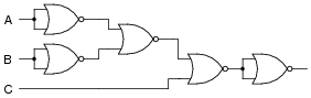
Use Boolean algebra to simplify the following logic gate circuit:
Reveal Answer
Notes:
Have your students explain the entire process they used in simplifying the gate circuit: developing the Boolean expression, simplifying that expression using Boolean algebra techniques, and then developing a new gate circuit from the simplified Boolean expression. By having your students share their thought processes with the whole class, you will increase the level of learning on the parts of presenter and viewer alike. Students presenting their solutions will gain a better understanding of how it works because the act of presenting helps consolidate what they already know. Students viewing the presentation will get to see another person's technique (rather than just the instructor's), which will allow them to see examples of how to do these processes cast in slightly different terms.
Hide Answer
Question 36:
Use Boolean algebra to simplify the following logic gate circuit:
Reveal Answer
Notes:
Have your students explain the entire process they used in simplifying the gate circuit: developing the Boolean expression, simplifying that expression using Boolean algebra techniques, and then developing a new gate circuit from the simplified Boolean expression. By having your students share their thought processes with the whole class, you will increase the level of learning on the parts of presenter and viewer alike. Students presenting their solutions will gain a better understanding of how it works because the act of presenting helps consolidate what they already know. Students viewing the presentation will get to see another person's technique (rather than just the instructor's), which will allow them to see examples of how to do these processes cast in slightly different terms.
Hide Answer
Question 37:
Use Boolean algebra to simplify the following logic gate circuit:
Reveal Answer
Notes:
Have your students explain the entire process they used in simplifying the gate circuit: developing the Boolean expression, simplifying that expression using Boolean algebra techniques, and then developing a new gate circuit from the simplified Boolean expression. By having your students share their thought processes with the whole class, you will increase the level of learning on the parts of presenter and viewer alike. Students presenting their solutions will gain a better understanding of how it works because the act of presenting helps consolidate what they already know. Students viewing the presentation will get to see another person's technique (rather than just the instructor's), which will allow them to see examples of how to do these processes cast in slightly different terms.
Hide Answer
Question 38:
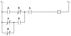
Use Boolean algebra to simplify the following relay (ladder logic) circuit:
Reveal Answer
Notes:
Have your students explain the entire process they used in simplifying the relay circuit: developing the Boolean expression, simplifying that expression using Boolean algebra techniques, and then developing a new relay circuit from the simplified Boolean expression. By having your students share their thought processes with the whole class, you will increase the level of learning on the parts of presenter and viewer alike. Students presenting their solutions will gain a better understanding of how it works because the act of presenting helps consolidate what they already know. Students viewing the presentation will get to see another person's technique (rather than just the instructor's), which will allow them to see examples of how to do these processes cast in slightly different terms.
Hide Answer
Question 39:
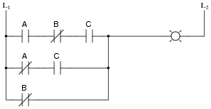
Use Boolean algebra to simplify the following relay (ladder logic) circuit:
Reveal Answer
Notes:
Have your students explain the entire process they used in simplifying the relay circuit: developing the Boolean expression, simplifying that expression using Boolean algebra techniques, and then developing a new relay circuit from the simplified Boolean expression. By having your students share their thought processes with the whole class, you will increase the level of learning on the parts of presenter and viewer alike. Students presenting their solutions will gain a better understanding of how it works because the act of presenting helps consolidate what they already know. Students viewing the presentation will get to see another person's technique (rather than just the instructor's), which will allow them to see examples of how to do these processes cast in slightly different terms.
Hide Answer
Question 40:
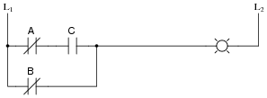
Use Boolean algebra to simplify the following relay (ladder logic) circuit:
Reveal Answer
Notes:
Have your students explain the entire process they used in simplifying the relay circuit: developing the Boolean expression, simplifying that expression using Boolean algebra techniques, and then developing a new relay circuit from the simplified Boolean expression. By having your students share their thought processes with the whole class, you will increase the level of learning on the parts of presenter and viewer alike. Students presenting their solutions will gain a better understanding of how it works because the act of presenting helps consolidate what they already know. Students viewing the presentation will get to see another person's technique (rather than just the instructor's), which will allow them to see examples of how to do these processes cast in slightly different terms.
Hide Answer
Question 41:
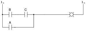
Use Boolean algebra to simplify the following relay (ladder logic) circuit:
Reveal Answer
Notes:
Have your students explain the entire process they used in simplifying the relay circuit: developing the Boolean expression, simplifying that expression using Boolean algebra techniques, and then developing a new relay circuit from the simplified Boolean expression. By having your students share their thought processes with the whole class, you will increase the level of learning on the parts of presenter and viewer alike. Students presenting their solutions will gain a better understanding of how it works because the act of presenting helps consolidate what they already know. Students viewing the presentation will get to see another person's technique (rather than just the instructor's), which will allow them to see examples of how to do these processes cast in slightly different terms.
Hide Answer
Question 42:
Complete truth tables for the following gates, and also write the Boolean expression for each gate:
The results should be obvious once the truth tables are both complete. Is there a general principle at work here? Do you think we would obtain similar results with Negative-OR and NAND gates? Explain.
Reveal Answer
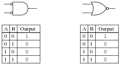
Negative-AND gate: [
`A] [
`B]
NOR gate: [
`(A + B)]
Notes:
Just a preview of DeMorgan's Theorem here!
Hide Answer
Question 43:
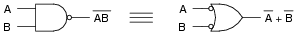
Often, we find extended complementation "bars" in Boolean expressions. A simple example is shown here, where a long bar extends over the Boolean expression A + B:
In this particular case, the expression represents the functionality of a NOR gate. Many times in the manipulation of Boolean expressions, it is good to be able to know how to eliminate such long bars. We can't just get rid of the bar, though. There are specific rules to follow for "breaking" long bars into smaller bars in Boolean expressions.
What other type of logic gate has the same functionality (the same truth table) as a NOR gate, and what is its equivalent Boolean expression? The answer to this question will demonstrate what rule(s) we need to follow when we "break" a long complementation bar in a Boolean expression.
Another example we could use for learning how to "break bars" in Boolean algebra is that of the NAND gate:
What other type of logic gate has the same functionality (the same truth table) as a NAND gate, and what is its equivalent Boolean expression? The answer to this question will likewise demonstrate what rule(s) we need to follow when we "break" a long complementation bar in a Boolean expression.
Reveal Answer
Negative-AND gates have the same functionality as NOR gates, and their equivalent Boolean expression is as such:
Negative-OR gates have the same functionality as NAND gates, and their equivalent Boolean expression is as such:
Notes:
This question introduces DeMorgan's Theorem via a process of discovery. Students, seeing that these equivalent gates pairs have the same functionality, should be able to discern a general pattern (i.e. a rule) for breaking long bars in Boolean expressions.
Hide Answer
Question 44:
What is
DeMorgan's Theorem?
Reveal Answer
DeMorgan's Theorem is a rule for Boolean expressions, declaring how long complementation "bars" are to be broken into shorter bars. I'll let you research the terms of this rule, and explain how to apply it to Boolean expressions.
Notes:
There are many suitable references for students to be able to learn DeMorgan's Theorem from. Let them do the research on their own! Your task is to clarify any misunderstandings after they've done their jobs.
Hide Answer
Question 45:
Use DeMorgan's Theorem, as well as any other applicable rules of Boolean algebra, to simplify the following expression so there are no more complementation bars extending over multiple variables:
Reveal Answer
Simplified expression:
Notes:
Have your students demonstrate exactly what they did (step by step) to simplify this expression, sharing their problem-solving strategies with the whole class.
Hide Answer
Question 46:
Use DeMorgan's Theorem, as well as any other applicable rules of Boolean algebra, to simplify the following expression so there are no more complementation bars extending over multiple variables:
Reveal Answer
Simplified expression:
Notes:
Have your students demonstrate exactly what they did (step by step) to simplify this expression, sharing their problem-solving strategies with the whole class.
Hide Answer
Question 47:
Use DeMorgan's Theorem, as well as any other applicable rules of Boolean algebra, to simplify the following expression so there are no more complementation bars extending over multiple variables:
Reveal Answer
Simplified expression:
|
(Expression is always equal to 1) |
|
Notes:
Have your students demonstrate exactly what they did (step by step) to simplify this expression, sharing their problem-solving strategies with the whole class.
Ask your students to determine what a non-variable solution means for a circuit such as this in a practical sense. What would they suspect if they tried to simplify a digital circuit and obtained this kind of result?
Hide Answer
Question 48:
Use Boolean algebra to simplify the following logic gate circuit:
Reveal Answer
Notes:
Have your students explain the entire process they used in simplifying the gate circuit: developing the Boolean expression, simplifying that expression using Boolean algebra techniques, and then developing a new gate circuit from the simplified Boolean expression. By having your students share their thought processes with the whole class, you will increase the level of learning on the parts of presenter and viewer alike. Students presenting their solutions will gain a better understanding of how it works because the act of presenting helps consolidate what they already know. Students viewing the presentation will get to see another person's technique (rather than just the instructor's), which will allow them to see examples of how to do these processes cast in slightly different terms.
Hide Answer
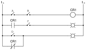
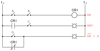
Question 49:
Write the Boolean expression for this relay logic circuit, then reduce that expression to its simplest form using any applicable Boolean laws and theorems. Finally, draw a new relay circuit based on the simplified Boolean expression that performs the exact same logic function.
Reveal Answer
Original Boolean expression: [
`([
`AB] + C)]
Reduced circuit (no relays needed!):
Notes:
Ask your students to explain what advantages there may be to using the simplified relay circuit rather than the original (more complex) relay circuit shown in the question. What significance does this lend to learning Boolean algebra?
This is what Boolean algebra is really for: reducing the complexity of logic circuits. It is far too easy for students to lose sight of this fact, learning all the abstract rules and laws of Boolean algebra. Remember, in teaching Boolean algebra, you are supposed to be preparing students to perform manipulations of electronic circuits, not just equations.
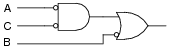
Hide Answer
Question 50:
Write the Boolean expression for this TTL logic gate circuit, then reduce that expression to its simplest form using any applicable Boolean laws and theorems. Finally, draw a new gate circuit diagram based on the simplified Boolean expression, that performs the exact same logic function.
Reveal Answer
Original Boolean expression: A +[
`([
`AB]C)]
Reduced gate circuit:
Challenge question: implement this reduced circuit, using the only remaining gates between the two integrated circuits shown on the original breadboard.
Notes:
Ask your students to explain what advantages there may be to using the simplified gate circuit rather than the original (more complex) gate circuit shown in the question. What significance does this lend to learning Boolean algebra?
This is what Boolean algebra is really for: reducing the complexity of logic circuits. It is far too easy for students to lose sight of this fact, learning all the abstract rules and laws of Boolean algebra. Remember, in teaching Boolean algebra, you are supposed to be preparing students to perform manipulations of electronic circuits, not just equations.
Hide Answer
Question 51:
A student makes a mistake somewhere in the process of simplifying the Boolean expression [
`([
`X]Y + Z)]. Determine what the mistake is:
Reveal Answer
The correct answer is:
If it is not apparent to you why the student's steps are in error, try this exercise: draw the equivalent gate circuit for each of the expressions written in the student's work. At the mistaken step, a dramatic change in the circuit configuration will be evident - a change that clearly cannot be correct. If all steps are proper, though, changes exhibited in the equivalent gate circuits should all make sense, culminating in a final (simplified) circuit.
Notes:
An important aspect of long "bars" for students to recognize is that they function as grouping symbols. When applying DeMorgan's Theorem to breaking these bars, students often make the mistake of ignoring the grouping implicit in the original bars.
I highly recommend you take your class through the exercise suggested in the answer, for those who do not understand the nature of the mistake. Let students draw each expression's equivalent circuit on the board in front of the class so everyone can see, and then let them observe the dramatic change spoken of at the place where the mistake is made. If students understand what DeMorgan's Theorem means for an individual gate (Neg-AND to NOR, Neg-OR to NAND, etc.), the gate diagrams will clearly reveal to them that something has gone wrong at that step.
For comparison, perform the same step-by-step translation of the proper Boolean simplification into gate diagrams. The transitions between diagrams will make far more sense, and students should be able to get a "circuit's view" of why complementation bars function as grouping symbols.
Hide Answer
Question 52:
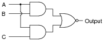
Write the Boolean expression for this TTL logic gate circuit, then reduce that expression to its simplest form using any applicable Boolean laws and theorems. Finally, draw a new gate circuit diagram based on the simplified Boolean expression that performs the exact same logic function.
Reveal Answer
Original Boolean expression: [
`(AB + AC)]
Reduced gate circuit:
Notes:
The Boolean simplification for this particular problem is tricky. Remind students that complementation bars act as grouping symbols, and that parentheses should be used when in doubt to maintain grouping after "breaking bars" with DeMorgan's Theorem.
Ask your students to compare the ßimplified" circuit with the original circuit. Are any advantages apparent to the version given in the answer? Certainly, the Boolean expression for that version of the circuit is simpler compared to that of the original circuit, but is the circuit itself significantly improved?
This question underscores an important lesson about Boolean algebra and logic simplification in general: just because a mathematical expression is simpler does not necessarily mean that the expression's physical realization will be any simpler than the original!
Hide Answer
Question 53:
Suppose you needed an inverter gate in a logic circuit, but none were available. You do, however, have a spare (unused) NAND gate in one of the integrated circuits. Show how you would connect a NAND gate to function as an inverter.
Use Boolean algebra to show that your solution is valid.
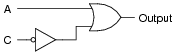
Reveal Answer

For the above solution: [
`AA] = [
`A]
Follow-up question: are there any other ways to use a NAND gate as an inverter? The method shown above is not the only valid solution!
Notes:
Not only is the method shown in the answer not the only valid solution, but it may even be the worst one! Your students should be able to research or invent alternative inverter connections, so after asking them to present their alternatives, ask the class as a whole to decide which solution is better. Ask them to consider electrical parameters, such as propagation delay time and fan-out.
Hide Answer
Question 54:
Suppose you needed an inverter gate in a logic circuit, but none were available. You do, however, have a spare (unused) NOR gate in one of the integrated circuits. Show how you would connect a NOR gate to function as an inverter.
Use Boolean algebra to show that your solution is valid.
Reveal Answer

For the above solution: [
`(A + A)] = [
`A]
Follow-up question: are there any other ways to use a NOR gate as an inverter? The method shown above is not the only valid solution!
Notes:
Not only is the method shown in the answer not the only valid solution, but it may even be the worst one! Your students should be able to research or invent alternative inverter connections, so after asking them to present their alternatives, ask the class as a whole to decide which solution is better. Ask them to consider electrical parameters, such as propagation delay time and fan-out.
Hide Answer
Question 55:
The equivalence between NAND gates and Negative-OR gates is something easily verified by an examination of these two gates' respective truth tables, and is often a starting-point for learning about DeMorgan's Theorem:
A lesser-known fact is how the equivalence between NAND and Negative-OR gates may be transformed to express an equivalence between two other types of gates, shown here:
Another example is shown here:
Explain how the first equivalence (between the NAND and the Negative-OR gate) was transformed into the latter two equivalences, both in terms of the gate symbols and their respective Boolean expressions. In other words, explain
how we can derive the last two examples by manipulating the first example.
Reveal Answer
This is a lot like algebraically manipulating equations: doing the exact same thing to both sides of an equation to arrive at a new equation that is more useful to us. I'll let you figure out the details of how this is done.
Notes:
This question is a precursor to having students create combinational gate circuits using nothing but NAND or NOR gates.
Hide Answer
Question 56:
Suppose we wished to have an AND gate for some logic purpose, but did not have any AND gates on hand. Instead, we only had NOR gates in our parts collection. Draw a diagram whereby multiple NOR gates are connected together to form an AND gate.
Reveal Answer
I'll let you figure this one out on your own!
Notes:
Hide Answer
Question 57:
NAND and NOR gates both have the interesting property of
universality. That is, it is possible to create any logic function at all, using nothing but multiple gates of either type. The key to doing this is DeMorgan's Theorem, because it shows us how properly applied inversion is able to convert between the two fundamental logic gate types (from AND to OR, and visa-versa).
Using this principle, convert the following gate circuit diagram into one built exclusively of NAND gates (no Boolean simplification, please). Then, do the same using nothing but NOR gates:
Reveal Answer
Using nothing but NAND gates:
Using nothing but NOR gates:
Notes:
Gate universality is not just an esoteric property of logic gates. There are (or at least were) entire logic systems made up of nothing but one of these gate types! I once worked with a fellow who maintained gas turbine control systems for crude oil pumping stations. He told me that he has seen one manufacturer's turbine control system where the discrete logic was nothing but NAND gates, and another manufacturer's system where the logic was nothing but NOR gates. Needless to say, it was a bit of a challenge for him to transition between the two manufacturers' systems, since it was natural for him to "get used to" one of the gate types after doing troubleshooting work on either type of system.
Hide Answer
Question 58:
An Exclusive-OR gate has the following Boolean expression:
Draw the schematic diagram for a gate circuit exhibiting this Boolean function, constructed entirely from NAND gates.
Reveal Answer
Notes:
An interesting feature of this circuit is the final three NAND gates: two NAND gates feeding into a third NAND gate is equivalent to two AND gates feeding into an OR gate, thanks to DeMorgan's Theorem!
Hide Answer
Question 59:
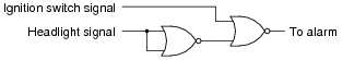
An automobile manufacturer needs a logic circuit to perform a specific task in its new line of cars. These cars will be equipped with a "headlight left on" alarm that sounds any time these two conditions are met: headlights on and ignition switch off. Draw the schematic diagram of a logic gate circuit that will implement this alarm, constructed entirely out of NAND gates.
Reveal Answer
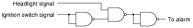
Follow-up question: suppose the alarm unit required more current than the final NAND gate could source. Add a transistor "buffer" stage to the logic gate circuit to drive additional current to the alarm.
Challenge question: explain how the following NOR gate circuit performs the exact same logic function with fewer components:
Notes:
This question is a really good one to ask your students how they arrived at a solution. It is easy enough to simply look at the given answer and repeat it, but of course the intent of this question is to get students to think how they might design such a circuit completely on their own.
Hide Answer
Question 60:
Draw a schematic for a logic gate circuit using nothing but two-input NOR gates that mimics the operation of this relay circuit:
Reveal Answer
Follow-up question: note the manner in which NOR gates are used as inverters in this circuit. Compare this against the following (alternative) method:
Are there any distinct advantages you see to either method?
Notes:
In my very first technical job, I worked as a CNC maintenance technician in a small machine shop, maintaining computer-controlled machine tools such as mills and lathes. A really neat project I got to work on at that job was the conversion of a 1970's era American-made machine tool to modern Japanese computer control. A lot of logic in that old machine tool was implemented using relays, and we replaced the cabinets full of relays with solid-state logic in the Japanese control computer. Actually, the solid state logic was a programmable logic controller or PLC function inside the Japanese control computer rather than discrete semiconductor logic gates. However, we very well could have replaced relays with hard-wired gates. The purpose of this question, if you haven't guessed by now, is to familiarize students with the concept of replacing electromechanical relays with semiconductor logic gates, especially identical logic gates such as NOR gates which are üniversal."
Hide Answer
Question 61:
Shown here is the ladder logic diagram for a fire alarm system, where the activation of any alarm switch opens that (normally-closed) switch contact and sounds the alarm:
Write the Boolean expression for this relay circuit, then simplify that expression using DeMorgan's Theorem and draw a new relay circuit implementing the simplified expression.
Reveal Answer
Original circuit expression:
Simplified expression and circuit:
Follow-up question: which circuit (the original or the one show above) is more practical from a fail-safe standpoint? In other words, which circuit will give the
safest result in the event of a switch or wiring failure?
Notes:
Here students see that even though two circuits are functionally identical (at least according to their respective Boolean expressions), they may not behave quite the same under adverse conditions (i.e. faulted switches or wiring). This is a very important thing for them to see, because it underscores the practical need to look beyond the immediate design criteria (Boolean function) and consider other parameters (failure mode).
Hide Answer
Question 62:
The
Law of Distribution in boolean algebra is identical to the law of distribution in "normal" algebra:
|
A(B + C) = AB + AC Applying the Law of Distribution |
|
While the process of distribution is not difficult to understand, the reverse of distribution (called
factoring) seems to be a more difficult process for many students to master:
|
AB + AC = A(B + C) Factoring A out of each term |
|
Survey the following examples of factoring, and then describe what this process entails. What pattern(s) are you looking for when trying to factor a Boolean expression?
|
CD + AD + BD = D(C + A + B)
|
|
|
X
|
Y
|
|
Z
|
+
|
X
|
|
Y
|
Z =
|
Y
|
(X
|
Z
|
+
|
X
|
Z)
|
|
|
AB + ABCD + BCD + B = B(A + ACD + CD + 1)
|
|
Reveal Answer
When factoring, you must look for variables
common to each product term.
Follow-up question: if implemented with digital logic gates, which of these two expressions would require the fewest components?
Notes:
Factoring really does seem to be a more difficult pattern-recognition skill to master than distribution, the latter being self-explanatory to many students. The purpose of this question is to get students to recognize and articulate the pattern-matching process involved with factoring. Once students have a working explanation of how to factor (especially if phrased in their own words), they will be better equipped to do so when needed.
Hide Answer
Question 63:
Simplify this logic gate circuit, which uses nothing but NAND gates to accomplish a certain logic function:
Reveal Answer
Notes:
This question stands as an example of how NAND gates may be used to construct different types of logic functions. In fact, with a sufficient quantity of NAND gates, any logic function may be built. This is why NAND gates are said to be üniversal."
Hide Answer
Question 64:
Simplify this logic gate circuit, which uses nothing but NOR gates to accomplish a certain logic function:
Reveal Answer
Notes:
This question stands as an example of how NOR gates may be used to construct different types of logic functions. In fact, with a sufficient quantity of NOR gates, any logic function may be built. This is why NOR gates are said to be üniversal."
Hide Answer
Question 65:
Sum-of-Products (SOP) expressions may be implemented by a combination of AND and OR gates, as such:
Use DeMorgan's Theorem to prove that this NAND gate circuit performs the exact same function:
Reveal Answer
I'll leave the proof up to you!
Notes:
This is a very practical application of DeMorgan's Theorem. Being able to use all NAND gates to implement an SOP function is a bonus over having to use separate AND and OR integrated circuit packages (one IC instead of two in this particular case).
Hide Answer
Question 66:
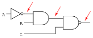
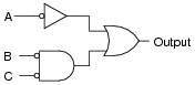
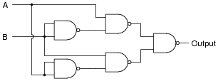
Write the Boolean expression for this logic gate circuit, then reduce that expression to its simplest form using any applicable Boolean laws and theorems. Finally, draw a new gate circuit diagram based on the simplified Boolean expression that performs the exact same logic function.
Reveal Answer
Original Boolean expression: [
`AB] [
`BC]
Reduced gate circuit:
Notes:
This particular circuit is an example of how a combinational logic function may be implemented using nothing but NAND gates.
Hide Answer
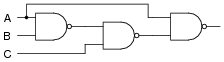
Question 67:
Write the Boolean expression for this logic gate circuit, then reduce that expression to its simplest form using any applicable Boolean laws and theorems. Finally, draw a new gate circuit diagram based on the simplified Boolean expression that performs the exact same logic function.
Reveal Answer
Original Boolean expression: [
`([
`([
`AB] C)] A)]
Reduced gate circuit:

Notes:
This particular circuit is an example of how a combinational logic function may be implemented using nothing but NAND gates.
Hide Answer