Calculus for electric circuits
Question 1:
Calculus is a branch of mathematics that originated with scientific questions concerning
rates of change. The easiest rates of change for most people to understand are those dealing with time. For example, a student watching their savings account dwindle over time as they pay for tuition and other expenses is very concerned with rates of change (
dollars per year being spent).
In calculus, we have a special word to describe rates of change:
derivative. One of the notations used to express a derivative (rate of change) appears as a fraction. For example, if the variable S represents the amount of money in the student's savings account and t represents time, the rate of change of dollars over time would be written like this:
The following set of figures puts actual numbers to this hypothetical scenario:
-
�
-
Date: November 20
-
�
- Saving account balance (S) = $12,527.33
-
�
- Rate of spending ([dS/dt]) = -5,749.01 per year
List some of the equations you have seen in your study of electronics containing derivatives, and explain how
rate of change relates to the real-life phenomena described by those equations.
Reveal Answer
Voltage and current for a capacitor:
Voltage and current for an inductor:
Electromagnetic induction:
I leave it to you to describe how the rate-of-change over time of one variable relates to the other variables in each of the scenarios described by these equations.
Follow-up question: why is the derivative quantity in the student's savings account example expressed as a negative number? What would a positive [dS/dt] represent in real life?
Challenge question: describe actual circuits you could build to demonstrate each of these equations, so that others could see what it means for one variable's rate-of-change over time to affect another variable.
Notes:
The purpose of this question is to introduce the concept of the derivative to students in ways that are familiar to them. Hopefully the opening scenario of a dwindling savings account is something they can relate to!
A very important aspect of this question is the discussion it will engender between you and your students regarding the relationship between rates of change in the three equations given in the answer. It is very important to your students' comprehension of this concept to be able to verbally describe how the derivative works in each of these formulae. You may want to have them phrase their responses in realistic terms, as if they were describing how to set up an illustrative experiment for a classroom demonstration.
Hide Answer
Question 2:
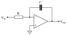
According to the Öhm's Law" formula for a capacitor, capacitor current is proportional to the
time-derivative of capacitor voltage:
Another way of saying this is to state that the capacitors
differentiate voltage with respect to time, and express this
time-derivative of voltage as a current.
Suppose we had an oscilloscope capable of directly measuring current, or at least a current-to-voltage converter that we could attach to one of the probe inputs to allow direct measurement of current on one channel. With such an instrument set-up, we could directly plot capacitor voltage and capacitor current together on the same display:
For each of the following voltage waveforms (channel B), plot the corresponding capacitor current waveform (channel A) as it would appear on the oscilloscope screen:
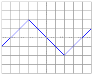
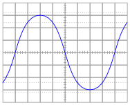
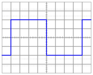
Note: the amplitude of your current plots is arbitrary. What I'm interested in here is the
shape of each current waveform!
Reveal Answer
Follow-up question: what electronic device could perform the function of a "current-to-voltage converter" so we could use an oscilloscope to measure capacitor current? Be as specific as you can in your answer.
Notes:
Here, I ask students to relate the instantaneous rate-of-change of the voltage waveform to the instantaneous amplitude of the current waveform. Just a conceptual exercise in derivatives.
Hide Answer
Question 3:
Potentiometers are very useful devices in the field of robotics, because they allow us to represent the position of a machine part in terms of a voltage. In this particular case, a potentiometer mechanically linked to the joint of a robotic arm represents that arm's angular position by outputting a corresponding voltage signal:
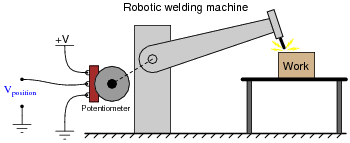
As the robotic arm rotates up and down, the potentiometer wire moves along the resistive strip inside, producing a voltage directly proportional to the arm's position. A voltmeter connected between the potentiometer wiper and ground will then indicate arm position. A computer with an analog input port connected to the same points will be able to measure, record, and (if also connected to the arm's motor drive circuits) control the arm's position.
If we connect the potentiometer's output to a
differentiator circuit, we will obtain another signal representing something else about the robotic arm's action. What physical variable does the differentiator output signal represent?
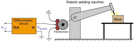
Reveal Answer
The differentiator circuit's output signal represents the angular
velocity of the robotic arm, according to the following equation:
Where,
v = velocity
x = position
t = time
Follow-up question: what type of signal will we obtain if we differentiate the position signal twice (i.e. connect the output of the first differentiator circuit to the input of a second differentiator circuit)?
Notes:
This question asks students to relate the concept of time-differentiation to physical motion, as well as giving them a very practical example of how a passive differentiator circuit could be used. In reality, one must be very careful to use differentiator circuits for real-world signals because differentiators tend to amplify high-frequency noise. Since real-world signals are often "noisy," this leads to a lot of noise in the differentiated signals.
Hide Answer
Question 4:
One of the fundamental principles of calculus is a process called
integration. This principle is important to understand because it is manifested in the behavior of capacitance. Thankfully, there are more familiar physical systems which also manifest the process of integration, making it easier to comprehend.
If we introduce a constant flow of water into a cylindrical tank with water, the water level inside that tank will rise at a constant rate over time:
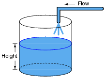
In calculus terms, we would say that the tank
integrates water flow into water height. That is, one quantity (flow) dictates the rate-of-change over time of another quantity (height).
Like the water tank, electrical
capacitance also exhibits the phenomenon of integration with respect to time. Which electrical quantity (voltage or current) dictates the rate-of-change over time of which other quantity (voltage or current) in a capacitance? Or, to re-phrase the question, which quantity (voltage or current), when maintained at a constant value, results in which other quantity (current or voltage) steadily ramping either up or down over time?
Reveal Answer
In a capacitance, voltage is the time-integral of current. That is, the applied current "through" the capacitor dictates the rate-of-change of voltage across the capacitor over time.
Challenge question: can you think of a way we could exploit the similarity of capacitive voltage/current integration to
simulate the behavior of a water tank's filling, or any other physical process described by the same mathematical relationship?
Notes:
The concept of integration doesn't have to be overwhelmingly complex. Electrical phenomena such as capacitance and inductance may serve as excellent contexts in which students may explore and comprehend the abstract principles of calculus. The amount of time you choose to devote to a discussion of this question will depend on how mathematically adept your students are.
Hopefully, the challenge question will stir your students' imaginations, as they realize the usefulness of electrical components as analogues for other types of physical systems.
Hide Answer
Question 5:
One of the fundamental principles of calculus is a process called
integration. This principle is important to understand because it is manifested in the behavior of inductance. Thankfully, there are more familiar physical systems which also manifest the process of integration, making it easier to comprehend.
If we introduce a constant flow of water into a cylindrical tank with water, the water level inside that tank will rise at a constant rate over time:

In calculus terms, we would say that the tank
integrates water flow into water height. That is, one quantity (flow) dictates the rate-of-change over time of another quantity (height).
Like the water tank, electrical
inductance also exhibits the phenomenon of integration with respect to time. Which electrical quantity (voltage or current) dictates the rate-of-change over time of which other quantity (voltage or current) in an inductance? Or, to re-phrase the question, which quantity (voltage or current), when maintained at a constant value, results in which other quantity (current or voltage) steadily ramping either up or down over time?
Reveal Answer
In an inductance, current is the time-integral of voltage. That is, the applied voltage across the inductor dictates the rate-of-change of current through the inductor over time.
Challenge question: can you think of a way we could exploit the similarity of inductive voltage/current integration to
simulate the behavior of a water tank's filling, or any other physical process described by the same mathematical relationship?
Notes:
The concept of integration doesn't have to be overwhelmingly complex. Electrical phenomena such as capacitance and inductance may serve as excellent contexts in which students may explore and comprehend the abstract principles of calculus. The amount of time you choose to devote to a discussion of this question will depend on how mathematically adept your students are.
Hide Answer
Question 6:
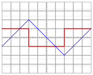
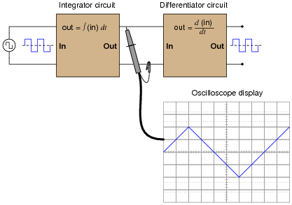
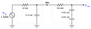
Both the input and the output of this circuit are square waves, although the output waveform is slightly distorted and also has much less amplitude:
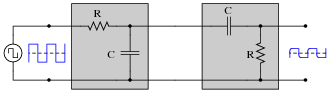
You recognize one of the RC networks as a passive integrator, and the other as a passive differentiator. What does the likeness of the output waveform compared to the input waveform indicate to you about differentiation and integration as
functions applied to waveforms?
Reveal Answer
Differentiation and integration are mathematically inverse functions of one another. With regard to waveshape, either function is reversible by subsequently applying the other function.
Follow-up question: this circuit will not work as shown if both R values are the same, and both C values are the same as well. Explain why, and also describe what value(s) would have to be different to allow the original square-waveshape to be recovered at the final output terminals.
Notes:
That integration and differentiation are inverse functions will probably be obvious already to your more mathematically inclined students. To others, it may be a revelation.
If time permits, you might want to elaborate on the limits of this complementarity. As anyone with calculus background knows, integration introduces an arbitrary constant of integration. So, if the integrator stage follows the differentiator stage, there may be a DC bias added to the output that is not present in the input (or visa-versa!).
|
|
�
�
|
|
d
dx
|
[ f(x) ] dx = f(x) + C
|
|
In a circuit such as this where integration precedes differentiation, ideally there is no DC bias (constant) loss:
|
|
d
dx
|
|
�
�
|
�
�
|
f(x) dx
|
�
�
|
= f(x)
|
|
However, since these are actually first-order "lag" and "lead" networks rather than true integration and differentiation stages, respectively, a DC bias applied to the input will
not be faithfully reproduced on the output. Whereas a true integrator would take a DC bias input and produce an output with a linearly ramping bias, a passive integrator will assume an output bias equal to the input bias.
f Therefore, the subsequent differentiation stage, perfect or not, has no slope to differentiate, and thus there will be no DC bias on the output.
Incidentally, the following values work well for a demonstration circuit:
Footnotes:
f If this is not apparent to you, I suggest performing Superposition analysis on a passive integrator (consider AC, then consider DC separately), and verify that V
DC(out) = V
DC(in). A passive differentiator circuit would have to possess an infinite time constant (
t =
�) in order to generate this ramping output bias!
Hide Answer
Question 7:
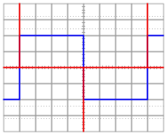
Determine what the response will be to a constant DC voltage applied at the input of these (ideal) circuits:
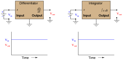
Reveal Answer
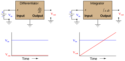
Notes:
Ask your students to frame their answers in a practical context, such as speed and distance for a moving object (where speed is the time-derivative of distance and distance is the time-integral of speed).
Hide Answer
Question 8:
In calculus, differentiation is the
inverse operation of something else called
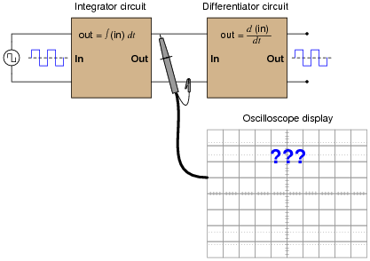
integration. That is to say, differentiation ün-does" integration to arrive back at the original function (or signal). To illustrate this electronically, we may connect a differentiator circuit to the output of an integrator circuit and (ideally) get the exact same signal out that we put in:
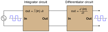
Based on what you know about differentiation and differentiator circuits, what must the signal look like in between the integrator and differentiator circuits to produce a final square-wave output? In other words, if we were to connect an oscilloscope in between these two circuits, what sort of signal would it show us?
Reveal Answer
Follow-up question: what do the schematic diagrams of passive integrator and differentiator circuits look like? How are they similar to one another and how do they differ?
Notes:
This question introduces students to the concept of integration, following their prior familiarity with differentiation. Since they should already be familiar with other examples of inverse mathematical functions (arcfunctions in trigonometry, logs and powers, squares and roots, etc.), this should not be too much of a stretch. The fact that we may show them the cancellation of integration with differentiation should be proof enough.
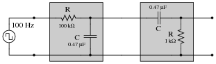
In case you wish to demonstrate this principle "live" in the classroom, I suggest you bring a signal generator and oscilloscope to the class, and build the following circuit on a breadboard:
The output is not a perfect square wave, given the loading effects of the differentiator circuit on the integrator circuit, and also the imperfections of each operation (being passive rather than active integrator and differentiator circuits). However, the wave-shapes are clear enough to illustrate the basic concept.
Hide Answer
Question 9:
Plot the relationships between voltage and current for resistors of three different values (1
W, 2
W, and 3
W), all on the same graph:
What pattern do you see represented by your three plots? What relationship is there between the amount of resistance and the nature of the voltage/current function as it appears on the graph?
Advanced question: in calculus, the instantaneous rate-of-change of an (x,y) function is expressed through the use of the
derivative notation: [dy/dx]. How would the derivative for each of these three plots be properly expressed using calculus notation? Explain how the derivatives of these functions relate to real electrical quantities.
Reveal Answer
The greater the resistance, the steeper the slope of the plotted line.
Advanced answer: the proper way to express the derivative of each of these plots is [dv/di]. The derivative of a linear function is a constant, and in each of these three cases that constant equals the resistor resistance in ohms. So, we could say that for simple resistor circuits, the instantaneous rate-of-change for a voltage/current function
is the resistance of the circuit.
Notes:
Students need to become comfortable with graphs, and creating their own simple graphs is an excellent way to develop this understanding. A graphical representation of the Ohm's Law function allows students another "view" of the concept, allowing them to more easily understand more advanced concepts such as negative resistance.
If students have access to either a graphing calculator or computer software capable of drawing 2-dimensional graphs, encourage them to plot the functions using these technological resources.
I have found it a good habit to ßneak" mathematical concepts into physical science courses whenever possible. For so many people, math is an abstract and confusing subject, which may be understood only in the context of real-life application. The studies of electricity and electronics are rich in mathematical context, so exploit it whenever possible! Your students will greatly benefit.
Hide Answer
Question 10:
Ohm's Law tells us that the amount of current through a fixed resistance may be calculated as such:
We could also express this relationship in terms of
conductance rather than
resistance, knowing that G =
1/
R:
However, the relationship between current and voltage for a fixed capacitance is quite different. The Öhm's Law" formula for a capacitor is as such:
What significance is there in the use of lower-case variables for current (i) and voltage (e)? Also, what does the expression [de/dt] mean? Note: in case you think that the d's are variables, and should cancel out in this fraction, think again: this is no ordinary quotient! The d letters represent a calculus concept known as a
differential, and a quotient of two d terms is called a
derivative.
Reveal Answer
Lower-case variables represent
instantaneous values, as opposed to average values. The expression [de/dt], which may also be written as [dv/dt], represents the
instantaneous rate of change of voltage over time.
Follow-up question: manipulate this equation to solve for the other two variables ([de/dt] =
� ; C =
�).
Notes:
I have found that the topics of capacitance and inductance are excellent contexts in which to introduce fundamental principles of calculus to students. The time you spend discussing this question and questions like it will vary according to your students' mathematical abilities.
Even if your students are not ready to explore calculus, it is still a good idea to discuss how the relationship between current and voltage for a capacitance involves time. This is a radical departure from the time-independent nature of resistors, and of Ohm's Law!
Hide Answer
Question 11:
Capacitors store energy in the form of an electric field. We may calculate the energy stored in a capacitance by integrating the product of capacitor voltage and capacitor current (P = IV) over time, since we know that power is the rate at which work (W) is done, and the amount of work done to a capacitor taking it from zero voltage to some non-zero amount of voltage constitutes energy stored (U):
Find a way to substitute capacitance (C) and voltage (V) into the integrand so you may integrate to find an equation describing the amount of energy stored in a capacitor for any given capacitance and voltage values.
Reveal Answer
Notes:
The integration required to obtain the answer is commonly found in calculus-based physics textbooks, and is an easy (power rule) integration.
Hide Answer
Question 12:
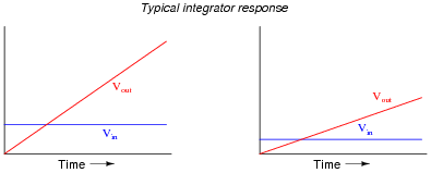
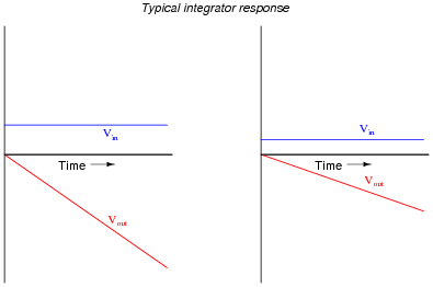
Integrator circuits may be understood in terms of their response to DC input signals: if an integrator receives a steady, unchanging DC input voltage signal, it will output a voltage that changes with a steady
rate over time. The rate of the changing output voltage is directly proportional to the magnitude of the input voltage:
A symbolic way of expressing this input/output relationship is by using the concept of the
derivative in calculus (a rate of change of one variable compared to another). For an integrator circuit, the rate of output voltage change over time is proportional to the input voltage:
A more sophisticated way of saying this is, "The time-derivative of output voltage is proportional to the input voltage in an integrator circuit." However, in calculus there is a special symbol used to express this same relationship in reverse terms: expressing the output voltage as a function of the input. For an integrator circuit, this special symbol is called the
integration symbol, and it looks like an elongated letter "S":
Here, we would say that output voltage is proportional to the time-integral of the input voltage, accumulated over a period of time from time=0 to some point in time we call T.
"This is all very interesting," you say, "but what does this have to do with anything in real life?" Well, there are actually a great deal of applications where physical quantities are related to each other by time-derivatives and time-integrals. Take this water tank, for example:

One of these variables (either height H or flow F, I'm not saying yet!) is the time-integral of the other, just as V
out is the time-integral of V
in in an integrator circuit. What this means is that we could electrically measure one of these two variables in the water tank system (either height or flow) so that it becomes represented as a voltage, then send that voltage signal to an integrator and have the output of the integrator
derive the other variable in the system without having to measure it!
Your task is to determine which variable in the water tank scenario would have to be measured so we could electronically predict the other variable using an integrator circuit.
Reveal Answer
Flow (F) is the variable we would have to measure, and that the integrator circuit would time-integrate into a height prediction.
Notes:
Your more alert students will note that the output voltage for a simple integrator circuit is of inverse polarity with respect to the input voltage, so the graphs should really look like this:
I have chosen to express all variables as positive quantities in order to avoid any unnecessary confusion as students attempt to grasp the concept of time integration.
Hide Answer
Question 13:
We know that the output of an integrator circuit is proportional to the time-integral of the input voltage:
But how do we turn this proportionality into an exact equality, so that it accounts for the values of R and C? Although the answer to this question is easy enough to simply look up in an electronics reference book, it would be great to actually derive the exact equation from your knowledge of electronic component behaviors! Here are a couple of hints:
Reveal Answer
|
Vout = - |
1
RC
|
|
�
�
|
T
0
|
Vin dt
|
|
Follow-up question: why is there a negative sign in the equation?
Notes:
The two "hint" equations given at the end of the question beg for algebraic substitution, but students must be careful which variable(s) to substitute! Both equations contain an I, and both equations also contain a V. The answer to that question can only be found by looking at the schematic diagram: do the resistor and capacitor share the same current, the same voltage, or both?
Hide Answer
Question 14:
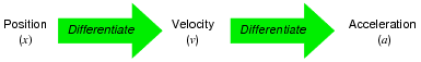
If an object moves in a straight line, such as an automobile traveling down a straight road, there are three common measurements we may apply to it:
position (x),
velocity (v), and
acceleration (a). Position, of course, is nothing more than a measure of how far the object has traveled from its starting point. Velocity is a measure of how
fast its position is changing over time. Acceleration is a measure of how fast the velocity is changing over time.
These three measurements are excellent illustrations of calculus in action. Whenever we speak of "rates of change," we are really referring to what mathematicians call
derivatives. Thus, when we say that velocity (v) is a measure of how fast the object's position (x) is changing over time, what we are really saying is that velocity is the "time-derivative" of position. Symbolically, we would express this using the following notation:
Likewise, if acceleration (a) is a measure of how fast the object's velocity (v) is changing over time, we could use the same notation and say that acceleration is the time-derivative of velocity:
Since it took two differentiations to get from position to acceleration, we could also say that acceleration is the
second time-derivative of position:
"What has this got to do with electronics," you ask? Quite a bit! Suppose we were to measure the velocity of an automobile using a tachogenerator sensor connected to one of the wheels: the faster the wheel turns, the more DC voltage is output by the generator, so that voltage becomes a direct representation of velocity. Now we send this voltage signal to the input of a
differentiator circuit, which performs the time-differentiation function on that signal. What would the output of this differentiator circuit then represent with respect to the automobile,
position or
acceleration? What practical use do you see for such a circuit?
Now suppose we send the same tachogenerator voltage signal (representing the automobile's velocity) to the input of an
integrator circuit, which performs the time-integration function on that signal (which is the mathematical inverse of differentiation, just as multiplication is the mathematical inverse of division). What would the output of this integrator then represent with respect to the automobile,
position or
acceleration? What practical use do you see for such a circuit?
Reveal Answer
The differentiator's output signal would be proportional to the automobile's
acceleration, while the integrator's output signal would be proportional to the automobile's
position.
|
a � |
dv
dt
|
Output of differentiator |
|
|
x � |
�
�
|
T
0
|
v dt Output of integrator |
|
Follow-up question: draw the schematic diagrams for these two circuits (differentiator and integrator).
Notes:
The calculus relationships between position, velocity, and acceleration are fantastic examples of how time-differentiation and time-integration works, primarily because everyone has first-hand, tangible experience with all three. Everyone inherently understands the relationship between distance, velocity, and time, because everyone has had to travel somewhere at some point in their lives. Whenever you as an instructor can help bridge difficult conceptual leaps by appeal to common experience, do so!
Hide Answer
Question 15:
A familiar context in which to apply and understand basic principles of calculus is the motion of an object, in terms of
position (x),
velocity (v), and
acceleration (a). We know that velocity is the time-derivative of position (v = [dx/dt]) and that acceleration is the time-derivative of velocity (a = [dv/dt]). Another way of saying this is that velocity is the rate of position change over time, and that acceleration is the rate of velocity change over time.
It is easy to construct circuits which input a voltage signal and output either the
time-derivative or the
time-integral (the opposite of the derivative) of that input signal. We call these circuits "differentiators" and ïntegrators," respectively.
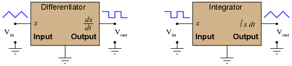
Integrator and differentiator circuits are highly useful for motion signal processing, because they allow us to take voltage signals from motion sensors and convert them into signals representing other motion variables. For each of the following cases, determine whether we would need to use an integrator circuit or a differentiator circuit to convert the first type of motion signal into the second:
-
�
-
Converting velocity signal to position signal: (integrator or differentiator?)
-
�
- Converting acceleration signal to velocity signal: (integrator or differentiator?)
-
�
- Converting position signal to velocity signal: (integrator or differentiator?)
-
�
- Converting velocity signal to acceleration signal: (integrator or differentiator?)
-
�
- Converting acceleration signal to position signal: (integrator or differentiator?)
Also, draw the schematic diagrams for these two different circuits.
Reveal Answer
-
�
-
Converting velocity signal to position signal: (integrator)
-
�
- Converting acceleration signal to velocity signal: (integrator)
-
�
- Converting position signal to velocity signal: (differentiator)
-
�
- Converting velocity signal to acceleration signal: (differentiator)
-
�
- Converting acceleration signal to position signal: (two integrators!)
I'll let you figure out the schematic diagrams on your own!
Notes:
The purpose of this question is to have students apply the concepts of time-integration and time-differentiation to the variables associated with moving objects. I like to use the context of moving objects to teach basic calculus concepts because of its everyday familiarity: anyone who has ever driven a car knows what position, velocity, and acceleration are, and the differences between them.
One way I like to think of these three variables is as a verbal sequence:

Arranged as shown, differentiation is the process of stepping to the right (measuring the
rate of change of the previous variable). Integration, then, is simply the process of stepping to the left.
Ask your students to come to the front of the class and draw their integrator and differentiator circuits. Then, ask the whole class to think of some scenarios where these circuits would be used in the same manner suggested by the question: motion signal processing. Having them explain how their schematic-drawn circuits would work in such scenarios will do much to strengthen their grasp on the concept of practical integration and differentiation.
Hide Answer
Question 16:
We know that the output of a differentiator circuit is proportional to the time-derivative of the input voltage:
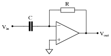
But how do we turn this proportionality into an exact equality, so that it accounts for the values of R and C? Although the answer to this question is easy enough to simply look up in an electronics reference book, it would be great to actually derive the exact equation from your knowledge of electronic component behaviors! Here are a couple of hints:
Reveal Answer
|
Vout = - RC
|
�
�
|
dVin
dt
|
�
�
|
|
|
Follow-up question: why is there a negative sign in the equation?
Notes:
The two "hint" equations given at the end of the question beg for algebraic substitution, but students must be careful which variable(s) to substitute! Both equations contain an I, and both equations also contain a V. The answer to that question can only be found by looking at the schematic diagram: do the resistor and capacitor share the same current, the same voltage, or both?
Hide Answer
Question 17:
You are part of a team building a rocket to carry research instruments into the high atmosphere. One of the variables needed by the on-board flight-control computer is velocity, so it can throttle engine power and achieve maximum fuel efficiency. The problem is, none of the electronic sensors on board the rocket has the ability to directly measure velocity. What is available is an
altimeter, which infers the rocket's altitude (it position away from ground) by measuring ambient air pressure; and also an
accelerometer, which infers acceleration (rate-of-change of velocity) by measuring the inertial force exerted by a small mass.
The lack of a ßpeedometer" for the rocket may have been an engineering design oversight, but it is still your responsibility as a development technician to figure out a workable solution to the dilemma. How do you propose we obtain the electronic velocity measurement the rocket's flight-control computer needs?
Reveal Answer
One possible solution is to use an electronic
integrator circuit to derive a velocity measurement from the accelerometer's signal. However, this is not the only possible solution!
Notes:
This question simply puts students' comprehension of basic calculus concepts (and their implementation in electronic circuitry) to a practical test.
Hide Answer
Question 18:
A
Rogowski Coil is essentially an air-core current transformer that may be used to measure DC currents as well as AC currents. Like all current transformers, it measures the current going through whatever conductor(s) it encircles.
Normally transformers are considered AC-only devices, because electromagnetic induction requires a
changing magnetic field ([(d
f)/dt]) to induce voltage in a conductor. The same is true for a Rogowski coil: it produces a voltage only when there is a change in the measured current. However, we may measure any current (DC or AC) using a Rogowski coil if its output signal feeds into an integrator circuit as shown:
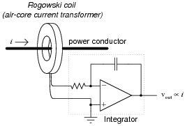
Connected as such, the output of the integrator circuit will be a direct representation of the amount of current going through the wire.
Explain why an integrator circuit is necessary to condition the Rogowski coil's output so that output voltage truly represents conductor current.
Reveal Answer
The coil produces a voltage proportional to the conductor current's rate of change over time (v
coil = M [di/dt]). The integrator circuit produces an output voltage changing at a rate proportional to the input voltage magnitude ([(dv
out)/dt]
� v
in). Substituting algebraically:
Review question: Rogowski coils are rated in terms of their
mutual inductance (M). Define what "mutual inductance" is, and why this is an appropriate parameter to specify for a Rogowski coil.
Follow-up question: the operation of a Rogowski coil (and the integrator circuit) is probably easiest to comprehend if one imagines the measured current starting at 0 amps and linearly increasing over time. Qualitatively explain what the coil's output would be in this scenario and then what the integrator's output would be.
Challenge question: the integrator circuit shown here is an äctive" integrator rather than a "passive" integrator. That is, it contains an amplifier (an äctive" device). We could use a passive integrator circuit instead to condition the output signal of the Rogowski coil, but only if the measured current is purely AC. A passive integrator circuit would be insufficient for the task if we tried to measure a DC current - only an active integrator would be adequate to measure DC. Explain why.
Notes:
This question provides a great opportunity to review Faraday's Law of electromagnetic induction, and also to apply simple calculus concepts to a practical problem. The coil's natural function is to differentiate the current going through the conductor, producing an output voltage proportional to the current's rate of change over time (vout � [(diin)/dt]). The integrator's function is just the opposite. Discuss with your students how the integrator circuit ündoes" the natural calculus operation inherent to the coil (differentiation).
The subject of Rogowski coils also provides a great opportunity to review what mutual inductance is. Usually introduced at the beginning of lectures on transformers and quickly forgotten, the principle of mutual inductance is at the heart of every Rogowski coil: the coefficient relating instantaneous current change through one conductor to the voltage induced in an adjacent conductor (magnetically linked).
Unlike the iron-core current transformers (CT's) widely used for AC power system current measurement, Rogowski coils are inherently linear. Being air-core devices, they lack the potential for saturation, hysteresis, and other nonlinearities which may corrupt the measured current signal. This makes Rogowski coils well-suited for high frequency (even RF!) current measurements, as well as measurements of current where there is a strong DC bias current in the conductor. By the way, this DC bias current may be "nulled" simply by re-setting the integrator after the initial DC power-up!
If time permits, this would be an excellent point of departure to other realms of physics, where op-amp signal conditioning circuits can be used to ündo" the calculus functions inherent to certain physical measurements (acceleration vs. velocity vs. position, for example).
Hide Answer
Question 19:
A Rogowski coil has a mutual inductance rating of 5
mH. Calculate the size of the resistor necessary in the integrator circuit to give the integrator output a 1:1 scaling with the measured current, given a capacitor size of 4.7 nF:
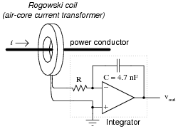
That is, size the resistor such that a current through the conductor changing at a rate of 1 amp per second will generate an integrator output voltage changing at a rate of 1 volt per second.
Reveal Answer
R = 1.064 k
W
Notes:
This question not only tests students' comprehension of the Rogowski coil and its associated calculus (differentiating the power conductor current, as well as the need to integrate its output voltage signal), but it also tests students' quantitative comprehension of integrator circuit operation and problem-solving technique. Besides, it gives some practical context to integrator circuits!
Hide Answer
Question 20:
The
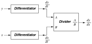
chain rule of calculus states that:
Similarly, the following mathematical principle is also true:
It is very easy to build an opamp circuit that differentiates a voltage signal with respect to
time, such that an input of x produces an output of [dx/dt], but there is no simple circuit that will output the differential of one input signal with respect to a second input signal.
However, this does not mean that the task is impossible. Draw a block diagram for a circuit that calculates [dy/dx], given the input voltages x and y. Hint: this circuit will make use of differentiators.
Challenge question: draw a full opamp circuit to perform this function!
Reveal Answer
Notes:
Differentiator circuits are very useful devices for making "live" calculations of time-derivatives for variables represented in voltage form. Explain to your students, for example, that the physical measurement of velocity, when differentiated with respect to time, is acceleration. Thus, a differentiator circuit connected to a tachogenerator measuring the speed of something provides a voltage output representing acceleration.
Being able to differentiate one signal in terms of another, although equally useful in physics, is not so easy to accomplish with opamps. A question such as this one highlights a practical use of calculus (the "chain rule"), where the differentiator circuit's natural function is exploited to achieve a more advanced function.
Hide Answer
Question 21:
Ohm's Law tells us that the amount of voltage dropped by a fixed resistance may be calculated as such:
However, the relationship between voltage and current for a fixed inductance is quite different. The Öhm's Law" formula for an inductor is as such:
What significance is there in the use of lower-case variables for current (i) and voltage (e)? Also, what does the expression [di/dt] mean? Note: in case you think that the d's are variables, and should cancel out in this fraction, think again: this is no ordinary quotient! The d letters represent a calculus concept known as a
differential, and a quotient of two d terms is called a
derivative.
Reveal Answer
Lower-case variables represent
instantaneous values, as opposed to average values. The expression [di/dt] represents the
instantaneous rate of change of current over time.
Follow-up question: manipulate this equation to solve for the other two variables ([di/dt] =
� ; L =
�).
Notes:
I have found that the topics of capacitance and inductance are excellent contexts in which to introduce fundamental principles of calculus to students. The time you spend discussing this question and questions like it will vary according to your students' mathematical abilities.
Even if your students are not ready to explore calculus, it is still a good idea to discuss how the relationship between current and voltage for an inductance involves time. This is a radical departure from the time-independent nature of resistors, and of Ohm's Law!
Hide Answer
Question 22:
Digital logic circuits, which comprise the inner workings of computers, are essentially nothing more than arrays of switches made from semiconductor components called
transistors. As switches, these circuits have but two states: on and off, which represent the binary states of 1 and 0, respectively.
The faster these switch circuits are able to change state, the faster the computer can perform arithmetic and do all the other tasks computers do. To this end, computer engineers keep pushing the limits of transistor circuit design to achieve faster and faster switching rates.
This race for speed causes problems for the power supply circuitry of computers, though, because of the current ßurges" (technically called
transients) created in the conductors carrying power from the supply to the logic circuits. The faster these logic circuits change state, the greater the [di/dt] rates-of-change exist in the conductors carrying current to power them. Significant voltage drops can occur along the length of these conductors due to their parasitic inductance:
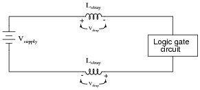
Suppose a logic gate circuit creates transient currents of 175 amps per nanosecond (175 A/ns) when switching from the öff" state to the ön" state. If the total inductance of the power supply conductors is 10 picohenrys (9.5 pH), and the power supply voltage is 5 volts DC, how much voltage remains at the power terminals of the logic gate during one of these ßurges"?
Reveal Answer
Voltage remaining at logic gate terminals during current transient = 3.338 V
Notes:
Students will likely marvel at the [di/dt] rate of 175 amps per nanosecond, which equates to 175 billion amps per second. Not only is this figure realistic, though, it is also low by some estimates (see IEEE Spectrum magazine, July 2003, Volume 40, Number 7, in the article "Putting Passives In Their Place"). Some of your students may be very skeptical of this figure, not willing to believe that ä computer power supply is capable of outputting 175 billion amps?!"
This last statement represents a very common error students commit, and it is based on a fundamental misunderstanding of [di/dt]. "175 billion amps per second" is not the same thing as "175 billion amps". The latter is an absolute measure, while the former is a rate of change over time. It is the difference between saying "1500 miles per hour" and "1500 miles". Just because a bullet travels at 1500 miles per hour does not mean it will travel 1500 miles! And just because a power supply is incapable of outputting 175 billion amps does not mean it cannot output a current that changes at a rate of 175 billion amps per second!
Hide Answer
Question 23:
Inductors store energy in the form of a magnetic field. We may calculate the energy stored in an inductance by integrating the product of inductor voltage and inductor current (P = IV) over time, since we know that power is the rate at which work (W) is done, and the amount of work done to an inductor taking it from zero current to some non-zero amount of current constitutes energy stored (U):
Find a way to substitute inductance (L) and current (I) into the integrand so you may integrate to find an equation describing the amount of energy stored in an inductor for any given inductance and current values.
Reveal Answer
Notes:
The integration required to obtain the answer is commonly found in calculus-based physics textbooks, and is an easy (power rule) integration.
Hide Answer
Question 24:
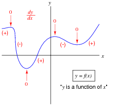
Define what "derivative" means when applied to the graph of a function. For instance, examine this graph:
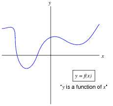
Label all the points where the derivative of the function ([dy/dx]) is positive, where it is negative, and where it is equal to zero.
Reveal Answer
The graphical interpretation of "derivative" means the
slope of the function at any given point.
Notes:
Usually students find the concept of the derivative easiest to understand in graphical form: being the slope of the graph. This is true whether or not the independent variable is time (an important point given that most ïntuitive" examples of the derivative are time-based!).
Hide Answer
Question 25:
Shown here is the graph for the function y = x
2:
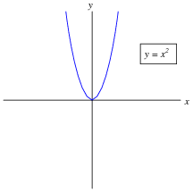
Sketch an approximate plot for the
derivative of this function.
Reveal Answer
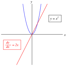
Challenge question: derivatives of power functions are easy to determine if you know the procedure. In this case, the derivative of the function y = x
2 is [dy/dx] = 2x. Examine the following functions and their derivatives to see if you can recognize the "rule" we follow:
-
�
-
y = x3 [dy/dx] = 3x2
-
�
- y = x4 [dy/dx] = 4x3
-
�
- y = 2x4 [dy/dx] = 8x3
-
�
- y = 10x5 [dy/dx] = 50x4
-
�
- y = 2x3 + 5x2 - 7x [dy/dx] = 6x2 + 10x - 7
-
�
- y = 5x3 - 2x - 16 [dy/dx] = 15x2 - 2
-
�
- y = 4x7 - 6x3 + 9x + 1 [dy/dx] = 28x6 - 18x2 + 9
Notes:
Usually students find the concept of the derivative easiest to understand in graphical form: being the slope of the graph. This is true whether or not the independent variable is time (an important point given that most ïntuitive" examples of the derivative are time-based!).
Even if your students are not yet familiar with the power rule for calculating derivatives, they should be able to tell that [dy/dx] is zero when x = 0, positive when x > 0, and negative when x < 0.
Hide Answer
Question 26:
Calculus is widely (and falsely!) believed to be too complicated for the average person to understand. Yet, anyone who has ever driven a car has an intuitive grasp of calculus' most basic concepts:
differentiation and
integration. These two complementary operations may be seen at work on the instrument panel of every automobile:
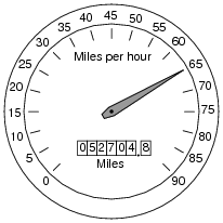
On this one instrument, two measurements are given: speed in miles per hour, and distance traveled in miles. In areas where metric units are used, the units would be kilometers per hour and kilometers, respectively. Regardless of units, the two variables of speed and distance are related to each other over time by the calculus operations of integration and differentiation. My question for you is which operation goes which way?
We know that speed is the rate of change of distance over time. This much is apparent simply by examining the units (miles
per hour indicates a rate of change over time). Of these two variables, speed and distance, which is the
derivative of the other, and which is the
integral of the other? Also, determine what happens to the value of each one as the other maintains a constant (non-zero) value.
Reveal Answer
Speed is the derivative of distance; distance is the integral of speed.
If the speed holds steady at some non-zero value, the distance will accumulate at a steady rate. If the distance holds steady, the speed indication will be zero because the car is at rest.
Notes:
The goal of this question is to get students thinking in terms of derivative and integral every time they look at their car's speedometer/odometer, and ultimately to grasp the nature of these two calculus operations in terms they are already familiar with.
Hide Answer
Question 27:
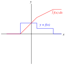
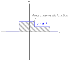
Define what ïntegral" means when applied to the graph of a function. For instance, examine this graph:
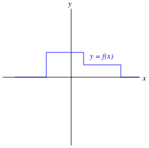
Sketch an approximate plot for the integral of this function.
Reveal Answer
The graphical interpretation of ïntegral" means the
area accumulated underneath the function for a given domain.
Notes:
Usually students find the concept of the integral a bit harder to grasp than the concept of the derivative, even when interpreted in graphical form. One way to help them make this "leap" is to remind them that integration and differentiation are inverse functions, then ask them to analyze the answer "backwards" (looking at the red integral plot and seeing how the blue function is the derivative of the red function). The thought process is analogous to explaining logarithms to students for the very first time: when we take the logarithm of a number, we are figuring out what power we would have to raise the base to get that number (e.g. log1000 = 3 ; 103 = 1000). When we determine the integral of a function, we are figuring out what other function, when differentiated, would result in the given function. This is the essence of what we mean by inverse functions, and it is an important concept in algebra, trigonometry, and calculus alike.
Hide Answer
Question 28:
A forward-biased PN semiconductor junction does not possess a "resistance" in the same manner as a resistor or a length of wire. Any attempt at applying Ohm's Law to a diode, then, is doomed from the start.
This is not to say that we cannot assign a
dynamic value of resistance to a PN junction, though. The fundamental definition of resistance comes from Ohm's Law, and it is expressed in derivative form as such:
The fundamental equation relating current and voltage together for a PN junction is Shockley's diode equation:
At room temperature (approximately 21 degrees C, or 294 degrees K), the thermal voltage of a PN junction is about 25 millivolts. Substituting 1 for the nonideality coefficient, we may simply the diode equation as such:
|
I = IS (e[V/0.025] - 1) or I = IS (e40 V - 1)
|
|
Differentiate this equation with respect to V, so as to determine [dI/dV], and then reciprocate to find a mathematical definition for dynamic resistance ([dV/dI]) of a PN junction. Hints: saturation current (I
S) is a very small constant for most diodes, and the final equation should express dynamic resistance in terms of thermal voltage (25 mV) and diode current (I).
Reveal Answer
Notes:
The result of this derivation is important in the analysis of certain transistor amplifiers, where the dynamic resistance of the base-emitter PN junction is significant to bias and gain approximations. I show the solution steps for you here because it is a neat application of differentiation (and substitution) to solve a real-world problem:
Now, we manipulate the original equation to obtain a definition for I
S e
40 V in terms of current, for the sake of substitution:
Substituting this expression into the derivative:
Reciprocating to get voltage over current (the proper form for resistance):
Now we may get rid of the saturation current term, because it is negligibly small:
The constant of 25 millivolts is not set in stone, by any means. Its value varies with temperature, and is sometimes given as 26 millivolts or even 30 millivolts.
Hide Answer
Question 29:
Just as addition is the inverse operation of subtraction, and multiplication is the inverse operation of division, a calculus concept known as
integration is the inverse function of differentiation. Symbolically, integration is represented by a long "S"-shaped symbol called the integrand:
|
If x =
|
dy
dt
|
( x is the derivative of y with respect to t) |
|
|
Then y =
|
�
�
|
x dt ( y is the integral of x with respect to t) |
|
To be truthful, there is a bit more to this reciprocal relationship than what is shown above
f, but the basic idea you need to grasp is that integration ün-does" differentiation, and visa-versa. Derivatives are a bit easier for most people to understand, so these are generally presented before integrals in calculus courses. One common application of derivatives is in the relationship between position, velocity, and acceleration of a moving object. Velocity is nothing more than rate-of-change of position over time, and acceleration is nothing more than rate-of-change of velocity over time:
|
v =
|
dx
dt
|
Velocity (v ) is the time-derivative of position (x ) |
|
|
a =
|
dv
dt
|
Acceleration (a ) is the time-derivative of velocity (v ) |
|
Illustrating this in such a way that shows differentiation as a process:
Given that you know integration is the inverse-function of differentiation, show how position, velocity, and acceleration are related by integration. Show this both in symbolic (proper mathematical) form as well as in an illustration similar to that shown above.
Footnotes:
f It is perfectly accurate to say that differentiation undoes integration, so that [d/dt]
�x dt = x, but to say that integration undoes differentiation is not entirely true because indefinite integration always leaves a constant C that may very well be non-zero, so that
�[dx/dt] dt = x + C rather than simply being x.
Reveal Answer
|
x =
|
�
�
|
v dt Position (x ) is the time-integral of velocity (v ) |
|
|
v =
|
�
�
|
a dt Velocity (v ) is the time-integral of acceleration (a ) |
|

Challenge question: explain why the following equations are more accurate than those shown in the answer.
|
x =
|
�
�
|
v dt + x0 Position (x ) is the time-integral of velocity (v ) |
|
|
v =
|
�
�
|
a dt + v0 Velocity (v ) is the time-integral of acceleration (a ) |
|
Where,
x
0 is the initial position (at time = 0)
v
0 is the initial velocity (at time = 0)
Notes:
The purpose of this question is to introduce the integral as an inverse-operation to the derivative. Introducing the integral in this manner (rather than in its historical origin as an accumulation of parts) builds on what students already know about derivatives, and prepares them to see integrator circuits as counterparts to differentiator circuits rather than as unrelated entities.
Hide Answer
Question 30:
Calculus is a branch of mathematics that originated with scientific questions concerning
rates of change. The easiest rates of change for most people to understand are those dealing with time. For example, a student watching their savings account dwindle over time as they pay for tuition and other expenses is very concerned with rates of change (
dollars per day being spent).
The "derivative" is how rates of change are symbolically expressed in mathematical equations. For example, if the variable S represents the amount of money in the student's savings account and t represents time, the rate of change of dollars over time (the
time-derivative of the student's account balance) would be written as [dS/dt]. The process of calculating this rate of change from a record of the account balance over time, or from an equation describing the balance over time, is called
differentiation.
Suppose, though, that instead of the bank providing the student with a statement every month showing the account balance on different dates, the bank were to provide the student with a statement every month showing the
rates of change of the balance over time, in dollars per day, calculated at the end of each day:
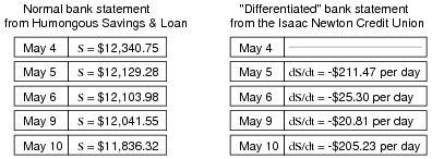
Explain how the Isaac Newton Credit Union calculates the derivative ([dS/dt]) from the regular account balance numbers (S in the Humongous Savings & Loan statement), and then explain how the student who banks at Isaac Newton Credit Union could figure out how much money is in their account at any given time.
Hint: the process of calculating a variable's value from rates of change is called
integration in calculus. It is the opposite (inverse) function of differentiation.
Reveal Answer
The Isaac Newton Credit Union differentiates S by dividing the difference between consecutive balances by the number of days between those balance figures. Differentiation is fundamentally a process of division.
To integrate the [dS/dt] values shown on the Credit Union's statement so as to arrive at values for S, we must either repeatedly add or subtract the days' rate-of-change figures, beginning with a starting balance. Thus, integration is fundamentally a process of multiplication.
Follow-up question: explain why a starting balance is absolutely necessary for the student banking at Isaac Newton Credit Union to know in order for them to determine their account balance at any time. Why would it be impossible for them to figure out how much money was in their account if the only information they possessed was the [dS/dt] figures?
Notes:
The purpose of this question is to introduce the concept of the integral to students in a way that is familiar to them. Hopefully the opening scenario of a dwindling savings account is something they can relate to!
Some students may ask why the differential notation [dS/dt] is used rather than the difference notation [(DS)/(Dt)] in this example, since the rates of change are always calculated by subtraction of two data points (thus implying a D). Given that the function here is piecewise and not continuous, one could argue that it is not differentiable at the points of interest. My purpose in using differential notation is to familiarize students with the concept of the derivative in the context of something they can easily relate to, even if the particular details of the application suggest a more correct notation.
Hide Answer