Capacitors
Question 1:
Identify some of the different types of capacitors, and their characteristics.
Notes:
There is much to be researched on different capacitor types and characteristics! Encourage your students to research both textbooks and capacitor manufacturer literature for more information.
Question 2:
How are electrolytic capacitors constructed, and what is particularly noteworthy about their use?
Follow-up question: identify the schematic symbol for any type of polarized capacitor, electrolytics included.
Notes:
There are many features of electrolytic capacitors unique to that type, not the least of which being their means of manufacture. Since these capacitors are used so often for low-voltage electronic applications, it is well worth the students' time to study them well and know their idiosyncrasies.
Question 3:
A capacitor has a label on it saying, "100 WVDC". What does this label mean? What is the consequence of exceeding this rating?
Notes:
As with resistors and resistance ratings, there is more to the rating of a capacitor than merely capacitance! Discuss with your students the importance of safety when working with capacitors, not only from shock hazard but also from explosions (resulting from excessive voltage).
Question 4:
Capacitors may pose an electric shock hazard, even in unpowered circuits. Explain why.
Notes:
An interesting follow-up question to pose would be: how do we safely discharge a capacitor charged with dangerous levels of voltage?
Question 5:
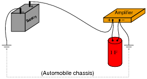
Very large capacitors (typically in excess of 1 Farad!) are often used in the DC power wiring of high-power audio amplifier systems installed in automobiles. The capacitors are connected in parallel with the amplifier's DC power terminals, as close to the amplifier as possible, like this:
|
|
What is the purpose of having a capacitor connected in parallel with the amplifier's power terminals? What benefit does this give to the audio system, overall?
Incidentally, this same technique is used in computer circuitry to stabilize the power supply voltage powering digital logic circuits, which draw current from the supply in rapid ßurges" as they switch between their ön" and öff" states. In this application, the capacitors are known as decoupling capacitors.
Notes:
Audio system engineering usually inspires interest among music-loving students, especially young students who crave maximum audio power in their automobiles' sound systems! This question is designed to provoke interest as much as it is intended to explore capacitor function.
With regard to "decoupling" capacitors, your students will likely have to use capacitors in this manner when they progress to building semiconductor circuits. If you have a printed circuit board from a computer (a "motherboard") available to show your students, it would be a good example of decoupling capacitors in use.
Question 6:
A 10 mF capacitor is charged to a voltage of 20 volts. How many coulombs of electric charge are stored in this capacitor?
Notes:
Don't give your students the equation with which to perform this calculation! Let them find it on their own.
Question 7:
A 470 mF capacitor is subjected to an applied voltage that changes at a rate of 200 volts per second. How much current will there be "through" this capacitor?
Explain why I placed quotation marks around the word "through" in the previous sentence. Why can't this word be used in its fullest sense when describing electric current in a capacitor circuit?
Notes:
Don't give your students the equation with which to perform this calculation! Let them find it on their own. The [dv/dt] notation may be foreign to students lacking a strong mathematical background, but don't let this be an obstacle to learning! Rather, use this as a way to introduce those students to the concept of rates of change, and to the calculus concept of the derivative.
Question 8:
Two 470 mF capacitors connected in series are subjected to a total applied voltage that changes at a rate of 200 volts per second. How much current will there be "through" these capacitors? Hint: the total voltage is divided evenly between the two capacitors.
Now suppose that two 470 mF capacitors connected in parallel are subjected to the same total applied voltage (changing at a rate of 200 volts per second). How much total current will there be "through" these capacitors?
Follow-up question: what do these figures indicate about the nature of series-connected and parallel connected capacitors? In other words, what single capacitor value is equivalent to two series-connected 470 mF capacitors, and what single capacitor value is equivalent to two parallel-connected 470 mF capacitors?
Notes:
If your students are having difficulty answering the follow-up question in the Answer, ask them to compare these current figures (47 mA and 188 mA) against the current that would go through just one of the 470 mF capacitors under the same condition (an applied voltage changing at a rate of 200 volts per second).
It is, of course, important that students know how series-connected and parallel connected capacitors behave. However, this is typically a process of rote memorization for students rather than true understanding. With this question, the goal is to have students come to a realization of capacitor connections based on their understanding of series and parallel voltages and currents.
Question 9:
Suppose two 33 mF capacitors are connected in series with each other. What will their combined capacitance be, in Farads? Explain your answer.
Notes:
Capacitors often confuse new students of electronics because their values do not add up the same as resistors. It is important in answering this question that your students understand why series capacitances combine as they do. There is more than one way to explain this phenomenon - explain in terms of capacitor dimensions, or in terms of voltage drop and charge storage.
Question 10:
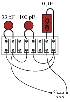
Calculate the total capacitance in this collection of capacitors, as measured between the two wires:
|
|
Follow-up question: suppose one of the terminal block's hold-down screws were to come loose on one of the leads for the middle capacitor, making a bad (open) connection. What effect would this have on the total capacitance?
Notes:
It is most helpful to first draw a schematic diagram for this capacitor network before trying to perform any capacitance calculations, in order that a clear understanding of the series/parallel connections be established.
Question 11:
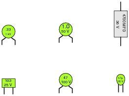
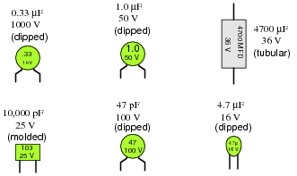
Identify the following capacitor values and styles:
|
|
|
|
Notes:
Ask your students how they can tell whether a capacitor's value is given in microfarads or picofarads. There is a way, even if the metric prefix is not printed on the capacitor!
Question 12:
When checked with an ohmmeter, how should a properly functioning capacitor respond?
Follow-up question: what do you suppose is the most likely failure "mode" of a capacitor, open or shorted? Explain your answer.
Notes:
Have your students actually test a few capacitors with their ohmmeters in class. For large capacitor values, the charging time may be substantial! Students need to be aware of this, and the effect it has on the ohmmeter's indication.
Although an ohmmeter check of a capacitor is not a comprehensive analysis, it is certainly better than nothing, and will detect the more common faults.
Question 13:
Find one or two real capacitors and bring them with you to class for discussion. Identify as much information as you can about your capacitors prior to discussion:
- �
- Capacitance (ideal)
- �
- Capacitance (actual)
- �
- Voltage rating
- �
- Type (mica, mylar, electrolytic, etc.)
Be prepared to prove the actual capacitance of your capacitors in class, by using a multimeter (assuming your multimeter is capable of measuring capacitance)!
Notes:
The purpose of this question is to get students to kinesthetically interact with the subject matter. It may seem silly to have students engage in a ßhow and tell" exercise, but I have found that activities such as this greatly help some students. For those learners who are kinesthetic in nature, it is a great help to actually touch real components while they're learning about their function. Of course, this question also provides an excellent opportunity for them to practice interpreting component markings, use a multimeter, access datasheets, etc.
Question 14:
An important parameter in capacitor performance is ESR. Define ESR, and explain what causes it.
Notes:
Discuss with your students why ESR matters, especially in decoupling applications where capacitors are expected to handle large [dv/dt] transients.
Question 15:
Capacitors often have letter codes following the three-digit number codes. For example, here are some typical capacitor codes, complete with letters:
- �
- 473K
- �
- 102J
- �
- 224M
- �
- 331F
Determine the meaning of letters used on capacitor labels, what the respective numeric values are for all the available letters, and then finally what these four specific number/letter codes mean (shown above).
Notes:
The capacitor tolerance codes are easy enough for students to research on their own. For your own reference, though:
- �
- D = � 0.5%
- �
- F = � 1%
- �
- G = � 2%
- �
- H = � 3%
- �
- J = � 5%
- �
- K = � 10%
- �
- M = � 20%
- �
- P = +100%, -0%
- �
- Z = +80%, -20%
Same for the four capacitor labels given in the question:
- �
- 473K = 47 nF � 10%
- �
- 102J = 1 nF � 5%
- �
- 224M = 0.22 mF � 20%
- �
- 331F = 330 pF � 1%