Elementary circuits
Question 1:
In the simplest terms you can think of, define what an electrical circuit is.
Notes:
Although definitions are easy enough to research and repeat, it is important that students learn to cast these concepts into their own words. Asking students to give practical examples of "circuits" and "non-circuits" is one way to ensure deeper investigation of the concepts than mere term memorization.
The word "circuit," in vernacular usage, often refers to anything electrical. Of course, this is not true in the technical sense of the term. Students will come to realize that many terms they learn and use in an electricity or electronics course are actually mis-used in common speech. The word ßhort" is another example: technically it refers to a specific type of circuit fault. Commonly, though, people use it to refer to any type of electrical problem.
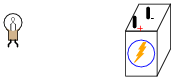
Question 2:
Given a battery and a light bulb, show how you would connect these two devices together with wire so as to energize the light bulb:
|
|
|
|
Notes:
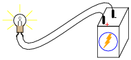
This question gives students a good opportunity to discuss the basic concept of a circuit. It is very easy to build, safe, and should be assembled by each student individually in class. Also, emphasize how simple circuits like this may be assembled at home as part of the "research" portion of the worksheet. To research answers for worksheet questions does not necessarily mean the information has to come from a book! Encourage experimentation when the conditions are known to be safe.
Have students brainstorm all the important concepts learned in making this simple circuit. What general principles may be derived from this particular exercise?
Question 3:
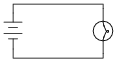
Draw an electrical schematic diagram of a circuit where a battery provides electrical energy to a light bulb.
|
|
Other orientations of the components within the diagram are permissible. What matters, though, is for there to be a single, continuous path for electric current from the battery, to the light bulb, and back to the other terminal of the battery.
Notes:
Impress upon the students the importance of learning to "communicate" in the language of schematic diagrams. The symbols and conventions learned here are international, and not limited to use in the United States.
Question 4:
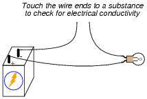
How could a battery, a light bulb, and some lengths of metal wire be used as a conductivity tester, to test the ability of different objects to conduct electricity?
|
|
Notes:
Not only is this question an opportunity to solve a problem, but it lends itself well to simple and safe experimentation. Encourage students to build their own conductivity testers and test various substances with them.
Question 5:
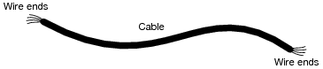
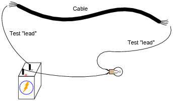
Suppose we had a long length of electrical cable (flexible tubing containing multiple wires) that we suspected had some broken wires in it. Design a simple testing circuit that could be used to check each of the cable's wires individually.
|
|
|
|
Notes:
A significant portion of electrical/electronic circuit problems are caused by nothing more complex than broken wire connections, or faults along the length of wires. Testing cables for wire breaks is a very practical exercise.
The same technique may be used to "map" wires from one end of a cable to the other, in the event that the wires are not color-coded or otherwise made identifiable.
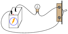
Question 6:
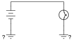
What do the symbols with the question marks next to them refer to? In the circuit shown, would the light bulb be energized?
|
|
Notes:
Ask the students about the relative conductivities of metal chassis versus dirt (earth ground). Is a current pathway formed by two metal chassis grounds equivalent to a current pathway formed by two earth grounds? Why or why not? What conditions may affect these relative conductivities?
Question 7:
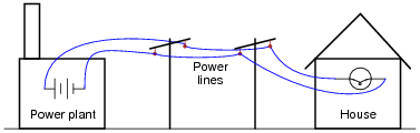
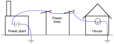
Shown here is a simplified representation of an electrical power plant and a house, with the source of electricity shown as a battery, and the only electrical "load" in the house being a single light bulb:
|
|
Why would anyone use two wires to conduct electricity from a power plant to a house, as shown, when they could simply use one wire and a pair of ground connections, like this?
|
|
Notes:
Discuss the fact that although the earth (dirt) is a poor conductor of electricity, it may still be able to conduct levels of current lethal to the human body! The amount of current necessary to light up a household light bulb is typically far in excess of values lethal for the human body.
Question 8:
What, exactly, is a short circuit? What does it mean if a circuit becomes shorted? How does this differ from an open circuit?
Conversely, an open circuit is one where there is a break preventing any current from going through at all.
Notes:
Discuss with your students some of the potential hazards of short circuits. It will then be apparent why a ßhort circuit" is a bad thing. Ask students if they can think of any realistic circumstance that could lead to a short-circuit developing.
I have noticed over several years of teaching electronics that the terms ßhort" or ßhort-circuit" are often used by new students as generic labels for any type of circuit fault, rather than the specific condition just described. This is a habit that must be corrected, if students are to communicate intelligently with others in the profession. To say that a component ïs shorted" means a very definite thing: it is not a generic term for any type of circuit fault.
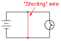
Question 9:
What would have to happen in this circuit for it to become shorted? In other words, determine how to make a short circuit using the components shown here:

|
|
|
|
Notes:
In real life, of course, short circuits are usually things to be avoided. Discuss with your students why short circuits are generally undesirable, and what role wire insulation plays in preventing them.
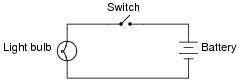
Question 10:
Examine this schematic diagram:
|
|
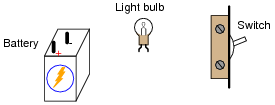
Now, without moving the following components, show how they may be connected together with wires to form the same circuit depicted in the schematic diagram above:
|
|
|
|
Follow-up question: suppose the circuit were built like this but the light bulb did not turn on when the switch was closed. Identify at least five specific things that could be wrong with the circuit to cause the light not to turn on when it should.
Notes:
One of the more difficult skills for students to develop is the ability to translate a nice, neat schematic diagram into a messy, real-world circuit, and visa-versa. Developing this skill requires lots of practice.
In case students have not learned battery symbol convention yet, please point out to them the "+" and "-" polarity marks, and note which side of the battery is which.
One analogy to use for the switch's function that makes sense with the schematic is a drawbridge: when the bridge is down (closed), cars may cross; when the bridge is up (open), cars cannot.
Question 11:
|
|
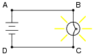
This circuit has four "test points" labeled with the letters A, B, C, and D. Assuming the circuit is functioning (light bulb is energized), determine whether or not there will be substantial voltage between the following sets of points:
- �
- Between A and B: voltage or no voltage?
- �
- Between B and C: voltage or no voltage?
- �
- Between C and D: voltage or no voltage?
- �
- Between D and A: voltage or no voltage?
- �
- Between A and C: voltage or no voltage?
- �
- Between D and B: voltage or no voltage?
Based on these voltage determinations, what general statement(s) can you make about the presence or absence of voltage in a functioning circuit?
- �
- Measuring between two terminals of a voltage source, or between two terminals of an energized load (a component having substantial resistance, with current going through it), there will be a voltage.
- �
- Measuring between two points that are electrically common to each other, there will be no voltage (or at least an insignificant amount of voltage).
Notes:
Electrically common points are defined as points within a circuit that are connected together by conductors of negligible resistance.
The concept of ëlectrically common" points is one that I have found very helpful in the analysis of circuits, because there are a some simple rules regarding voltage that relate to whether or not points in a circuit are "common" to each other.
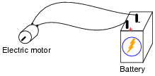
Question 12:
In this electrical circuit, trace the direction of current through the wires:
|
|
Notes:
This question breaches one of the more contentious subjects in electricity/electronics: which way do we denote the direction of current? While there is no debate as to which direction electrons move through a metal conductor carrying current, there are two different conventions for denoting current travel, one of which goes in the direction of electrons and the other which goes against the direction of electrons. The reason for having these two disparate conventions is embedded in the history of electrical science, and what your students find in their research will likely fuel an interesting conversation.