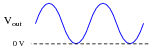
Clipper and clamper circuits
Question 1:
| Don't just sit there! Build something!! |
Learning to mathematically analyze circuits requires much study and practice. Typically, students practice by working through lots of sample problems and checking their answers against those provided by the textbook or the instructor. While this is good, there is a much better way.
You will learn much more by actually building and analyzing real circuits, letting your test equipment provide the änswers" instead of a book or another person. For successful circuit-building exercises, follow these steps:
- 1.
- Carefully measure and record all component values prior to circuit construction, choosing resistor values high enough to make damage to any active components unlikely.
- 2.
- Draw the schematic diagram for the circuit to be analyzed.
- 3.
- Carefully build this circuit on a breadboard or other convenient medium.
- 4.
- Check the accuracy of the circuit's construction, following each wire to each connection point, and verifying these elements one-by-one on the diagram.
- 5.
- Mathematically analyze the circuit, solving for all voltage and current values.
- 6.
- Carefully measure all voltages and currents, to verify the accuracy of your analysis.
- 7.
- If there are any substantial errors (greater than a few percent), carefully check your circuit's construction against the diagram, then carefully re-calculate the values and re-measure.
When students are first learning about semiconductor devices, and are most likely to damage them by making improper connections in their circuits, I recommend they experiment with large, high-wattage components (1N4001 rectifying diodes, TO-220 or TO-3 case power transistors, etc.), and using dry-cell battery power sources rather than a benchtop power supply. This decreases the likelihood of component damage.
As usual, avoid very high and very low resistor values, to avoid measurement errors caused by meter "loading" (on the high end) and to avoid transistor burnout (on the low end). I recommend resistors between 1 kW and 100 kW.
One way you can save time and reduce the possibility of error is to begin with a very simple circuit and incrementally add components to increase its complexity after each analysis, rather than building a whole new circuit for each practice problem. Another time-saving technique is to re-use the same components in a variety of different circuit configurations. This way, you won't have to measure any component's value more than once.
Notes:
It has been my experience that students require much practice with circuit analysis to become proficient. To this end, instructors usually provide their students with lots of practice problems to work through, and provide answers for students to check their work against. While this approach makes students proficient in circuit theory, it fails to fully educate them.
Students don't just need mathematical practice. They also need real, hands-on practice building circuits and using test equipment. So, I suggest the following alternative approach: students should build their own "practice problems" with real components, and try to mathematically predict the various voltage and current values. This way, the mathematical theory "comes alive," and students gain practical proficiency they wouldn't gain merely by solving equations.
Another reason for following this method of practice is to teach students scientific method: the process of testing a hypothesis (in this case, mathematical predictions) by performing a real experiment. Students will also develop real troubleshooting skills as they occasionally make circuit construction errors.
Spend a few moments of time with your class to review some of the "rules" for building circuits before they begin. Discuss these issues with your students in the same Socratic manner you would normally discuss the worksheet questions, rather than simply telling them what they should and should not do. I never cease to be amazed at how poorly students grasp instructions when presented in a typical lecture (instructor monologue) format!
A note to those instructors who may complain about the "wasted" time required to have students build real circuits instead of just mathematically analyzing theoretical circuits:
What is the purpose of students taking your course?
If your students will be working with real circuits, then they should learn on real circuits whenever possible. If your goal is to educate theoretical physicists, then stick with abstract analysis, by all means! But most of us plan for our students to do something in the real world with the education we give them. The "wasted" time spent building real circuits will pay huge dividends when it comes time for them to apply their knowledge to practical problems.
Furthermore, having students build their own practice problems teaches them how to perform primary research, thus empowering them to continue their electrical/electronics education autonomously.
In most sciences, realistic experiments are much more difficult and expensive to set up than electrical circuits. Nuclear physics, biology, geology, and chemistry professors would just love to be able to have their students apply advanced mathematics to real experiments posing no safety hazard and costing less than a textbook. They can't, but you can. Exploit the convenience inherent to your science, and get those students of yours practicing their math on lots of real circuits!
Question 2:
What type of electronic component do these symbols represent, and what special function does it perform?

|
|
Follow-up question: plot an approximate graph of current versus voltage for a varistor, and comment on how this compares to the current/voltage characteristic of a normal resistor.
Notes:
Ask your students to reveal their information sources used when researching varistors, and also if they were able to determine how these devices are constructed.
Question 3:
Explain how a surge protector functions: the kind of device used to protect electronic equipment against common power line voltage transients. Draw a schematic diagram to accompany your explanation.
Notes:
Ask students how a surge protector (or surge ßuppressor") is similar in principle to clipper circuits used for small electronic signals.
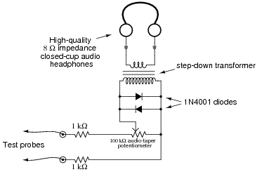
Question 4:
A technician builds her own audio test set for use in troubleshooting audio electronic circuitry. The test set is essentially a sensitive detector, allowing low-power audio signals to be heard:
|
|
What purpose do the two diodes serve in this circuit? Hint: if you remove the diodes from the circuit, you will not be able to hear the difference in most cases!
Review question: the purpose of the transformer is to increase the effective impedance of the headphones, from 8 W to a much larger value. Calculate this larger value, given a transformer turns ratio of 22:1.
Notes:
My first encounter with this application of diodes came when I was quite young, soldering together a kit multimeter. I was very confused why the meter movement had two diodes connected to it in parallel like this. All I knew about diodes at the time was that they acted as one-way valves for electricity. I did not understand that they had a substantial forward voltage drop, which is the key to understanding how they work in applications such as this. While this may seem to be a rather unorthodox use of diodes, it is actually rather common.
Incidentally, I highly recommend that students build such an audio test set for their own experimental purposes. Even with no amplifier, this instrument is amazingly sensitive. An inexpensive 120 volt/6 volt step-down power transformer works well as an impedance-matching transformer, and is insulated enough to provide a good margin of safety (electrical isolation) for most applications. An old microwave over power transformer works even better (when used in a step-down configuration), giving several thousand volts worth of isolation between primary and secondary windings.
The circuit even works to detect DC signals and AC signals with frequencies beyond the audio range. By making and breaking contact with the test probe(s), ßcratching" sounds will be produced if a signal of sufficient magnitude is present. With my cheap "Radio Shack" closed-cup headphones, I am able to reliably detect DC currents of less than 0.1 mA with my detector! Your mileage may vary, depending on how good your hearing is, and how sensitive your headphones are.
I have used my own audio detector many times in lieu of an oscilloscope to detect distortion in audio circuits (very rough assessments, mind you, not precision at all) and even as a detector of DC voltage (detecting the photovoltaic output voltage of a regular LED). It may be used as a sensitive "null" instrument in both AC and DC bridge circuits (again, DC detection requires you to make and break contact with the circuit, listening for "clicking" or ßcratching" sounds in the headphones).
Another fun thing to do with this detector is connect it to an open coil of wire and "listen" for AC magnetic fields. Place such a coil near a working computer hard drive, and you can hear the read/write head servos in action!
If it isn't clear to you already, I am very enthusiastic about the potential of this circuit for student engagement and learning . . .
Question 5:
Predict how the operation of this sensitive audio detector circuit will be affected as a result of the following faults. Consider each fault independently (i.e. one at a time, no multiple faults):
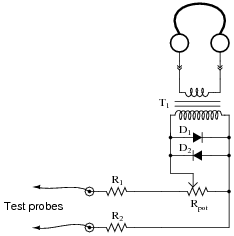
|
|
- �
- Diode D1 fails open:
- �
- Diode D1 fails shorted:
- �
- Transformer T1 primary winding fails open:
- �
- Resistor R1 fails open:
- �
- Solder bridge (short) past resistor R1:
- �
- Wiper fails to contact slide in potentiometer:
For each of these conditions, explain why the resulting effects will occur.
- �
- Diode D1 fails open: No effect on small signals, clipping of large signals will be incomplete (only one-half of the waveform will be clipped in amplitude).
- �
- Diode D1 fails shorted: No sound heard at headphones at all.
- �
- Transformer T1 primary winding fails open: No sound heard at headphones at all.
- �
- Resistor R1 fails open: No sound heard at headphones at all.
- �
- Solder bridge (short) past resistor R1: Volume (slightly) louder than usual.
- �
- Wiper fails to contact slide in potentiometer: No sound heard at headphones at all.
Notes:
The purpose of this question is to approach the domain of circuit troubleshooting from a perspective of knowing what the fault is, rather than only knowing what the symptoms are. Although this is not necessarily a realistic perspective, it helps students build the foundational knowledge necessary to diagnose a faulted circuit from empirical data. Questions such as this should be followed (eventually) by other questions asking students to identify likely faults based on measurements.
Question 6:
Determine both the waveshape and amplitude of the AC signal measured by the oscilloscope at the output of this circuit:
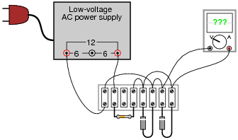
|
|
The diodes are model 1N4001, each. The resistor's color code is Brown, Black, Orange, Silver.
Notes:
Ask your students why the waveform will be square rather than sinusoidal. Is it a perfect square-wave? Why or why not?
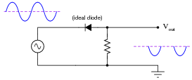
Question 7:
Sketch the shape of the output voltage waveform for this "clipper" circuit, assuming an ideal diode with no forward voltage drop:
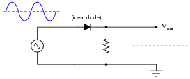
|
|
|
|
Notes:
This circuit is not difficult to analyze if you consider both half-cycles of the AC voltage source, one at a time. Ask your students to demonstrate this method of analysis, either individually or in groups, at the front of the classroom so everyone can see and understand.
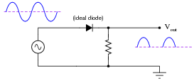
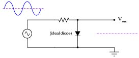
Question 8:
Sketch the shape of the output voltage waveform for this "clipper" circuit, assuming an ideal diode with no forward voltage drop:
|
|
|
|
Notes:
This circuit is not difficult to analyze if you consider both half-cycles of the AC voltage source, one at a time. Ask your students to demonstrate this method of analysis, either individually or in groups, at the front of the classroom so everyone can see and understand.
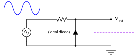
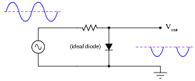
Question 9:
Sketch the shape of the output voltage waveform for this "clipper" circuit, assuming an ideal diode with no forward voltage drop:

|
|
|
|
Notes:
This circuit is not difficult to analyze if you consider both half-cycles of the AC voltage source, one at a time. Ask your students to demonstrate this method of analysis, either individually or in groups, at the front of the classroom so everyone can see and understand.
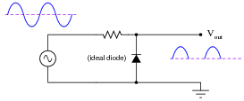
Question 10:
Sketch the shape of the output voltage waveform for this "clipper" circuit, assuming an ideal diode with no forward voltage drop:
|
|
|
|
Notes:
This circuit is not difficult to analyze if you consider both half-cycles of the AC voltage source, one at a time. Ask your students to demonstrate this method of analysis, either individually or in groups, at the front of the classroom so everyone can see and understand.
Question 11:
Predict how the operation of this clipper circuit will be affected as a result of the following faults. Consider each fault independently (i.e. one at a time, no multiple faults):
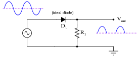
|
|
- �
- Diode D1 fails open:
- �
- Diode D1 fails shorted:
- �
- Resistor R1 fails open:
- �
- Resistor R1 fails shorted:
For each of these conditions, explain why the resulting effects will occur.
- �
- Diode D1 fails open: No output voltage at all.
- �
- Diode D1 fails shorted: Full AC signal at output (no clipping at all).
- �
- Resistor R1 fails open: No change (if diode is indeed ideal), but realistically there may not be much clipping if the receiving circuit has an extremely large input impedance.
- �
- Resistor R1 fails shorted: No output voltage at all.
Notes:
The purpose of this question is to approach the domain of circuit troubleshooting from a perspective of knowing what the fault is, rather than only knowing what the symptoms are. Although this is not necessarily a realistic perspective, it helps students build the foundational knowledge necessary to diagnose a faulted circuit from empirical data. Questions such as this should be followed (eventually) by other questions asking students to identify likely faults based on measurements.
Question 12:
Predict how the operation of this clipper circuit will be affected as a result of the following faults. Consider each fault independently (i.e. one at a time, no multiple faults):
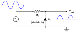
|
|
- �
- Diode D1 fails open:
- �
- Diode D1 fails shorted:
- �
- Resistor R1 fails open:
- �
- Resistor R1 fails shorted:
For each of these conditions, explain why the resulting effects will occur.
- �
- Diode D1 fails open: Full AC signal at output (no clipping at all).
- �
- Diode D1 fails shorted: No output voltage at all.
- �
- Resistor R1 fails open: No output voltage at all.
- �
- Resistor R1 fails shorted: Normal operation if source impedance is substantial, otherwise diode and/or source may be damaged by direct short every half-cycle.
Notes:
The purpose of this question is to approach the domain of circuit troubleshooting from a perspective of knowing what the fault is, rather than only knowing what the symptoms are. Although this is not necessarily a realistic perspective, it helps students build the foundational knowledge necessary to diagnose a faulted circuit from empirical data. Questions such as this should be followed (eventually) by other questions asking students to identify likely faults based on measurements.
Question 13:
Design a clipper circuit that eliminates the positive portion of this AC waveform, leaving only the negative half-cycles to appear on the output:
|
|
|
|
Note: the circuit shown here is not the only possible solution!
Follow-up question: the output waveform shown for this circuit is true only for an ideal diode, not a real diode. Explain what the output waveform would look like if a real diode were used, and recommend a diode model that closely approximates the ideal case for this application.
Notes:
A good review of basic diode concepts here. Students should recognize the output waveform as being indicative of half-wave rectification, which may cause them to think of other circuit designs.
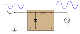
Question 14:
Design a clipper circuit that clips any portion of the input AC waveform below +4 volts:
|
|
|
|
Follow-up question: explain why a Schottky diode is shown in this circuit rather than a regular silicon PN-junction diode. What characteristic(s) of Schottky diodes make them well suited for many clipper applications?
Notes:
Ask your students whether they would classify this circuit as a series or a shunt clipper.
If your students are unfamiliar with Schottky diodes, this is an excellent opportunity to discuss them! Their low forward voltage drop and fast switching characteristics make them superior for most signal clipper and clamper circuits.
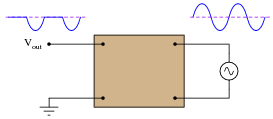
Question 15:
Describe what happens to the shape of the load voltage waveform when the potentiometer is adjusted in this clipper circuit:
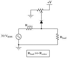
|
|
Follow-up question: modify this circuit to function as a variable negative peak clipper instead.
Notes:
Some students may ask what this mathematical statement means:
|
Explain to them that the "double-chevron" symbol means "much greater than" (reversing the chevrons would mean "much less than," of course).
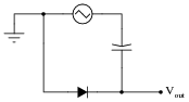
Question 16:
There is a problem with this clipper circuit, as evidenced by the output waveform:
|
|
What is the most likely cause of this problem, and how would you verify your conclusion with further measurements?
Notes:
Have your students figured out any other possibilities for the fault in this circuit? They do exist, and in fact may be more likely than a failed-open diode! Ask your students how and why they chose the answer they did, and be sure to have them explain their follow-up diagnostic procedures.
Question 17:
The simplest form of AM radio receiver is the so-called crystal receiver circuit. It gets its name from the very early days of solid-state electronics, when crude signal rectifying diodes were constructed from certain types of mineral crystals:
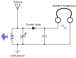
|
|
Explain how the AM radio signal becomes "demodulated" into an audio-frequency signal, through the clipping action of the diode.
Notes:
Ask your students to explain the purpose of each component in the "crystal" radio circuit, not just those components related to the clipping function.
Question 18:
Clamper circuits are sometimes referred to as DC restorer circuits. Explain why.
Does a "clamper" circuit change the shape of a voltage waveform, like a "clipper" circuit does? Explain why or why not.
Notes:
Ask your students to provide an example of a clamper circuit schematic.
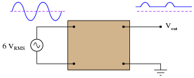
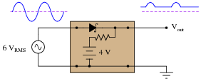
Question 19:
Draw the output waveform shape for this circuit, assuming an ideal diode (no forward voltage drop and no reverse leakage):
|
|
|
|
Follow-up question: how does the clamper circuit "know" how much it needs to bias the AC voltage waveform so that it gets shifted just enough to eliminate reversals of polarity? Would this circuit function the same if the AC voltage were increased or decreased? Explain why.
Notes:
Ask your students to replace the capacitor with a DC voltage source (oriented in the correct polarity, of course), and explain how the capacitor actually functions as a voltage bias in this clamper circuit.
Question 20:
Design a clamper circuit that biases the AC waveform so it lies completely below (negative) the zero line:
|
|
|
|
Notes:
Have multiple students share their thoughts as to how they designed the clamper circuit.
Question 21:
In this circuit, the values of capacitor C1 and resistor R1 are chosen to provide a short time constant, so they act as a differentiator network. This results in a brief pulse of voltage across R1 at each leading edge of the square wave input. Capacitor C2 and resistor R2 are sized to provide a long time constant, so as to form an integrator network. This time-averages the brief pulses into a final DC output voltage relatively free of ripple.
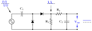
|
|
Explain what happens to the output voltage as the input frequency is increased, assuming the input voltage amplitude does not change. Can you think of any practical applications for a circuit such as this?
Notes:
Do not accept an answer from students along the lines of "frequency measurement." Ask them to provide some practical examples of systems where frequency measurement is important. If they have difficulty thinking of anything practical, suggest that the input (square wave) signal might come from a sensor detecting shaft rotation (one pulse per revolution), then ask them to think of possible applications for a circuit such as this.