Counters
Question 1:
| Don't just sit there! Build something!! |
Learning to analyze digital circuits requires much study and practice. Typically, students practice by working through lots of sample problems and checking their answers against those provided by the textbook or the instructor. While this is good, there is a much better way.
You will learn much more by actually building and analyzing real circuits, letting your test equipment provide the änswers" instead of a book or another person. For successful circuit-building exercises, follow these steps:
- 1.
- Draw the schematic diagram for the digital circuit to be analyzed.
- 2.
- Carefully build this circuit on a breadboard or other convenient medium.
- 3.
- Check the accuracy of the circuit's construction, following each wire to each connection point, and verifying these elements one-by-one on the diagram.
- 4.
- Analyze the circuit, determining all output logic states for given input conditions.
- 5.
- Carefully measure those logic states, to verify the accuracy of your analysis.
- 6.
- If there are any errors, carefully check your circuit's construction against the diagram, then carefully re-analyze the circuit and re-measure.
Always be sure that the power supply voltage levels are within specification for the logic circuits you plan to use. If TTL, the power supply must be a 5-volt regulated supply, adjusted to a value as close to 5.0 volts DC as possible.
One way you can save time and reduce the possibility of error is to begin with a very simple circuit and incrementally add components to increase its complexity after each analysis, rather than building a whole new circuit for each practice problem. Another time-saving technique is to re-use the same components in a variety of different circuit configurations. This way, you won't have to measure any component's value more than once.
Notes:
It has been my experience that students require much practice with circuit analysis to become proficient. To this end, instructors usually provide their students with lots of practice problems to work through, and provide answers for students to check their work against. While this approach makes students proficient in circuit theory, it fails to fully educate them.
Students don't just need mathematical practice. They also need real, hands-on practice building circuits and using test equipment. So, I suggest the following alternative approach: students should build their own "practice problems" with real components, and try to predict the various logic states. This way, the digital theory "comes alive," and students gain practical proficiency they wouldn't gain merely by solving Boolean equations or simplifying Karnaugh maps.
Another reason for following this method of practice is to teach students scientific method: the process of testing a hypothesis (in this case, logic state predictions) by performing a real experiment. Students will also develop real troubleshooting skills as they occasionally make circuit construction errors.
Spend a few moments of time with your class to review some of the "rules" for building circuits before they begin. Discuss these issues with your students in the same Socratic manner you would normally discuss the worksheet questions, rather than simply telling them what they should and should not do. I never cease to be amazed at how poorly students grasp instructions when presented in a typical lecture (instructor monologue) format!
I highly recommend CMOS logic circuitry for at-home experiments, where students may not have access to a 5-volt regulated power supply. Modern CMOS circuitry is far more rugged with regard to static discharge than the first CMOS circuits, so fears of students harming these devices by not having a "proper" laboratory set up at home are largely unfounded.
A note to those instructors who may complain about the "wasted" time required to have students build real circuits instead of just mathematically analyzing theoretical circuits:
What is the purpose of students taking your course?
If your students will be working with real circuits, then they should learn on real circuits whenever possible. If your goal is to educate theoretical physicists, then stick with abstract analysis, by all means! But most of us plan for our students to do something in the real world with the education we give them. The "wasted" time spent building real circuits will pay huge dividends when it comes time for them to apply their knowledge to practical problems.
Furthermore, having students build their own practice problems teaches them how to perform primary research, thus empowering them to continue their electrical/electronics education autonomously.
In most sciences, realistic experiments are much more difficult and expensive to set up than electrical circuits. Nuclear physics, biology, geology, and chemistry professors would just love to be able to have their students apply advanced mathematics to real experiments posing no safety hazard and costing less than a textbook. They can't, but you can. Exploit the convenience inherent to your science, and get those students of yours practicing their math on lots of real circuits!
Question 2:
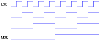
Count from zero to fifteen, in binary, keeping the bits lined up in vertical columns like this:
0000
0001
0010
. . .
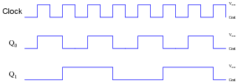
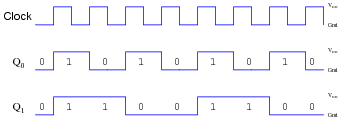
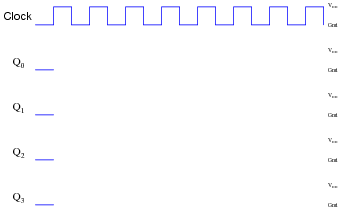
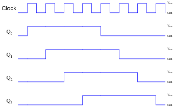
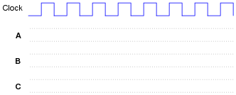
Now, reading from top to bottom, notice the alternating patterns of 0's and 1's in each place (i.e. one's place, two's place, four's place, eight's place) of the four-bit binary numbers. Note how the least significant bit alternates more rapidly than the most significant bit. Draw a timing diagram showing the respective bits as waveforms, alternating between "low" and "high" states, and comment on the frequency of each of the bits.
|
|
Notes:
The purpose of this question is to get students to relate the well-known binary counting sequence to electrical events: in this case, square-wave signals of different frequency.
Question 3:
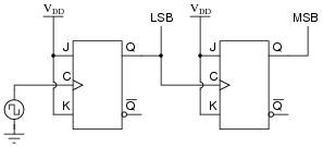
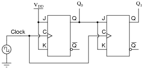
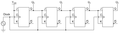
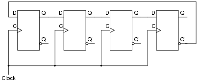
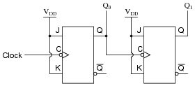
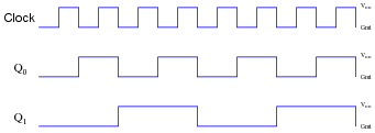
Shown here is a simple two-bit binary counter circuit:
|
|
The Q output of the first flip-flop constitutes the least significant bit (LSB), while the second flip-flop's Q output constitutes the most significant bit (MSB).
Based on a timing diagram analysis of this circuit, determine whether it counts in an up sequence (00, 01, 10, 11) or a down sequence (00, 11, 10, 01). Then, determine what would have to be altered to make it count in the other direction.
Notes:
Actually, the counting sequence may be determined simply by analyzing the flip-flops' actions after the first clock pulse. Writing a whole timing diagram for the count sequence may help some students to understand how the circuit works, but the more insightful students will be able to determine its counting direction without having to draw any timing diagram at all.
Question 4:
Counter circuits built by cascading the output of one flip-flop to the clock input of the next flip-flop are generally referred to as ripple counters. Explain why this is so. What happens in such a circuit that earns it the label of "ripple"? Is this effect potentially troublesome in circuit operation, or is it something of little or no consequence?
Whether or not this constitutes a problem in a digital circuit depends on the circuit's tolerance of false counts. In many circuits, there are ways to avoid this problem without resorting to a re-design of the counter.
Notes:
If your students have studied binary adder circuits, they should recognize the term "ripple" in a slightly different context. Different circuit, same problem.
Question 5:
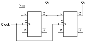
A style of counter circuit that completely circumvents the "ripple" effect is called the synchronous counter:
|
|
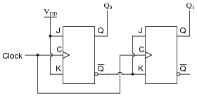
Complete a timing diagram for this circuit, and explain why this design of counter does not exhibit "ripple" on its output lines:
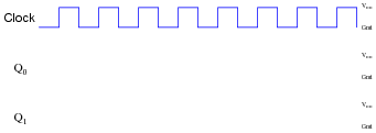
|
|
Challenge question: to really understand this type of counter circuit well, include propagation delays in your timing diagram.
|
|
However, even with propagation delays included (equal delays for each flip-flop), you should find there is still no "ripple" effect in the output count.
Notes:
"Walk" through the timing diagram given in the answer, and have students explain how the logic states correspond to a two-bit binary counting sequence.
Question 6:
A student just learned how a two-bit synchronous binary counter works, and he is excited about building his own. He does so, and the circuit works perfectly.
|
|
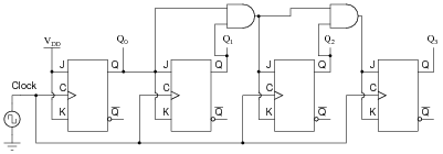
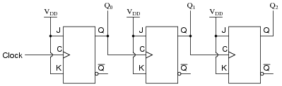
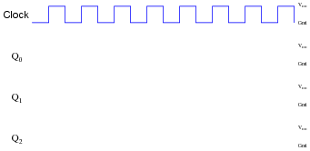
After that success, student tries to expand on their success by adding more flip-flops, following the same pattern as the two original flip-flops:

|
|
Unfortunately, this circuit didn't work. The sequence it generates is not a binary count. Determine what the counting sequence of this circuit is, and then try to figure out what modifications would be required to make it count in a proper binary sequence.
|
|
Notes:
I like to introduce students to synchronous counter circuitry by first having them examine a circuit that doesn't work. After seeing a two-bit synchronous counter circuit, it makes intuitive sense to most people that the same cascaded flip-flop strategy should work for synchronous counters with more bits, but it doesn't. When students understand why the simple scheme doesn't work, they are prepared to understand why the correct scheme does.
Question 7:
Complete a timing diagram for this synchronous counter circuit, and identify the direction of its binary count:
|
|

|
|
|
|
Notes:
Discuss with your students how to relate timing diagrams to binary counts (as shown in the answer).
Question 8:
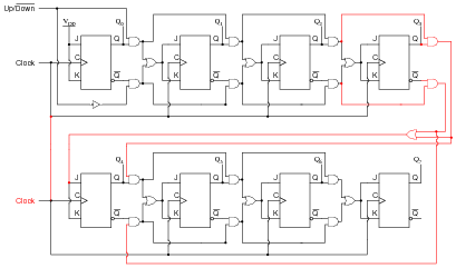
Synchronous counter circuits tend to confuse students. The circuit shown here is the design that most students think ought to work, but actually doesn't:
|
|
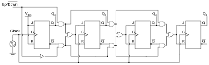
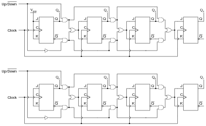
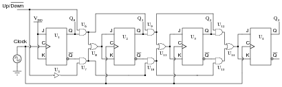
Shown here is an up/down synchronous counter design that does work:
|
|
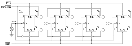
Explain why this circuit is able to function properly (counting in either direction), while the first circuit is not able to count properly at all. What do those ëxtra" gates do to make the counter circuit function as it should. Hint: to more easily compare the up/down counter to the faulty up counter initially shown, connect the Up/[`Down] control line high, and then disregard any lines and gates that become disabled as a result.
Notes:
Although the up/down counter circuit may look overwhelmingly complex at first, it is actually quite simple once students recognize the intent of the AND and OR gates: to ßelect" either the Q or [`Q] signal to control subsequent flip-flops.
Question 9:
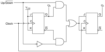
The following circuit is a two-bit synchronous binary up/down counter:
|
|
Explain what would happen if the upper AND gate's output were to become ßtuck" in the high state regardless of its input conditions. What effect would this kind of failure have on the counter's operation?
Notes:
The purpose of this question is to get students to understand how a synchronous up/down counter works, in the context of analyzing the effects of a component failure.
Question 10:
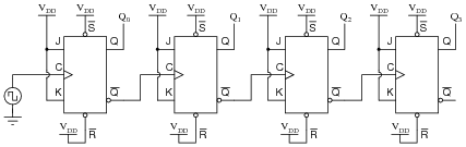
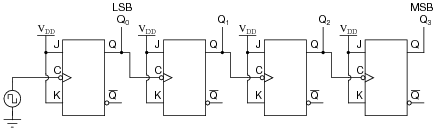
Supposed we used J-K flip-flops with asynchronous inputs (Preset and Clear) to build a counter:
|
|
With the asynchronous lines paralleled as such, what are we able to make the counter do now that we weren't before we had asynchronous inputs available to us?
Notes:
Ask your students why this feature might be useful. Can they think of any applications involving a counter circuit where it would be practical to force its output to either zero or full count regardless of the clock's action?
Question 11:
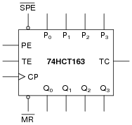
The part number 74HCT163 integrated circuit is a high-speed CMOS, four-bit, synchronous binary counter. It is a pre-packaged unit, will all the necessary flip-flops and selection logic enclosed to make your design work easier than if you had to build a counter circuit from individual flip-flops. Its block diagram looks something like this (power supply terminals omitted, for simplicity):
|
|
Research the function of this integrated circuit, from manufacturers' datasheets, and explain the function of each input and output terminal.
- �
- P0, P1, P2, and P3 = parallel load data inputs
- �
- Q0, Q1, Q2, and Q3 = count outputs
- �
- CP = Clock pulse input
- �
- [`MR] = Master reset input
- �
- [`SPE] = Synchronous parallel enable input
- �
- PE = Enable input
- �
- TE = Enable input
- �
- TC = Terminal count output (sometimes called ripple carry output, or RCO)
Follow-up question: both the reset ([`MR]) and preset ([`SPE]) inputs are synchronous for this particular counter circuit. Explain the significance of this fact in regard to how we use this IC.
Notes:
Ultimately, your students will most likely be working with pre-packaged counters more often than counters made up of individual flip-flops. Thus, they need to understand the nomenclature of counters, their common pin functions, etc. If possible, allow for the group presentation of datasheets by having a computer projector available, so students may show the datasheets they've downloaded from the internet to the rest of the class.
Something your students may notice when researching datasheets is how different manufacturers give the same IC pins different names. This may make the interpretation of inputs and outputs on the given symbol more difficult, if the particular datasheet researched by the student does not use the same labels as I do! This is a great illustration of datasheet variability, covered in a way that students are not likely to forget.
Question 12:
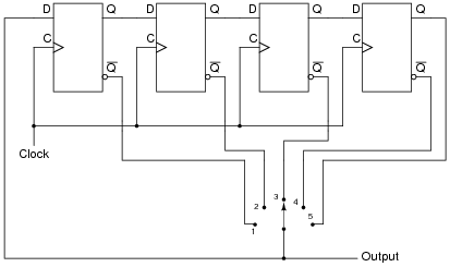
Determine the output pulses for this counter circuit, known as a Johnson counter, assuming that all Q outputs begin in the low state:
|
|
|
|
|
|
Follow-up question: if used as a frequency divider, what is the input:output ratio of this circuit? How difficult would it be to design a Johnson counter with a different division ratio?
Notes:
Discuss with your students how Johnson counters are quite different from binary-sequence counters, and how this uniqueness allows certain counting functions to be implemented much easier (using fewer gates) than other types of counter circuits.
Question 13:
The following circuit is known as a Johnson counter:
|
|
Describe the output of this circuit, as measured from the Q output of the far right flip-flop, assuming that all flip-flops power up in the reset condition.
Also, explain what this modified version of the above Johnson counter circuit will do, in each of the five selector switch positions:
|
|
Notes:
Strictly speaking, this circuit is a divide-by-2n counter, because the frequency division ratio is equal to twice the number of flip-flops.
The final (#5) switch position is interesting, and should be discussed among you and your students.
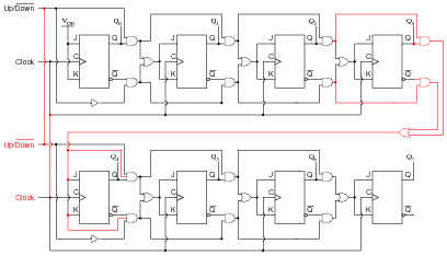
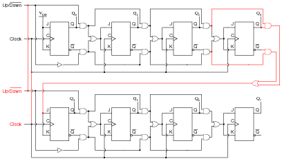
Question 14:
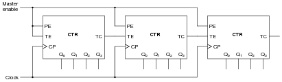
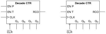
Suppose we had two four-bit synchronous up/down counter circuits, which we wished to cascade to make one eight-bit counter. Draw the necessary connecting wires (and any extra gates) between the two four-bit counters to make this possible:
|
|
After deciding how to cascade these counters, imagine that you are in charge of building and packaging four-bit counter circuits. The customers who buy your counters might wish to cascade them as you did here, but they won't have the ability to "go inside" the packaging as you did to connect to any of the lines between the various flip-flops. This means you will have to provide any necessary cascading lines as inputs and outputs on your pre-packaged counters. Think carefully about how you would choose to build and package your four-bit "cascadable" counters, and then draw a schematic diagram.
|
|
. . . while this solution does only requires different AND gates (3-input instead of 2-input) on the first flip-flop stage of the second counter:
|
|
I'll let you decide how you might wish to package your four-bit counter circuits, so as to allow easy cascading. This will be an excellent topic for classroom discussion!
Follow-up question: why isn't the following circuit an acceptable solution?
|
|
Notes:
Figuring out how to cascade the two four-bit counters is the easy part. The challenge is to "think ahead" in designing a four-bit counter with all the necessary connections to make cascading easy for the end-user. Make this the center of discussion on this particular question.
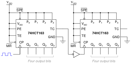
Question 15:
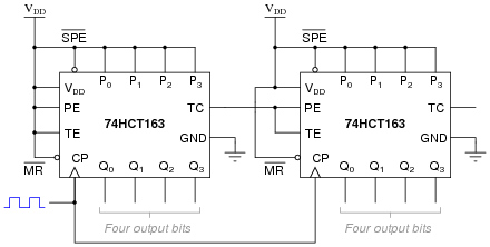
Here is an eight-bit counter comprised of two four-bit 74HCT163 synchronous binary counters cascaded together:
|
|
Explain how this counter circuit works, and also determine which output bit is the LSB and which is the MSB.
Now, examine this eight-bit counter comprised of the same two ICs:
|
|
Explain how this counter circuit works, and how its operation differs from the previous eight-bit counter circuit.
Follow-up question: comment on which method of cascading is preferred for this type of counter IC. Is the functional difference between the two circuits significant enough to warrant concern?
Notes:
It is important for students to consult the datasheet for the 74HCT163 counter circuit in order to fully understand what is going on in these two cascaded counter circuits.
Question 16:
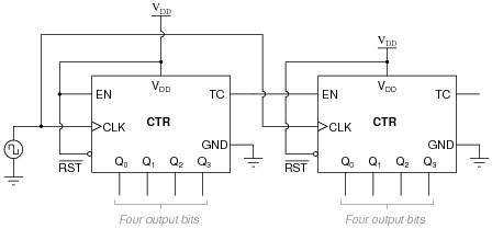
A student wishes to cascade multiple four-bit synchronous counters together. His first effort looks like this, and it works well as an eight-bit counter:
|
|
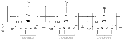
Encouraged by this success, the student decides to add another four-bit counter to the end to make a twelve-bit counter circuit:
|
|
Unfortunately, this arrangement does not work so well. It seems to work good for the first 241 counts (from 000000000000 to 000011110000), but then the last four bits begin to cycle as quickly as the first four bits, while the middle four bits remain in the 1111 state for 15 additional clock pulses. Something is definitely very wrong here!
Determine what the problem is, and suggest a remedy for it. Hint: this situation is very similar to connecting more than two J-K flip-flops together to form a synchronous counter circuit.
Notes:
The "hint" in this question may give away too much, as the problem is precisely identical to the problem encountered with overly simplistic synchronous J-K flip-flop cascades. What new students tend to overlook is the necessity to enable successive stages only when all preceding stages are at their terminal counts. When you only have two stages (two J-K flip-flops or two IC counters) to deal with, there is only one TC output to be concerned with, and the problem never reveals itself.
Be sure to give your students time and opportunity to present their solutions to this dilemma. Ask them how they arrived at their solutions, whether by textbook, prior example (with J-K flip-flops), or perhaps sheer brain power.
Question 17:
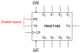
Some integrated circuit counters come equipped with multiple enable inputs. A good example of this is the 74HCT163:
|
|
In this case, as in others, the two enable inputs are not identical. Although both must be active for the counter to count, one of the enable inputs does something extra that the other one does not. This additional function is often referred to as a look-ahead carry, provided to simplify cascading of counters.
Explain what "look-ahead carry" means in the context of digital counter circuits, and why it is a useful feature.
|
|
Notes:
The important lesson in this question is that synchronous counter circuits with more than two stages need to be configured in such a way that all higher-order stages are disabled with the terminal count of the lowest-order stage is inactive. This ensures a proper binary count sequence throughout the overall counter circuit's range. Your students should have been introduced to this concept when studying synchronous counter circuits made of individual J-K flip-flops, and it is the same concept here.
Also important here is the realization that some IC counters come equipped with the "look-ahead" feature built in, and students need to know how and why to use this feature.
Question 18:
Determine the modulus (MOD) of a four-bit binary counter. Determine the modulus of two four-bit binary counters cascaded to make an eight-bit binary counter.
Eight bit counter modulus = 256.
Follow-up question: is it possible for a four-bit counter to have a modulus equal to some value other than 16? Give an example!
Notes:
The real purpose of this question is to get students to find out what term "modulus" means, and how it relates to counter bits.
Question 19:
Consider the following four-bit binary counter integrated circuit (IC). When clocked by the square wave signal generator, it counts from 0000 to 1111 in sixteen steps and then "recycles" back to 0000 again in a single step:
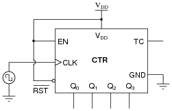
|
|
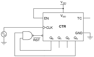
There are many applications, though, where we do not wish the counter circuit to count all the way up to full count (1111), but rather recycle at some lesser terminal count value. Take for instance the application of BCD counting: from 0000 to 1001 and back again. Here is one way to truncate the counting sequence of a binary counter so that it becomes a BCD counter:
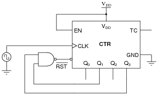
|
|
Explain how the NAND gate forces this counter to recycle after an output of 1001 instead of counting all the way up to 1111. (Hint: the reset function of this IC is assumed to be asynchronous, meaning the counter output resets to 0000 immediately when the [`RST] terminal goes low.)
Also, show how you would modify this circuit to do the same count sequence (BCD) assuming the IC has a synchronous reset function, meaning the counter resets to 0000 if [`RST] is low and the clock input sees a pulse.
|
|
Notes:
Although both circuits achieve a BCD count sequence, the synchronous-reset circuit is preferred because it completely avoids spurious ("ripple-like") false outputs when recycling. Be sure to emphasize that the difference between an asynchronous and a synchronous reset function is internal to the IC, and not something the user (you) can change. For an example of two otherwise identical counters with different reset functions, compare the 74HCT161 (asynchronous) and 74HCT163 (synchronous) four-bit binary counters.
Question 20:
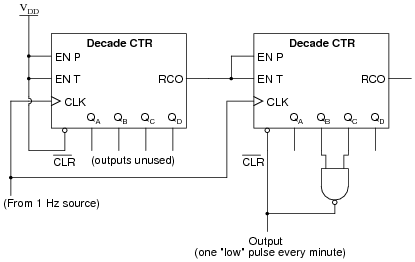
Suppose you had an astable multivibrator circuit that output a very precise 1 Hz square-wave signal, but you had an application which requires a pulse once every minute rather than once every second. Knowing that there are 60 seconds in a minute, can you think of a way to use digital counters to act as a "frequency divider" so that every 60 multivibrator pulses equates to 1 output pulse?
You don't have a divide-by-60 counter available, but you do have several divide-by-10 ("decade") counters at your disposal. Engineer a solution using these counter units:
|
|
Note: assume these counter ICs have asynchronous resets.
|
|
Follow-up question: why can't we take the divide-by-60 pulse from the RCO output of the second counter, as we could with the divide-by-10 pulse from the first counter?
Challenge question: re-design this circuit so that the output is a square wave with a duty cycle of 50% ("high" for 30 seconds, then "low" for 30 seconds), rather than a narrow pulse every 60 seconds.
Notes:
Tell your students that counter circuits are quite often used as frequency dividers. Discuss the challenge question with them, letting them propose and discuss multiple solutions to the problem.
The "note" in the question about the asynchronous nature of the counter reset inputs is very important, as synchronous-reset counter ICs would not behave the same. Discuss this with your students, showing them how counters with synchronous reset inputs would yield a divide-by-61 ratio.
Incidentally, a divide-by-60 counter circuit is precisely what we would need to arrive at a 1 Hz pulse waveform from a 60 Hz powerline frequency signal, which is a neat "trick" for obtaining a low-speed clock of relatively good accuracy without requiring a crystal-controlled local oscillator. (Where the "mains" power is 50 Hz instead of 60 Hz, you would need a divide-by-50 counter - I know, I know . . .) If time permits, ask your students to think of how they could condition the 60Hz sine-wave (120 volt!) standard powerline voltage into a 60 Hz square-wave pulse suitable for input into such a frequency divider/counter circuit.
Question 21:
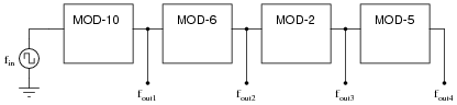
When counters are used as frequency dividers, they are often drawn as simple boxes with one input and one output each, like this:
|
|
Calculate the four output frequencies (fout1 through fout4) given an input frequency of 1.5 kHz:
- �
- fout1 =
- �
- fout2 =
- �
- fout3 =
- �
- fout4 =
- �
- fout1 = 150 Hz
- �
- fout2 = 25 Hz
- �
- fout3 = 12.5 Hz
- �
- fout4 = 2.5 Hz
Follow-up question: if the clock frequency for this divider circuit is exactly 1.5 kHz, is it possible for the divided frequencies to vary from what is predicted by the modulus values (150 Hz, 25 Hz, 12.5 Hz, and 2.5 Hz)? Explain why or why not.
Notes:
The purpose of this question is to introduce students to the schematic convention of counter/dividers as simple boxes with "MOD" specified for each one, and to provide a bit of quantitative analysis (albeit very simple).
Question 22:
A student builds a four-bit asynchronous counter circuit using CMOS J-K flip-flops. It seems to work . . . most of the time. Every once in a while, the count suddenly and mysteriously "jumps" out of sequence, to a value that is completely wrong. Even stranger than this is the fact that it seems to happen every time the student waves their hand next to the circuit.
What do you suspect the problem to be?
Notes:
I didn't exactly reveal the source of trouble in the answer, but I gave enough hints that anyone familiar with CMOS should be able to tell what it is! This truly is a problem I've seen many times with my students!
Question 23:
Identify a single fault that would allow this synchronous counter circuit to count up on demand, but not down:
|
|
Explain why your proposed fault would cause the problem.
Notes:
Discuss the merit of all faults proposed in answer to this question with your students. Ask them to explain the reasoning behind their answers, and use this as an opportunity to correct conceptual errors about the operation of this circuit.
Question 24:
A student builds a four-bit asynchronous up counter out of individual J-K flip-flops, but is dissatisfied with its performance:
|
|
Although the counting sequence is proper, the circuit usually does not begin counting from 0000 at power-up. The fact that the circuit counts correctly suggests that there is nothing failed or mis-wired, so what could possibly be wrong?
Notes:
This is a very practical issue for state-machine circuits: making sure the circuit begins in the desired state rather than in some random condition.
Question 25:
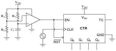
The following RC circuit constitutes an automatic reset network for the counter. At power-up, it resets the counter to 0000, then allows it to count normally:
|
|
Predict how the operation of this automatic reset circuit will be affected as a result of the following faults. Consider each fault independently (i.e. one at a time, no multiple faults):
- �
- Resistor R1 fails open:
- �
- Resistor R2 fails open:
- �
- Resistor R3 fails open:
- �
- Capacitor C1 fails shorted:
For each of these conditions, explain why the resulting effects will occur.
- �
- Resistor R1 fails open: Counter may not reset at power-up.
- �
- Resistor R2 fails open: Counter will not count, output stuck at 0000.
- �
- Resistor R3 fails open: Counter will not count, output stuck at 0000.
- �
- Capacitor C1 fails shorted: Counter will not count, output stuck at 0000.
Follow-up question: suggest some reasonable values for the three resistors and the capacitor.
Notes:
The purpose of this question is to approach the domain of circuit troubleshooting from a perspective of knowing what the fault is, rather than only knowing what the symptoms are. Although this is not necessarily a realistic perspective, it helps students build the foundational knowledge necessary to diagnose a faulted circuit from empirical data. Questions such as this should be followed (eventually) by other questions asking students to identify likely faults based on measurements.
Question 26:
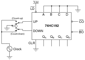
A student is trying to get a 74HC192 up/down counter to function. However, it is simply not cooperating:
|
|
Determine what the student is doing wrong with this 74HC192, and then correct the schematic diagram.
Notes:
The point of this question is to have students research a datasheet to figure out the necessary conditions for making a digital IC perform as it should. This is extremely important for students to get into the habit of doing, as it will save them much trouble as technicians!
Question 27:
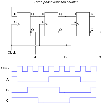
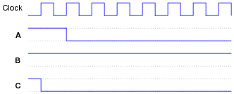
This Johnson counter circuit is special. It outputs three square-wave signals, shifted 120o from one another:
|
|
Suppose the middle flip-flop's Q output fails in the "high" state. Plot the new output waveforms for signals A, B, and C. Assume all Q outputs begin in the "low" state (except for the middle flip-flop, of course):
|
|
|
|
Notes:
The purpose of this question is to approach the domain of circuit troubleshooting from a perspective of knowing what the fault is, rather than only knowing what the symptoms are. Although this is not necessarily a realistic perspective, it helps students build the foundational knowledge necessary to diagnose a faulted circuit from empirical data. Questions such as this should be followed (eventually) by other questions asking students to identify likely faults based on measurements.
Question 28:
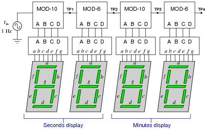
A technician is trying to build a timer project using a set of cascaded counters, each one connected to its own 7-segment decoder and display:
|
|
The technician was trying to troubleshoot this circuit, but left without finishing the job. You were sent to finish the work, having only been told that the timer circuit "has some sort of problem." Your first step is to start the 1 Hz clock and watch the timing sequence, and after a few minutes of time you fail to notice anything out of the ordinary.
Now, you could sit there for a whole hour and watch the count sequence, but that might take a long time before anything unusual appears for you to see. Devise a test procedure that will allow you to pinpoint problems at a much faster rate.
Follow-up question: suppose you did this and found no problem at all. What would you suspect next as a possible source of trouble that could cause the timer circuit to time incorrectly?
Notes:
Connecting a faulty circuit to a different input signal than what it normally runs at is an excellent way to explore faults. However, it should be noted that some faults may go undetected using this technique, because you have altered the circuit in the process.
Question 29:
Explain the difference between a synchronous counter and an asynchronous counter circuit.
Notes:
Ask your students to discuss what advantages, if any, one of these counter circuit types may have over the other.
Question 30:
Draw the schematic diagram for a four-bit binary üp" counter circuit, using J-K flip-flops.
|
|
Follow-up question: what other configuration of J-K flip-flops could be used to make a four bit binary üp" counter?
Notes:
Be sure to discuss the follow-up question with your students. It is important that they understand how to make both üp" and "down" counters using J-K flip-flops, and that there are two basic methods to make each direction of counter.
Question 31:
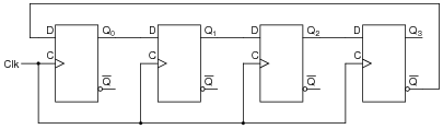
Complete a timing diagram for this circuit, and determine its direction of count, and also whether it is a synchronous counter or an asynchronous counter:

|
|

|
|

|
|
Notes:
"Walk" through the timing diagram given in the answer, and have students explain how the logic states correspond to a two-bit binary counting sequence.
Question 32:
Complete a timing diagram for this circuit, and determine its direction of count, and also whether it is a synchronous counter or an asynchronous counter:
|
|

|
|
|
|
Notes:
"Walk" through the timing diagram given in the answer, and have students explain how the logic states correspond to a two-bit binary counting sequence.
Question 33:
Complete a timing diagram for this circuit, and determine its direction of count, and also whether it is a synchronous counter or an asynchronous counter:
|
|
|
|
Notes:
"Walk" through the timing diagram given in the answer, and have students explain how the logic states correspond to a two-bit binary counting sequence.
Question 34:
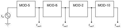
When counters are used as frequency dividers, they are often drawn as simple boxes with one input and one output each, like this:
|
|
Calculate the four output frequencies (fout1 through fout4) given an input frequency of 25 kHz:
- �
- fout1 =
- �
- fout2 =
- �
- fout3 =
- �
- fout4 =
- �
- fout1 = 5 kHz
- �
- fout2 = 625 Hz
- �
- fout3 = 312.5 Hz
- �
- fout4 = 31.25 Hz
Follow-up question: if the clock frequency for this divider circuit is exactly 25 kHz, is it possible for the divided frequencies to vary from what is predicted by the modulus values (5 kHz, 625 Hz, 312.5 Hz, and 31.25 Hz)? Explain why or why not.
Notes:
The purpose of this question is to introduce students to the schematic convention of counter/dividers as simple boxes with "MOD" specified for each one, and to provide a bit of quantitative analysis (albeit very simple).