Series DC circuits
Question 1:
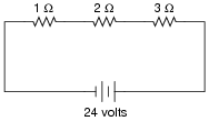
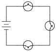
In this circuit, three resistors receive the same amount of current (4 amps) from a single source. Calculate the amount of voltage "dropped" by each resistor, as well as the amount of power dissipated by each resistor:
|
|
E2 W = 8 volts
E3 W = 12 volts
P1 W = 16 watts
P2 W = 32 watts
P3 W = 48 watts
Follow-up question: Compare the direction of current through all components in this circuit with the polarities of their respective voltage drops. What do you notice about the relationship between current direction and voltage polarity for the battery, versus for all the resistors? How does this relate to the identification of these components as either sources or loads?
Notes:
The answers to this question should not create any surprises, especially when students understand electrical resistance in terms of friction: resistors with greater resistance (more friction to electron motion) require greater voltage (push) to get the same amount of current through them. Resistors with greater resistance (friction) will also dissipate more power in the form of heat, given the same amount of current.
Another purpose of this question is to instill in students' minds the concept of components in a simple series circuit all sharing the same amount of current.
Challenge your students to recognize any mathematical patterns in the respective voltage drops and power dissipations. What can be said, mathematically, about the voltage drop across the 2 W resistor versus the 1 W resistor, for example?
Question 2:
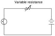
The brightness of a light bulb - or the power dissipated by any electrical load, for that matter - may be varied by inserting a variable resistance in the circuit, like this:
|
|
This method of electrical power control is not without its disadvantages, though. Consider an example where the circuit current is 5 amps, the variable resistance is 2 W, and the lamp drops 20 volts of voltage across its terminals. Calculate the power dissipated by the lamp, the power dissipated by the variable resistance, and the total power provided by the voltage source. Then, explain why this method of power control is not ideal.
Presistance = 50 watts
Ptotal = 150 watts
Follow-up question: note how in the original question I offered a set of hypothetical values to use in figuring out why a series rheostat (variable resistance) is not an efficient means to control lamp power. Explain how the assumption of certain values is a useful problem-solving technique in cases where no values are given to you.
Notes:
Discuss the concept of energy conservation: that energy can neither be created nor destroyed, but merely changed between different forms. Based on this principle, the sum of all power dissipations in a circuit must equal the total amount of power supplied by the energy source, regardless of how the components are connected together.
Question 3:
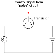
A modern method of electrical power control involves inserting a fast-operating switch in-line with an electrical load, to switch power on and off to it very rapidly over time. Usually, a solid-state device such as a transistor is used:
|
|
This circuit has been greatly simplified from that of a real, pulse-control power circuit. Just the transistor is shown (and not the "pulse" circuit which is needed to command it to turn on and off) for simplicity. All you need to be aware of is the fact that the transistor operates like a simple, single-pole single-throw (SPST) switch, except that it is controlled by an electrical current rather than by a mechanical force, and that it is able to switch on and off millions of times per second without wear or fatigue.
If the transistor is pulsed on and off fast enough, power to the light bulb may be varied as smoothly as if controlled by a variable resistor. However, there is very little energy wasted when using a fast-switching transistor to control electrical power, unlike when a variable resistance is used for the same task. This mode of electrical power control is commonly referred to as Pulse-Width Modulation, or PWM.
Explain why PWM power control is much more efficient than controlling load power by using a series resistance.
Notes:
Students may have a hard time grasping how a light bulb may be dimmed by turning it on and off really fast. The key to understanding this concept is to realize that the transistor's switching time must be much faster than the time it takes for the light bulb's filament to fully heat or fully cool. The situation is analogous to throttling the speed of an automobile by rapidly "pumping" the accelerator pedal. If done slowly, the result is a varying car speed. If done rapidly enough, though, the car's mass averages the ÖN"/ÖFF" cycling of the pedal and results in a nearly steady speed.
This technique is very popular in industrial power control, and is gaining popularity as an audio amplification technique (known as Class D). The benefits of minimal wasted power by the control device are many.
Question 4:
| Don't just sit there! Build something!! |
Learning to mathematically analyze circuits requires much study and practice. Typically, students practice by working through lots of sample problems and checking their answers against those provided by the textbook or the instructor. While this is good, there is a much better way.
You will learn much more by actually building and analyzing real circuits, letting your test equipment provide the änswers" instead of a book or another person. For successful circuit-building exercises, follow these steps:
- 1.
- Carefully measure and record all component values prior to circuit construction.
- 2.
- Draw the schematic diagram for the circuit to be analyzed.
- 3.
- Carefully build this circuit on a breadboard or other convenient medium.
- 4.
- Check the accuracy of the circuit's construction, following each wire to each connection point, and verifying these elements one-by-one on the diagram.
- 5.
- Mathematically analyze the circuit, solving for all values of voltage, current, etc.
- 6.
- Carefully measure those quantities, to verify the accuracy of your analysis.
- 7.
- If there are any substantial errors (greater than a few percent), carefully check your circuit's construction against the diagram, then carefully re-calculate the values and re-measure.
Avoid very high and very low resistor values, to avoid measurement errors caused by meter "loading". I recommend resistors between 1 kW and 100 kW, unless, of course, the purpose of the circuit is to illustrate the effects of meter loading!
One way you can save time and reduce the possibility of error is to begin with a very simple circuit and incrementally add components to increase its complexity after each analysis, rather than building a whole new circuit for each practice problem. Another time-saving technique is to re-use the same components in a variety of different circuit configurations. This way, you won't have to measure any component's value more than once.
Notes:
It has been my experience that students require much practice with circuit analysis to become proficient. To this end, instructors usually provide their students with lots of practice problems to work through, and provide answers for students to check their work against. While this approach makes students proficient in circuit theory, it fails to fully educate them.
Students don't just need mathematical practice. They also need real, hands-on practice building circuits and using test equipment. So, I suggest the following alternative approach: students should build their own "practice problems" with real components, and try to mathematically predict the various voltage and current values. This way, the mathematical theory "comes alive," and students gain practical proficiency they wouldn't gain merely by solving equations.
Another reason for following this method of practice is to teach students scientific method: the process of testing a hypothesis (in this case, mathematical predictions) by performing a real experiment. Students will also develop real troubleshooting skills as they occasionally make circuit construction errors.
Spend a few moments of time with your class to review some of the "rules" for building circuits before they begin. Discuss these issues with your students in the same Socratic manner you would normally discuss the worksheet questions, rather than simply telling them what they should and should not do. I never cease to be amazed at how poorly students grasp instructions when presented in a typical lecture (instructor monologue) format!
A note to those instructors who may complain about the "wasted" time required to have students build real circuits instead of just mathematically analyzing theoretical circuits:
What is the purpose of students taking your course?
If your students will be working with real circuits, then they should learn on real circuits whenever possible. If your goal is to educate theoretical physicists, then stick with abstract analysis, by all means! But most of us plan for our students to do something in the real world with the education we give them. The "wasted" time spent building real circuits will pay huge dividends when it comes time for them to apply their knowledge to practical problems.
Furthermore, having students build their own practice problems teaches them how to perform primary research, thus empowering them to continue their electrical/electronics education autonomously.
In most sciences, realistic experiments are much more difficult and expensive to set up than electrical circuits. Nuclear physics, biology, geology, and chemistry professors would just love to be able to have their students apply advanced mathematics to real experiments posing no safety hazard and costing less than a textbook. They can't, but you can. Exploit the convenience inherent to your science, and get those students of yours practicing their math on lots of real circuits!
Question 5:
The formula for calculating total resistance of three series-connected resistors is as follows:
|
Algebraically manipulate this equation to solve for one of the series resistances (R1) in terms of the other two series resistances (R2 and R3) and the total resistance (R). In other words, write a formula that solves for R1 in terms of all the other variables.
|
Notes:
This question is nothing more than practice algebraically manipulating equations. Ask your students to show you how they solved it, and how the two given answers are equivalent.
Question 6:
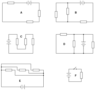
Identify which of these circuits is a series circuit (there may be more than one shown!):
|
|
Notes:
The purpose of this question is to get students to identify what distinguishing characteristic uniquely identifies a circuit as being ßeries." Once this has been identified, there are several conclusions which may be deduced (regarding voltage drops, currents, resistances, etc.).
Circuit F is thrown in the mix just to show students that the non-battery components don't have to all be the same (resistors) in order for a circuit to qualify as ßeries."
Question 7:
Most flashlights use multiple 1.5 volt batteries to power a light bulb with a voltage rating of several volts. Draw a schematic diagram of showing how multiple batteries may be connected to achieve a total voltage greater than any one of the batteries' individual voltages.
|
|
Follow-up question: if each of these batteries outputs a voltage of 1.5 volts, how much voltage does the light bulb experience?
Notes:
Ask the students where they would place a switch to control the light bulb in the circuit shown in the answer.
Question 8:
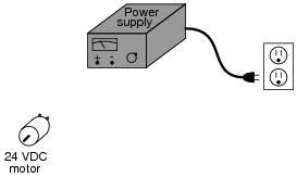
A technician wants to energize a 24 volt motor, but lacks a 24 volt battery to do it with. Instead, she has access to several "power supply" units which convert 120 volt AC power from a power receptacle into low-voltage DC power that is adjustable over a range of 0 to 15 volts. Each of these power supplies is a box with a power cord, voltage adjustment knob, and two output terminals for connection with the DC voltage it produces:
|
|
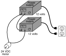
Draw a picture of how this technician might use power supplies to energize the 24 volt motor.
|
|
Notes:
Although this is a very simple and direct solution, it is not the only possible one. Incidentally, this scenario is very common in electronics work: having to couple multiple power supplies together to achieve a desired total voltage or total current.
Question 9:
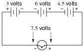
How much voltage does the light bulb receive in this circuit? Explain your answer.
|
|
Also, identify the polarity of the voltage across the light bulb (mark with "+" and "-" signs).
|
|
Follow-up question: draw the direction of current in this circuit.
Notes:
This is a very fundamental concept that students must learn: how to determine the total voltage in a series circuit where opposing voltage sources exist. One thing mistake students sometimes make is to try to discern polarity by looking at the polarity signs at the end terminals of the end battery; i.e. at the 3-volt battery's left-hand terminal, and the 4.5-volt battery's right-hand terminal, then try to transfer those signs down to the load terminals. This is not an accurate way to tell polarity, but it seems to "work" for them in some situations. This problem is one example of a situation where this faulty technique most definitely does not work!
Have your students collectively agree on a procedure they may use to accurate discern series voltage sums and polarities. Guide their discussion, helping them identify principles that are true and valid for all series circuits.
Question 10:
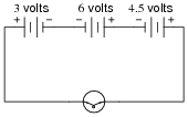
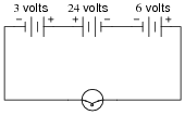
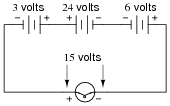
How much voltage does the light bulb receive in this circuit? Explain your answer.
|
|
Also, identify the polarity of the voltage across the light bulb (mark with "+" and "-" signs).
|
|
Follow-up question: being that 30 volts is the commonly accepted "danger" threshold voltage for electric shock, determine whether or not this particular circuit poses a shock hazard.
Notes:
This is a very fundamental concept that students must learn: how to determine the total voltage in a series circuit where opposing voltage sources exist. One thing mistake students sometimes make is to try to discern polarity by looking at the polarity signs at the end terminals of the end battery; i.e. at the 3-volt battery's left-hand terminal, and the 4.5-volt battery's right-hand terminal, then try to transfer those signs down to the load terminals. This is not an accurate way to tell polarity, but it seems to "work" for them in some situations. This problem is one example of a situation where this faulty technique most definitely does not work!
Have your students collectively agree on a procedure they may use to accurate discern series voltage sums and polarities. Guide their discussion, helping them identify principles that are true and valid for all series circuits.
With regard to the safety question, there is more to determining risk of shock than a simple voltage check. It is important for your students to realize this, despite äccepted" thresholds for hazardous voltage and such.
Question 11:
Re-draw this circuit in the form of a schematic diagram:
|
|
|
|
Notes:
One of the more difficult skills for students to develop is the ability to translate the layout of a real-world circuit into a neat schematic diagram. Developing this skill requires lots of practice.
It is very worthwhile for students to discuss how they solve problems such as these with each other. For those students who have trouble visualizing shapes, a simple hint or "trick" to use when translating schematics to illustrations or visa-versa may be invaluable.
Question 12:
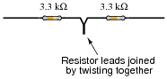
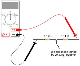
Suppose I connect two resistors in series with one another, like this:
|
|
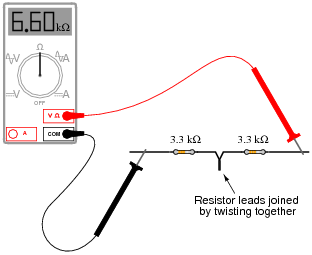
How much electrical resistance would you expect an ohmmeter to indicate if it were connected across the combination of these two series-connected resistors?
|
|
Explain the reasoning behind your answer, and try to formulate a generalization for all combinations of series resistances.
|
|
Follow-up question: how much resistance would you expect the ohmmeter to register if there were three similarly-sized resistors connected in series instead of two? What if there were four resistors?
Notes:
The concept of series (total) resistance, in relation to individual resistances, usually does not present any difficulties to new students. Parallel resistances are a bit trickier, though . . .
Question 13:
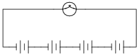
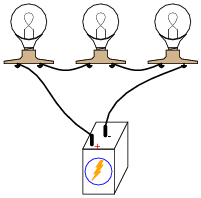
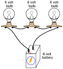
What would happen if three 6-volt light bulbs were connected as shown to a 6-volt battery? How would their brightnesses compare to just having a single 6-volt light bulb connected to a 6-volt battery?
|
|
Notes:
Here, the important principle of voltage "drops" in a series circuit is highlighted. This question serves to further define, in practical ways, what the term ßeries" really means.
Question 14:
Qualitatively compare the voltage and current for each of the three light bulbs in this circuit (assume the three light bulbs are absolutely identical):

|
|
Notes:
Here, the important principles of voltage and current in a series circuit are highlighted. This question serves to further define, in practical ways, what the term ßeries" really means.
An important lesson of this question is the distinction between measurements which are guaranteed to be equal versus measurements which just happen to be equal for a given selection of components.
Question 15:
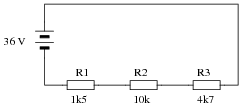
Explain, step by step, how to calculate the amount of current (I) that will go through each resistor in this series circuit, and also the voltage (V) dropped by each resistor:
|
|
- IR1 = 2.22 mA ; VR1 = 3.33 V
- IR2 = 2.22 mA ; VR2 = 22.2 V
- IR3 = 2.22 mA ; VR3 = 10.4 V
Notes:
Students often just want to memorize a procedure for determining answers to questions like these. Challenge your students to not only understand the procedure, but to also explain why it must be followed.
Something your students will come to realize in discussion is that there is more than one way to arrive at all the answers! While some of the steps will be common to all calculation strategies, other steps (near the end) leave room for creativity.
Note to your students that European symbols are used throughout this schematic diagram.
Question 16:
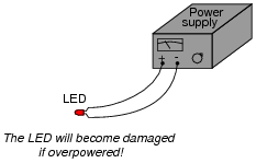
Light-emitting diodes, or LEDs, are rugged and highly efficient sources of light. They are far more rugged and efficient than incandescent lamps, and they also have the ability to switch on and off much faster because there is no filament inside needing to heat or cool:

|
|
LEDs are low voltage devices, typically rated in the range of 1.5 to 2 volts DC maximum. Single diodes generally draw low currents as well, about 20 milliamps each. The problem is, how do you operate an LED from a typical electronic power source, which may output 24 volts DC or more?
|
|
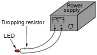
The answer is to use a series dropping resistor:
|
|
Calculate the necessary resistance value and minimum power rating of a series dropping resistor for an LED rated at 1.7 volts and 20 mA, and a power supply voltage of 24 volts.
Follow-up question: if there were no 1115 W resistors to choose from (which there most likely will not be!), would it be safer to choose a higher-value resistor or a lower-value resistor for this application? For example, if your only choices in 1/2 watt resistors were a 1 kW and a 1.2 kW, which one would you choose? Explain your answer.
Notes:
The follow-up question is a very practical one, for it is seldom that you have the exact components on-hand to match the requirements of a circuit you are building. It is important to understand which way is safer to err (too large or too small) when doing äs-built" design work.
Question 17:
Calculate the necessary series "dropping" resistor value to operate a 1.6 volt, 20 mA LED from a 15 volt DC power source. Also, calculate the power dissipated by the resistor while operating.
R = PR =
Notes:
Ask your students to explain how they calculated the correct answer for this question.
Question 18:
Calculate the necessary series "dropping" resistor value to operate a 1.8 volt, 20 mA LED from a 34 volt DC power source. Also, calculate the power dissipated by the resistor while operating.
R = PR =
Notes:
Ask your students to explain how they calculated the correct answer for this question.
Question 19:
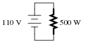
Suppose that an electric heater, which is nothing more than a large resistor, dissipates 500 watts of power when directly connected to a 110 volt source:
|
|
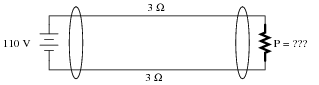
Now suppose that exact same heater is connected to one end of a long two-wire cable, which is then connected to the same 110 volt source. Assuming that each conductor within the cable has an end-to-end resistance of 3 ohms, how much power will the heater dissipate?
|
|
Notes:
The purpose of this question, besides providing a good problem-solving exercise for students, is to get them to realize one of the practical implications of power-line resistance.
Question 20:
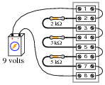
The circuit shown here is commonly referred to as a voltage divider. Calculate the voltage dropped across the following pairs of terminals, the current through each resistor, and the total amount of electrical resistance ßeen" by the 9-volt battery:
|
|
- �
- Voltage between terminals 2 and 3 =
- �
- Voltage between terminals 4 and 5 =
- �
- Voltage between terminals 6 and 7 =
- �
- Voltage between terminals 6 and 8 =
- �
- Voltage between terminals 4 and 8 =
- �
- Voltage between terminals 2 and 8 =
- �
- Current through each resistor =
- �
- Rtotal =
Can you think of any practical applications for a circuit such as this?
- �
- Voltage between terminals 2 and 3 = 1.8 volts
- �
- Voltage between terminals 4 and 5 = 2.7 volts
- �
- Voltage between terminals 6 and 7 = 4.5 volts
- �
- Voltage between terminals 6 and 8 = 4.5 volts
- �
- Voltage between terminals 4 and 8 = 7.2 volts
- �
- Voltage between terminals 2 and 8 = 9 volts
- �
- Current through each resistor = 0.9 mA
- �
- Rtotal = 10 kW
Note how all the voltage drops are a certain proportion of the total voltage. What do you think would happen to these voltage drops if the source voltage (9 volts from the battery) were doubled?
Notes:
Some students may find the diagram hard to follow, and so they will find the task of analysis helped by drawing an equivalent schematic diagram for this circuit, with all terminal points labeled. I recommend you not suggest this solution immediately, but rather challenge your students to think of problem-solving techniques on their own. Surely, someone in the class will have thought of doing this, and the impact of such a suggestion coming from a peer is greater than if it came from you, the instructor.
Be sure to ask your students this question: "Why is this type of circuit commonly called a voltage divider?"
Question 21:
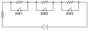
What will happen in this circuit as the switches are sequentially turned on, starting with switch number 1 and ending with switch number 3?
|
|
Describe how the successive closure of these three switches will impact:
- �
- The total amount of circuit resistance ßeen" by the battery
- �
- The total amount of current drawn from the battery
- �
- The current through each resistor
- �
- The voltage drop across each resistor
Also, provide a safety-related reason for the existence of the fourth resistor in this circuit, on the left-hand side of the circuit (not bypassed by any switch).
As the first switch (SW1) is closed, the voltage across resistor R1 will decrease to zero, while the voltages across the remaining resistors will increase. The current through resistor R1 will also decrease to zero, and the current through the remaining resistors will also increase. Each of the resistors will experience the same amount of current as the others, and this amount of current will also be experienced by the battery. Overall, the battery ßees" less total resistance than before.
The fourth resistor is there to prevent a short-circuit from developing if all switches are simultaneously closed.
Notes:
One problem I've encountered while teaching the "laws" of series circuits is that some students mistakenly think the rule of äll currents in a series circuit being the same" means that the amount of current in a series circuit is fixed over time and cannot change. The root of this misunderstanding is memorization rather than comprehension: students memorize the rule "all currents are the same" and think this means the currents must remain the same before and after any change is made to the circuit. I've actually had students complain to me, saying, "But you told us all currents are the same in a series circuit!", as though it were my job to decree perfect and universal Laws which would require no critical thinking on the part of the student. But I digress . . .
This question challenges students' comprehension of series circuit behavior by asking what happens after a change is made to the circuit. The purpose of the switches is to "remove" resistors from the circuit, one at a time, without actually having to remove components.
Question 22:
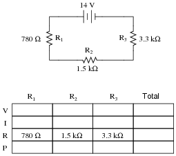
Complete the table of values for this circuit:
|
|
|
|
Follow-up question #1: without performing any mathematical calculations, determine the effects on all the component voltage drops and currents if resistor R1 were to fail open.
Follow-up question #2: without performing any mathematical calculations, determine the effects on all the component voltage drops and currents if resistor R1 were to fail shorted.
Notes:
Discuss with your students what a good procedure might be for calculating the unknown values in this problem, and also how they might check their work.
Question 23:
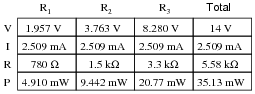
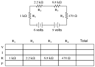
Complete the table of values for this circuit:
|
|
|
|
Follow-up question #1: without performing any mathematical calculations, determine the effects on all the component voltage drops and currents if resistor R2 were to fail open.
Follow-up question #2: without performing any mathematical calculations, determine the effects on all the component voltage drops and currents if resistor R2 were to fail shorted.
Notes:
Discuss with your students what a good procedure might be for calculating the unknown values in this problem, and also how they might check their work.
Question 24:
In a series circuit, certain general rules may be stated with regard to quantities of voltage, current, resistance, and power. Express these rules, using your own words:
Ïn a series circuit, voltage . . ."
Ïn a series circuit, current . . ."
Ïn a series circuit, resistance . . ."
Ïn a series circuit, power . . ."
For each of these rules, explain why it is true.
Ïn a series circuit, current is equal through all components."
Ïn a series circuit, resistances add to equal the total."
Ïn a series circuit, power dissipations add to equal the total."
Notes:
Rules of series and parallel circuits are very important for students to comprehend. However, a trend I have noticed in many students is the habit of memorizing rather than understanding these rules. Students will work hard to memorize the rules without really comprehending why the rules are true, and therefore often fail to recall or apply the rules properly.
An illustrative technique I have found very useful is to have students create their own example circuits in which to test these rules. Simple series and parallel circuits pose little challenge to construct, and therefore serve as excellent learning tools. What could be better, or more authoritative, than learning principles of circuits from real experiments? This is known as primary research, and it constitutes the foundation of scientific inquiry. The greatest problem you will have as an instructor is encouraging your students to take the initiative to build these demonstration circuits on their own, because they are so used to having teachers simply tell them how things work. This is a shame, and it reflects poorly on the state of modern education.
Question 25:
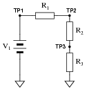
Predict how all test point voltages (measured between each test point and ground) in this circuit will be affected as a result of the following faults. Consider each fault independently (i.e. one at a time, no multiple faults):
|
|
- �
- Resistor R1 fails open:
- �
- Resistor R2 fails open:
- �
- Resistor R3 fails open:
- �
- Solder bridge (short) past resistor R2:
For each of these conditions, explain why the resulting effects will occur.
- �
- Resistor R1 fails open: VTP1 = no change (source voltage), VTP2 = decrease to 0 volts, VTP3 = decrease to 0 volts.
- �
- Resistor R2 fails open: VTP1 = no change (source voltage), VTP2 = increase to full source voltage, VTP3 = decrease to 0 volts.
- �
- Resistor R3 fails open: VTP1 = no change (source voltage), VTP2 = increase to full source voltage, VTP3 = increase to full source voltage.
- �
- Solder bridge (short) past resistor R2: VTP1 = no change (source voltage), VTP2 = decrease, VTP3 = increase, VTP2 = VTP3.
Notes:
The purpose of this question is to approach the domain of circuit troubleshooting from a perspective of knowing what the fault is, rather than only knowing what the symptoms are. Although this is not necessarily a realistic perspective, it helps students build the foundational knowledge necessary to diagnose a faulted circuit from empirical data. Questions such as this should be followed (eventually) by other questions asking students to identify likely faults based on measurements.
Question 26:
A student is troubleshooting a two-resistor voltage divider circuit, using a table to keep track of his test measurements and conclusions. The table lists all components and wires in the circuit so that the student may document their known status with each successive measurement:
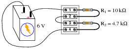
|
|
-
Measurement taken Battery Wire +/1 R1 Wire 2/3 R2 Wire 4/-
Prior to beginning troubleshooting, the student is told there is no voltage across R2. Thus, the very first entry into the table looks like this:
-
Measurement taken Battery Wire +/1 R1 Wire 2/3 R2 Wire 4/-
VR2 = 0 V
Based on this data, the student then determines possible faults which could cause this to happen, marking each possibility in the table using letters as symbols. The assumption here is that there is only one fault in the circuit, and that it is either a complete break (open) or a direct short:
-
Measurement taken Battery Wire +/1 R1 Wire 2/3 R2 Wire 4/-
VR2 = 0 V O O O O S O
Ö" symbolizes a possible öpen" fault, while "S" symbolizes a possible ßhorted" fault.
Next, the student measures between terminals 1 and 4, obtaining a full 6 volt reading. This is documented on the table as well, along with some updated conclusions regarding the status of all wires and components:
-
Measurement taken Battery Wire +/1 R1 Wire 2/3 R2 Wire 4/-
VR2 = 0 V O O O O S O
V1-4 = 6 V OK OK O O S OK
After this, the student measures between terminals 1 and 2 (across resistor R1), and gets a reading of 0 volts. Complete the table based on this last piece of data:
-
Measurement taken Battery Wire +/1 R1 Wire 2/3 R2 Wire 4/-
VR2 = 0 V O O O O S O
V1-4 = 6 V OK OK O O S OK
VR1 = 0 V
-
Measurement taken Battery Wire +/1 R1 Wire 2/3 R2 Wire 4/-
VR2 = 0 V O O O O S O
V1-4 = 6 V OK OK O O S OK
VR1 = 0 V OK OK OK O OK OK
Conclusion: there is an open fault (break) between terminals 2 and 3. This is the only single fault which will account for all the data.
Notes:
The main purpose of this question is to introduce students to this style of documentation and strategy for use in troubleshooting a circuit. For each successive reading, the student is required to re-assess the status of each component, figuring out what single failure could account for all data up to that point.
Question 27:
This voltage divider circuit has a problem: there is no voltage output between terminals 7 and 8.
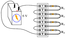
|
|
A technician has taken several measurements with a voltmeter, documenting them chronologically from top to bottom in the far-left column:
-
Measurement Batt (+)/1 R1 2/3 R2 4/5 R3 6/7 R4 8/(-)
V1-8 = 6 V
V1-5 = 0 V
V5-7 = 6 V
Fill in all cells of this table with one of three different symbols, representing the status of each component or wire (numbers separated by a slash indicate the wire connecting those terminals):
- �
- O for an öpen" fault
- �
- S for an ßhort" fault
- �
- OK for no fault
You are to assume that there is only one fault in this circuit, and that it is either a complete break (open) or a direct short (zero resistance). After completing the table, assess whether or not the exact fault may be known from the data recorded thus far. If not, suggest the next logical voltage measurement to take.
-
Measurement Batt (+)/1 R1 2/3 R2 4/5 R3 6/7 R4 8/(-)
V1-8 = 6 V OK OK O O O O O O S OK
V1-5 = 0 V OK OK OK OK OK OK O O S OK
V5-7 = 6 V OK OK OK OK OK OK O O OK OK
We do not yet have enough information to determine whether resistor R3 or wire 6/7 is failed open. A good voltage measurement to take now would be across the resistor (terminals 5 and 6), or between terminals 6 and 7.
Follow-up question: describe how much voltage you would expect to find between either of these terminal pairs, given an open fault with either suspected component.
Notes:
Ask your students to defend their answers for each component status, for each of the successive measurements. What you will find is that this forces students to rigorously analyze the possibilities of a fault in each portion of the circuit. Not only is this beneficial for reinforcing basic circuit principles, but it also teaches students to consider all possibilities when troubleshooting a circuit.