Series-parallel DC circuits
Question 1:
| Don't just sit there! Build something!! |
Learning to mathematically analyze circuits requires much study and practice. Typically, students practice by working through lots of sample problems and checking their answers against those provided by the textbook or the instructor. While this is good, there is a much better way.
You will learn much more by actually building and analyzing real circuits, letting your test equipment provide the änswers" instead of a book or another person. For successful circuit-building exercises, follow these steps:
- 1.
- Carefully measure and record all component values prior to circuit construction.
- 2.
- Draw the schematic diagram for the circuit to be analyzed.
- 3.
- Carefully build this circuit on a breadboard or other convenient medium.
- 4.
- Check the accuracy of the circuit's construction, following each wire to each connection point, and verifying these elements one-by-one on the diagram.
- 5.
- Mathematically analyze the circuit, solving for all values of voltage, current, etc.
- 6.
- Carefully measure those quantities, to verify the accuracy of your analysis.
- 7.
- If there are any substantial errors (greater than a few percent), carefully check your circuit's construction against the diagram, then carefully re-calculate the values and re-measure.
Avoid very high and very low resistor values, to avoid measurement errors caused by meter "loading". I recommend resistors between 1 kW and 100 kW, unless, of course, the purpose of the circuit is to illustrate the effects of meter loading!
One way you can save time and reduce the possibility of error is to begin with a very simple circuit and incrementally add components to increase its complexity after each analysis, rather than building a whole new circuit for each practice problem. Another time-saving technique is to re-use the same components in a variety of different circuit configurations. This way, you won't have to measure any component's value more than once.
Notes:
It has been my experience that students require much practice with circuit analysis to become proficient. To this end, instructors usually provide their students with lots of practice problems to work through, and provide answers for students to check their work against. While this approach makes students proficient in circuit theory, it fails to fully educate them.
Students don't just need mathematical practice. They also need real, hands-on practice building circuits and using test equipment. So, I suggest the following alternative approach: students should build their own "practice problems" with real components, and try to mathematically predict the various voltage and current values. This way, the mathematical theory "comes alive," and students gain practical proficiency they wouldn't gain merely by solving equations.
Another reason for following this method of practice is to teach students scientific method: the process of testing a hypothesis (in this case, mathematical predictions) by performing a real experiment. Students will also develop real troubleshooting skills as they occasionally make circuit construction errors.
Spend a few moments of time with your class to review some of the "rules" for building circuits before they begin. Discuss these issues with your students in the same Socratic manner you would normally discuss the worksheet questions, rather than simply telling them what they should and should not do. I never cease to be amazed at how poorly students grasp instructions when presented in a typical lecture (instructor monologue) format!
A note to those instructors who may complain about the "wasted" time required to have students build real circuits instead of just mathematically analyzing theoretical circuits:
What is the purpose of students taking your course?
If your students will be working with real circuits, then they should learn on real circuits whenever possible. If your goal is to educate theoretical physicists, then stick with abstract analysis, by all means! But most of us plan for our students to do something in the real world with the education we give them. The "wasted" time spent building real circuits will pay huge dividends when it comes time for them to apply their knowledge to practical problems.
Furthermore, having students build their own practice problems teaches them how to perform primary research, thus empowering them to continue their electrical/electronics education autonomously.
In most sciences, realistic experiments are much more difficult and expensive to set up than electrical circuits. Nuclear physics, biology, geology, and chemistry professors would just love to be able to have their students apply advanced mathematics to real experiments posing no safety hazard and costing less than a textbook. They can't, but you can. Exploit the convenience inherent to your science, and get those students of yours practicing their math on lots of real circuits!
Question 2:
In a series circuit, certain general rules may be stated with regard to quantities of voltage, current, resistance, and power. Express these rules, using your own words:
Ïn a series circuit, voltage . . ."
Ïn a series circuit, current . . ."
Ïn a series circuit, resistance . . ."
Ïn a series circuit, power . . ."
For each of these rules, explain why it is true.
Ïn a series circuit, current is equal through all components."
Ïn a series circuit, resistances add to equal the total."
Ïn a series circuit, power dissipations add to equal the total."
Notes:
Rules of series and parallel circuits are very important for students to comprehend. However, a trend I have noticed in many students is the habit of memorizing rather than understanding these rules. Students will work hard to memorize the rules without really comprehending why the rules are true, and therefore often fail to recall or apply the rules properly.
An illustrative technique I have found very useful is to have students create their own example circuits in which to test these rules. Simple series and parallel circuits pose little challenge to construct, and therefore serve as excellent learning tools. What could be better, or more authoritative, than learning principles of circuits from real experiments? This is known as primary research, and it constitutes the foundation of scientific inquiry. The greatest problem you will have as an instructor is encouraging your students to take the initiative to build these demonstration circuits on their own, because they are so used to having teachers simply tell them how things work. This is a shame, and it reflects poorly on the state of modern education.
Question 3:
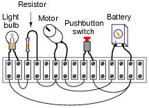
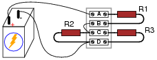
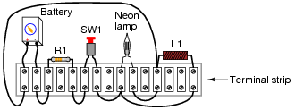
From observation of this circuit (with components attached to a "terminal strip"), draw an appropriate schematic diagram:
|
|
|
|
Notes:
This type of question is one that lends itself well to students drawing their answers on the board in front of class. The skill of transferring a real circuit into a cleanly-drawn schematic is one that some students struggle mightily with, but it is important. Those students will want to know what technique(s) may be used to make the transfer. Students who are more spatially adept will probably have a couple of different ways to approach a problem such as this. Allow them to explain to the rest of the class their technique(s) for tracing the real circuit's wiring into a schematic diagram.
Giving students the opportunity to teach their peers is a powerful instructional method, and should be encouraged at all times!
Question 4:
In a parallel circuit, certain general rules may be stated with regard to quantities of voltage, current, resistance, and power. Express these rules, using your own words:
Ïn a parallel circuit, voltage . . ."
Ïn a parallel circuit, current . . ."
Ïn a parallel circuit, resistance . . ."
Ïn a parallel circuit, power . . ."
For each of these rules, explain why it is true.
Ïn a parallel circuit, currents add to equal the total."
Ïn a parallel circuit, resistances diminish to equal the total."
Ïn a parallel circuit, power dissipations add to equal the total."
Notes:
Rules of series and parallel circuits are very important for students to comprehend. However, a trend I have noticed in many students is the habit of memorizing rather than understanding these rules. Students will work hard to memorize the rules without really comprehending why the rules are true, and therefore often fail to recall or apply the rules properly.
An illustrative technique I have found very useful is to have students create their own example circuits in which to test these rules. Simple series and parallel circuits pose little challenge to construct, and therefore serve as excellent learning tools. What could be better, or more authoritative, than learning principles of circuits from real experiments? This is known as primary research, and it constitutes the foundation of scientific inquiry. The greatest problem you will have as an instructor is encouraging your students to take the initiative to build these demonstration circuits on their own, because they are so used to having teachers simply tell them how things work. This is a shame, and it reflects poorly on the state of modern education.
Question 5:
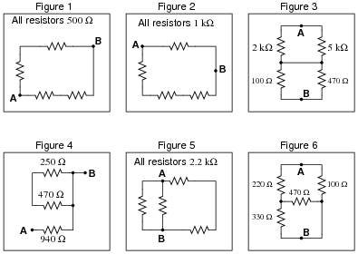
Calculate the resistance between points A and B (RAB) for the following resistor networks:
|
|
RAB = 500 W
Figure 2:
RAB = 750 W
Figure 3:
RAB = 1.511 kW
Figure 4:
RAB = 940 W
Figure 5:
RAB = 880 W
Figure 6:
RAB = 80.54 W
Notes:
Note that the circuit in figure 4 is a "trick:" two of the resistors contribute absolutely nothing to RAB! Be sure to discuss why this is with your students.
Discuss with your students how they approached each of these problems, and let the entire class participate in the reasoning process. The point of this question, like most of the questions in the Socratic Electronics project, is not merely to obtain the correct answers, but to stimulate understanding of how to solve problems such as these.
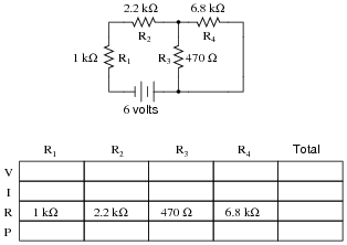
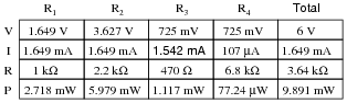
Question 6:
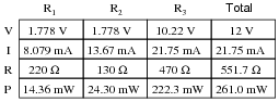
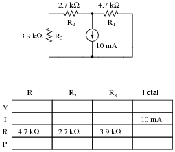
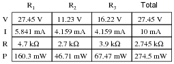
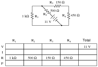
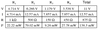
Complete the table of values for this circuit:
|
|
|
|
Notes:
Discuss with your students what a good procedure might be for calculating the unknown values in this problem, and also how they might check their work.
Students often have difficulty formulating a method of solution: determining what steps to take to get from the given conditions to a final answer. While it is helpful at first for you (the instructor) to show them, it is bad for you to show them too often, lest they stop thinking for themselves and merely follow your lead. A teaching technique I have found very helpful is to have students come up to the board (alone or in teams) in front of class to write their problem-solving strategies for all the others to see. They don't have to actually do the math, but rather outline the steps they would take, in the order they would take them.
By having students outline their problem-solving strategies, everyone gets an opportunity to see multiple methods of solution, and you (the instructor) get to see how (and if!) your students are thinking. An especially good point to emphasize in these öpen thinking" activities is how to check your work to see if any mistakes were made.
Question 7:
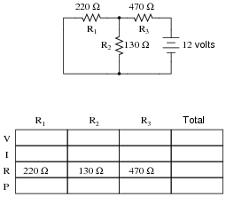
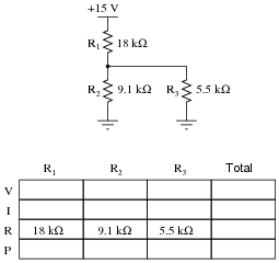
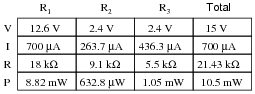
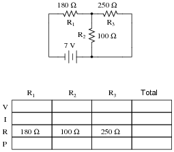
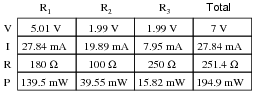
Complete the table of values for this circuit:
|
|
|
|
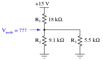
Follow-up question: how much voltage is present at the node (junction point) where R1, R2, and R3 all connect together, measured with reference to ground?
|
|
Notes:
A noteworthy feature of this circuit's schematic is how the power supply connections are shown. Unlike many of my schematic diagrams, I do not show a "battery" symbol here for a voltage source. Instead, I show power supply "rail" symbols (flat line and a ground symbol). Let your students know that this is very common symbolism in modern schematics, and that is merely saves having to draw lines to a voltage source symbol (as well as the source symbol itself).
Discuss with your students what a good procedure might be for calculating the unknown values in this problem, and also how they might check their work.
Students often have difficulty formulating a method of solution: determining what steps to take to get from the given conditions to a final answer. While it is helpful at first for you (the instructor) to show them, it is bad for you to show them too often, lest they stop thinking for themselves and merely follow your lead. A teaching technique I have found very helpful is to have students come up to the board (alone or in teams) in front of class to write their problem-solving strategies for all the others to see. They don't have to actually do the math, but rather outline the steps they would take, in the order they would take them.
By having students outline their problem-solving strategies, everyone gets an opportunity to see multiple methods of solution, and you (the instructor) get to see how (and if!) your students are thinking. An especially good point to emphasize in these öpen thinking" activities is how to check your work to see if any mistakes were made.
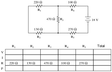
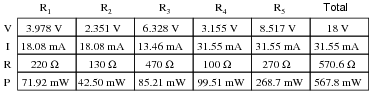
Question 8:
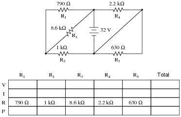
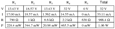
Complete the table of values for this circuit:
|
|
|
|
Notes:
Discuss with your students what a good procedure might be for calculating the unknown values in this problem, and also how they might check their work.
Students often have difficulty formulating a method of solution: determining what steps to take to get from the given conditions to a final answer. While it is helpful at first for you (the instructor) to show them, it is bad for you to show them too often, lest they stop thinking for themselves and merely follow your lead. A teaching technique I have found very helpful is to have students come up to the board (alone or in teams) in front of class to write their problem-solving strategies for all the others to see. They don't have to actually do the math, but rather outline the steps they would take, in the order they would take them.
By having students outline their problem-solving strategies, everyone gets an opportunity to see multiple methods of solution, and you (the instructor) get to see how (and if!) your students are thinking. An especially good point to emphasize in these öpen thinking" activities is how to check your work to see if any mistakes were made.
Question 9:
Complete the table of values for this circuit:
|
|
|
|
Challenge question: what circuit parameters will change if the diagonal wire in the right-hand side of the circuit is cut?
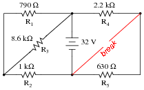
|
|
Notes:
Discuss with your students what a good procedure might be for calculating the unknown values in this problem, and also how they might check their work.
Question 10:
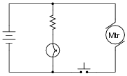
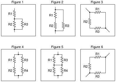
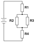
Identify which of these components are connected directly in series with each other, and which are connected directly in parallel with each other:
|
|
Assume that the open wire ends are connection points to a power source.
R2 in parallel with R3.
Figure 2:
R1 in series with R2.
Figure 3:
R2 in series with R3.
Figure 4:
R1 in series with R2; R3 in series with R4.
Figure 5:
R1 in parallel with R3; R2 in parallel with R4.
Figure 6:
R1 in series with R2.
Notes:
Work with your students to clearly identify rules by which series and parallel connections may be identified. This is extremely important for students to grasp if they are to be successful analyzing series-parallel networks of any kind. The most common problems I encounter as an electronics instructor with reference to series-parallel are invariably related to students' lack of ability to consistently distinguish series sub-networks and parallel sub-networks in series-parallel combination circuits.
Question 11:
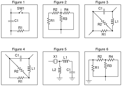
Identify which of these components are connected directly in series with each other, and which are connected directly in parallel with each other:
|
|
Assume that the open wire ends are connection points to a power source. In circuits where ground symbols appear, consider ground as the other side of the power source.
R1 in series with SW1.
Figure 2:
R1 in series with R2; R3 in parallel with R4.
Figure 3:
R1 parallel with R2.
Figure 4:
R1 parallel with R2.
Figure 5:
L1 in series with C1.
Figure 6:
R3 in parallel with R4.
Challenge question: if you compare figures 2 and 6, you see how merely changing the location(s) where the power supply connects to the network can alter the series/parallel relationships of the components. But, exactly what is it that is altered? If two components are in series with each other in one power source configuration, can that series relationship change by moving the power supply connection points? How about parallel connections? If two components are in parallel with each other, can that parallel relationship become altered merely by moving the points where the power source connects to the network? Explain.
Notes:
Work with your students to clearly identify rules by which series and parallel connections may be identified. This is extremely important for students to grasp if they are to be successful analyzing series-parallel networks of any kind. The most common problems I encounter as an electronics instructor with reference to series-parallel are invariably related to students' lack of ability to consistently distinguish series sub-networks and parallel sub-networks in series-parallel combination circuits.
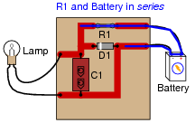
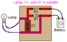
Question 12:
Identify which of these components are connected directly in series with each other, and which are connected directly in parallel with each other:

|
|
|
|
Connected directly in parallel: Lamp, C1, and D1
|
|
Notes:
Students must have a firm understanding of what constitutes ßeries" versus "parallel" in real circuits. Here is a place where some students will feel uncomfortable because the textbook definitions they memorized are easier said than applied. It is imperative that students have a strong working knowledge of terms, and do not simply memorize definitions.
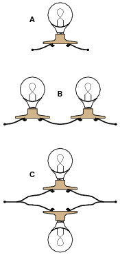
Question 13:
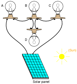
Rank these three light bulb assemblies according to their total electrical resistance (in order of least to greatest), assuming that each of the bulbs is the same type and rating:
|
|
Explain how you determined the relative resistances of these light bulb networks.
- �
- C (least total resistance)
- �
- A
- �
- B (greatest total resistance)
Notes:
I prefer to enter discussion on series and parallel circuits prior to introducing Ohm's Law. Conceptual analysis tends to be more difficult than numerical analysis in electric circuits, but is a skill worthwhile to build, especially for the sake of effective troubleshooting.
It is effective after conceptual (qualitative) analysis, though, to go through a numerical (quantitative) analysis of a circuit like this to prove that the concepts are correct, if the students are advanced enough at this point to do series-parallel resistance calculations.
Question 14:
Which components are guaranteed to share the exact same voltage by virtue of their connections with each other? Which components are guaranteed to share the exact same current by virtue of their connections with each other?
|
|
Notes:
Here, the important relations between voltage, current, and component connection patterns are explored. This serves to further define, in practical ways, what the terms ßeries" and "parallel" really mean.
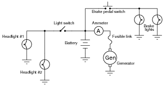
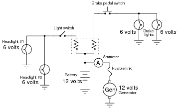
Question 15:
Which components in this partial automobile schematic diagram are guaranteed to share the exact same voltage by virtue of their connections with each other? Which components are guaranteed to share the exact same current by virtue of their connections with each other?
|
|
So long as the fusible link is not "blown," the generator and battery will share approximately the same voltage.
The ammeter, fusible link, and generator are all guaranteed to share the same current.
Notes:
Here, the important relations between voltage, current, and component connection patterns are explored. This serves to further define, in practical ways, what the terms ßeries" and "parallel" really mean.
This question also affords the opportunity of discussing what a "fusible link" is, and how it compares to fuses and circuit breakers as an overcurrent protection device.
Question 16:
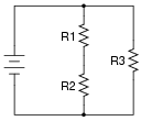
In this series-parallel circuit, resistors R1 and R2 are in series with each other, but resistor R3 is neither in series nor in parallel with either R1 or R2:
|
|
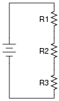
Normally, the first step in mathematically analyzing a circuit such as this is to determine the total circuit resistance. In other words, we need to calculate how much resistance the voltage source ßees" in the network formed by R1, R2, and R3. If the circuit were a simple series configuration, our task would be easy:
|
|
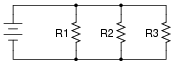
Likewise, if the circuit were a simple parallel configuration, we would have no difficulty at all calculating total resistance:
|
|
Due to the fact that our given circuit is neither purely series nor purely parallel, though, calculation of total resistance is not a simple one-step operation. However, there is a way we could simplify the circuit to something that is either simple series or simple parallel. Describe how that might be done, and demonstrate using numerical values for resistors R1, R2, and R3.
- �
- R1 = 3000 W
- �
- R2 = 2000 W
- �
- R3 = 5000 W
The total resistance in this case would be 2500 W. I'll let you figure out how to do this!
Hint: 2.5k is exactly one-half of 5k
Notes:
Figuring out how to calculate total resistance in a series-parallel network is an exercise in problem-solving. Students must determine how to convert a complex problem into multiple, simpler problems which they can then solve with the tools they have.
This sort of exercise is also helpful in getting students to think in terms of incremental problem-solving. Being able to take sections of a circuit and reduce them to equivalent component values so that the circuit becomes simpler and simpler to analyze is a very important skill in electronics.
Question 17:
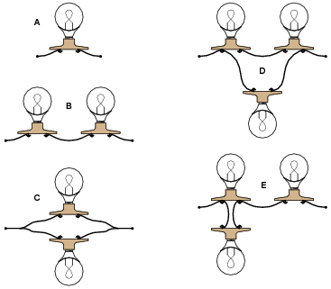
Rank these five light bulb assemblies according to their total electrical resistance (in order of least to greatest), assuming that each of the bulbs is the same type and rating:
|
|
Explain how you determined the relative resistances of these light bulb networks.
- �
- C (least total resistance)
- �
- D
- �
- A
- �
- E
- �
- B (greatest total resistance)
Notes:
I prefer to enter discussion on series and parallel circuits prior to introducing Ohm's Law. Conceptual analysis tends to be more difficult than numerical analysis in electric circuits, but is a skill worthwhile to build, especially for the sake of effective troubleshooting.
It is effective after conceptual (qualitative) analysis, though, to go through a numerical (quantitative) analysis of a circuit like this to prove that the concepts are correct, if the students are advanced enough at this point to do series-parallel resistance calculations.
Question 18:
Determine the amount of electrical resistance indicated by an ohmmeter connected between the following points in this circuit:
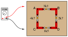
|
|
- �
- Between points A and B =
- �
- Between points A and C =
- �
- Between points C and D =
- �
- Between points D and B =
- �
- Between points B and C =
Explain whether or not it makes any sense to speak of a "total" resistance for this network.
- �
- Between points A and B = 2.41 kW
- �
- Between points A and C = 2.89 kW
- �
- Between points C and D = 1.32 kW
- �
- Between points D and B = 2.10 kW
- �
- Between points B and C = 2.75 kW
Notes:
The purpose of this question is to get students to realize that the resistance "looking into" different areas of a resistive network depends on what those areas are.
Question 19:
Calculate the amount of voltage dropped across resistor R2:
|
|
Also, note the direction of current through it and the polarity of the voltage drop across it.
Notes:
Discuss with your students how they obtained their answers for this question. The reasoning and procedures are far more important than the actual answer itself.
Students often have difficulty formulating a method of solution: determining what steps to take to get from the given conditions to a final answer. While it is helpful at first for you (the instructor) to show them, it is bad for you to show them too often, lest they stop thinking for themselves and merely follow your lead. A teaching technique I have found very helpful is to have students come up to the board (alone or in teams) in front of class to write their problem-solving strategies for all the others to see. They don't have to actually do the math, but rather outline the steps they would take, in the order they would take them.
By having students outline their problem-solving strategies, everyone gets an opportunity to see multiple methods of solution, and you (the instructor) get to see how (and if!) your students are thinking. An especially good point to emphasize in these öpen thinking" activities is how to check your work to see if any mistakes were made.
Question 20:
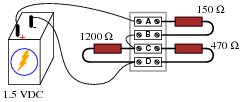
Antique American automobiles often used 6 volt electrical systems instead of the 12 volt components found in more modern cars and trucks. People who restore these old vehicles may have difficulty finding old 6-volt generators and batteries to replace the defective, original units. An easy solution is to update the vehicle's generator and battery with modern (12 volt) components, but then another problem arises.
A 12 volt generator and 12 volt battery will overpower the old 6 volt headlights, brake lights, and other electrical "loads" in the vehicle. A solution used by antique automobile restorers is to connect resistors between the 12-volt generator system and the 6-volt loads, like this:
|
|
Explain why this solution works, and also discuss some of the disadvantages of using resistors to adapt the new (12 volt) to the old (6 volt) components.
Notes:
Make sure your students understand the concept of a "load:" any electrical or electronic component that uses power from an electrical source. Usually, "loads" are the end-use components of a circuit: light bulbs, motors, solenoids, speakers, etc. In this case, the resistors could be considered loads as well as the light bulbs, but since the light bulbs are the only components performing useful work from the power source, it is customary to think of them when the word "load" is used, rather than the resistors.
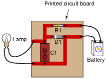
Question 21:
Draw a schematic diagram of this "breadboarded" circuit:
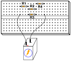
|
|
|
|
Notes:
If your students are not yet aware of how solderless breadboard holes are connected together, this is a good time to introduce them!
Question 22:
Think of a way to re-wire the electrical system of this old automobile (with 6-volt light bulbs) so as to not require resistors between the loads and the generator/battery portion of the circuit (operating at 12 volts each).

|
|
Follow-up question: there is a disadvantage of this strategy, though, and it concerns the safety of operating the automobile. Explain what this disadvantage is.
Notes:
This solution works only because the load sets are in pairs, and because 6 + 6 = 12. One benefit of this solution is greater efficiency, as there are no resistors in the circuit to "waste" power by dissipating it in the form of heat. However, there is a disadvantage to doing things this way, as indicated by the follow-up question. Discuss this disadvantage with your students, reinforcing the idea that the most efficient engineering solutions may not be the best when assessed from other perspectives, such as safety!
Question 23:
Calculate the voltage drops VAB, VBC, and VCD in the following circuit:
|
|
VBC = 0 V
VCD = 1.039 V
Follow-up question: explain why the voltage between points A and B (VAB) would increase if the 1200 W resistor were to fail shorted. Hint: imagine a "jumper" wire connected across that resistor to simulate a shorted failure.
Challenge question: explain how you can calculate these same answers without ever having to calculate total circuit current.
Notes:
Ask your students how they could tell VBC must be zero, just by examining the circuit (without doing any math). If some students experience difficulty answering this question on their own, have them translate the drawing into a proper schematic diagram.
Students often have difficulty formulating a method of solution: determining what steps to take to get from the given conditions to a final answer. While it is helpful at first for you (the instructor) to show them, it is bad for you to show them too often, lest they stop thinking for themselves and merely follow your lead. A teaching technique I have found very helpful is to have students come up to the board (alone or in teams) in front of class to write their problem-solving strategies for all the others to see. They don't have to actually do the math, but rather outline the steps they would take, in the order they would take them.
By having students outline their problem-solving strategies, everyone gets an opportunity to see multiple methods of solution, and you (the instructor) get to see how (and if!) your students are thinking. An especially good point to emphasize in these öpen thinking" activities is how to check your work to see if any mistakes were made.
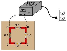
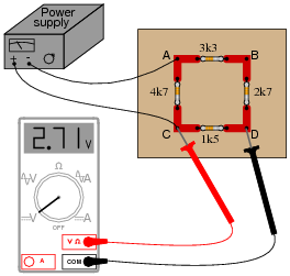
Question 24:
Calculate the voltage magnitude and polarity between points A and D in this circuit, assuming a power supply output voltage of 10.5 volts:
|
|
Also, calculate the total current output by the power supply as it energizes this resistor network.
Follow-up question: explain why the voltage across the 4.7 kW resistor would go to zero if the 1.5 kW resistor were to fail open.
Notes:
Though some students might not realize it at first, there is no series-parallel analysis necessary to obtain the voltage drop VAD.
Students often have difficulty formulating a method of solution: determining what steps to take to get from the given conditions to a final answer. While it is helpful at first for you (the instructor) to show them, it is bad for you to show them too often, lest they stop thinking for themselves and merely follow your lead. A teaching technique I have found very helpful is to have students come up to the board (alone or in teams) in front of class to write their problem-solving strategies for all the others to see. They don't have to actually do the math, but rather outline the steps they would take, in the order they would take them.
By having students outline their problem-solving strategies, everyone gets an opportunity to see multiple methods of solution, and you (the instructor) get to see how (and if!) your students are thinking. An especially good point to emphasize in these öpen thinking" activities is how to check your work to see if any mistakes were made.
As a follow-up to the follow-up question, ask your students what other resistor in this circuit would completely lose voltage given an open failure of the 1.5 kW resistor.
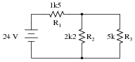
Question 25:
Calculate the power supply's output (total) current:
|
|
Follow-up question: explain why the voltage across the 1500 W resistor would remain unchanged if the 4700 W resistor were to fail open.
Challenge question: what crucial assumptions underlie the calculated figure for current shown here? In other words, what unknown quantities can affect the accuracy of our predicted current value?
Notes:
This is an interesting series-parallel circuit problem to solve, and it shows once again how a good understanding of circuit theory enables unmeasured variables to be inferred.
Students often have difficulty formulating a method of solution: determining what steps to take to get from the given conditions to a final answer. While it is helpful at first for you (the instructor) to show them, it is bad for you to show them too often, lest they stop thinking for themselves and merely follow your lead. A teaching technique I have found very helpful is to have students come up to the board (alone or in teams) in front of class to write their problem-solving strategies for all the others to see. They don't have to actually do the math, but rather outline the steps they would take, in the order they would take them.
By having students outline their problem-solving strategies, everyone gets an opportunity to see multiple methods of solution, and you (the instructor) get to see how (and if!) your students are thinking. An especially good point to emphasize in these öpen thinking" activities is how to check your work to see if any mistakes were made.
Question 26:
Complete the table of values for this circuit:
|
|
|
|
Notes:
Discuss with your students what a good procedure might be for calculating the unknown values in this problem, and also how they might check their work.
Students often have difficulty formulating a method of solution: determining what steps to take to get from the given conditions to a final answer. While it is helpful at first for you (the instructor) to show them, it is bad for you to show them too often, lest they stop thinking for themselves and merely follow your lead. A teaching technique I have found very helpful is to have students come up to the board (alone or in teams) in front of class to write their problem-solving strategies for all the others to see. They don't have to actually do the math, but rather outline the steps they would take, in the order they would take them.
By having students outline their problem-solving strategies, everyone gets an opportunity to see multiple methods of solution, and you (the instructor) get to see how (and if!) your students are thinking. An especially good point to emphasize in these öpen thinking" activities is how to check your work to see if any mistakes were made.
Question 27:
Complete the table of values for this circuit:
|
|
|
|
Notes:
Discuss with your students what a good procedure might be for calculating the unknown values in this problem, and also how they might check their work.
Question 28:
Complete the table of values for this circuit:
|
|
|
|
Notes:
Ask your students to identify components in this series-parallel circuit that are guaranteed to share the same voltage, and components that are guaranteed to share the same current, without reference to any calculations. This is a good exercise in identifying parallel and series interconnections, respectively.
Students often have difficulty formulating a method of solution: determining what steps to take to get from the given conditions to a final answer. While it is helpful at first for you (the instructor) to show them, it is bad for you to show them too often, lest they stop thinking for themselves and merely follow your lead. A teaching technique I have found very helpful is to have students come up to the board (alone or in teams) in front of class to write their problem-solving strategies for all the others to see. They don't have to actually do the math, but rather outline the steps they would take, in the order they would take them.
By having students outline their problem-solving strategies, everyone gets an opportunity to see multiple methods of solution, and you (the instructor) get to see how (and if!) your students are thinking. An especially good point to emphasize in these öpen thinking" activities is how to check your work to see if any mistakes were made.
Question 29:
What would happen to the voltage drops across each resistor in this circuit if resistor R1 were to fail open?

|
|
Notes:
In most DC circuit failure scenarios, the effects of open or short faults may be estimated or even precisely predicted without having to perform any mathematical calculations. Of course, you could calculate the effects by using extremely large values for open resistors and 0 for shorted resistors, but that would be an inefficient use of time!
Question 30:
What would happen to the voltage drops across each resistor in this circuit if either resistor R2 or R3 were to fail open?
|
|
Follow-up question: explain why it doesn't matter which resistor (R2 or R3) fails open - the qualitative results for voltage (voltage increasing or decreasing, but not by any specific amount) will be the same.
Notes:
I have found in teaching that many students loathe qualitative analysis, because they cannot let their calculators do the thinking for them. However, being able to judge whether a circuit parameter will increase, decrease, or remain the same after a component fault is an essential skill for proficient troubleshooting.
Question 31:
What will happen to each resistor's voltage and current in this circuit if resistor R1 fails open? Provide individual answers for each resistor, please.
|
|
- �
- VR1 will increase to full supply voltage, IR1 will decrease to zero
- �
- VR2 will decrease to zero, IR2 will decrease to zero
- �
- VR3 will decrease to zero, IR3 will decrease to zero
- �
- VR4 will decrease to zero, IR4 will decrease to zero
Follow-up question: note the order in which I list the qualitative effects of R2's shorted failure. Reading from the top of the list to the bottom reveals the sequence of my reasoning. Explain why I would come to the conclusions I did, in the order I did.
Notes:
I have found in teaching that many students loathe qualitative analysis, because they cannot let their calculators do the thinking for them. However, being able to judge whether a circuit parameter will increase, decrease, or remain the same after a component fault is an essential skill for proficient troubleshooting.
Question 32:
What will happen to each resistor's voltage and current in this circuit if resistor R2 fails shorted? Provide individual answers for each resistor, please.

|
|
- �
- VR2 will decrease to zero, IR2 will increase
- �
- VR1 will increase to full supply voltage, IR1 will increase
- �
- VR3 will decrease to zero, IR3 will decrease to zero
- �
- VR4 will decrease to zero, IR4 will decrease to zero
Follow-up question: note the order in which I list the qualitative effects of R2's shorted failure. Reading from the top of the list to the bottom reveals the sequence of my reasoning. Explain why I would come to the conclusions I did, in the order I did.
Notes:
I have found in teaching that many students loathe qualitative analysis, because they cannot let their calculators do the thinking for them. However, being able to judge whether a circuit parameter will increase, decrease, or remain the same after a component fault is an essential skill for proficient troubleshooting.
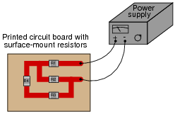
Question 33:
What will happen to each resistor's voltage in this circuit if resistor R4 fails shorted? Provide individual answers for each resistor, please.

|
|
Also, comment on the practical likelihood of a resistor failing shorted, as opposed to failing open.
- �
- VR4 will decrease to zero
- �
- VR1 will increase
- �
- VR2 will decrease
- �
- VR3 will increase
Follow-up question: resistors are actually far less likely to fail shorted as they are to fail open. However, this does not mean something else on a circuit board cannot go wrong to make it appear as though a resistor failed shorted! One example of such a fault is called a solder bridge. Explain what this is, any why it could produce the same effect as a resistor failing shorted.
Notes:
I have found in teaching that many students loathe qualitative analysis, because they cannot let their calculators do the thinking for them. However, being able to judge whether a circuit parameter will increase, decrease, or remain the same after a component fault is an essential skill for proficient troubleshooting.
Question 34:
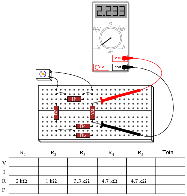
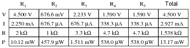
A student built this resistor circuit on a solderless breadboard, but made a mistake positioning resistor R3. It should be located one hole to the left instead of where it is right now:
|
|
Determine what the voltage drop will be across each resistor, in this faulty configuration, assuming that the battery outputs 9 volts.
- �
- R1 = 2 k W VR1 =
- �
- R2 = 1 k W VR2 =
- �
- R3 = 3.3 k W VR3 =
- �
- R4 = 4.7 k W VR4 =
- �
- R5 = 4.7 k W VR5 =
Notes:
Tell your students that the fault shown in this question is quite typical. The hole spacings on solderless breadboards are small enough that it is surprisingly easy to mis-locate a component in the manner shown.
Point out to your students (if they haven't already noticed) that no calculations are necessary to answer this question! It may be answered through simple, qualitative analysis alone.
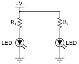
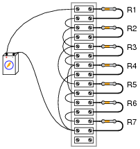
Question 35:
Suppose you were designing a circuit that required two LEDs for "power on" indication. The power supply voltage is 15 volts, and each LED is rated at 1.6 volts and 20 mA. Calculate the dropping resistor sizes and power ratings:
|
|
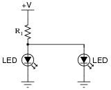
After doing this, a co-worker looks at your circuit and suggests a modification. Why not use a single dropping resistor for both LEDs, economizing the number of components necessary?
|
|
Re-calculate the dropping resistor ratings (resistance and power) for the new design.
With one resistor: R1 = 335 W, rated for at least 0.536 watts (1 watt would be a practical rating).
Follow-up question: if there were no perfectly sized resistors sized to choose from (which there most likely will not be!), would it be safer to choose a higher-value resistor or a lower-value resistor for these applications? For example, if you needed 670 W but the closest options on hand were 680 W and 500 W, which resistance value would you select? Explain your answer.
Notes:
If students are not yet familiar with the "+V" symbol used to denote the positive power supply connection in this schematic, let them know that this is a very common practice in electronic notation, just as it is common to use the ground symbol as a power supply connection symbol.
The follow-up question is a very practical one, for it is seldom that you have the exact components on-hand to match the requirements of a circuit you are building. It is important to understand which way is safer to err (too large or too small) when doing äs-built" design work.
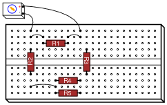
Question 36:
Calculate all voltages and currents in this circuit:
|
|
The battery voltage is 15 volts, and the resistor values are as follows:
- R1 = 1 kW
- R2 = 3.3 kW
- R3 = 4.7 kW
- R4 = 2.5 kW
- R5 = 10 kW
- R6 = 1.5 kW
- R7 = 500 W
| R1 = 1 kW | ER1 = 4.016 V | IR1 = 4.016 mA |
| R2 = 3.3 kW | ER2 = 6.522 V | IR2 = 1.976 mA |
| R3 = 4.7 kW | ER3 = 6.522 V | IR3 = 1.388 mA |
| R4 = 2.5 kW | ER4 = 4.462 V | IR4 = 1.785 mA |
| R5 = 10 kW | ER5 = 6.522 V | IR5 = 652 mA |
| R6 = 1.5 kW | ER6 = 3.347 V | IR6 = 2.231 mA |
| R7 = 500 W | ER7 = 1.116 V | IR7 = 2.231 mA |
Notes:
Your students will benefit greatly from having a clean schematic diagram to work off of. However, do not supply this for them! Let them figure out how to derive a schematic diagram from the illustrated circuit.
Students often have difficulty formulating a method of solution: determining what steps to take to get from the given conditions to a final answer. While it is helpful at first for you (the instructor) to show them, it is bad for you to show them too often, lest they stop thinking for themselves and merely follow your lead. A teaching technique I have found very helpful is to have students come up to the board (alone or in teams) in front of class to write their problem-solving strategies for all the others to see. They don't have to actually do the math, but rather outline the steps they would take, in the order they would take them.
By having students outline their problem-solving strategies, everyone gets an opportunity to see multiple methods of solution, and you (the instructor) get to see how (and if!) your students are thinking. An especially good point to emphasize in these öpen thinking" activities is how to check your work to see if any mistakes were made.
Question 37:
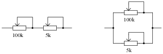
Examine these two variable-resistance (rheostat) networks, each one with a large-range potentiometer and a small-range potentiometer:
|
|
For each network, determine which pot is the coarse adjustment and which pot is the fine adjustment for total resistance.
100k = Coarse adjustment ; 5k = Fine adjustment
Parallel network
5k = Coarse adjustment ; 100k = Fine adjustment
Notes:
The purpose of this question is for students to identify the dominant resistance values in series versus parallel circuits. Remind your students if necessary that Rtotal > Rn for series and Rtotal < Rn for parallel (where Rn represents any particular resistor in the network).
Question 38:
Identify which of these components are connected directly in series with each other, and which are connected directly in parallel with each other:
|
|
Notes:
Students must have a firm understanding of what constitutes ßeries" versus "parallel" in real circuits. Here is a place where some students will feel uncomfortable because the textbook definitions they memorized are easier said than applied. It is imperative that students have a strong working knowledge of terms, and do not simply memorize definitions.
Question 39:
Complete the table of values for this circuit:
|
|
|
|
Notes:
Discuss with your students what a good procedure might be for calculating the unknown values in this problem, and also how they might check their work.
Students often have difficulty formulating a method of solution: determining what steps to take to get from the given conditions to a final answer. While it is helpful at first for you (the instructor) to show them, it is bad for you to show them too often, lest they stop thinking for themselves and merely follow your lead. A teaching technique I have found very helpful is to have students come up to the board (alone or in teams) in front of class to write their problem-solving strategies for all the others to see. They don't have to actually do the math, but rather outline the steps they would take, in the order they would take them.
By having students outline their problem-solving strategies, everyone gets an opportunity to see multiple methods of solution, and you (the instructor) get to see how (and if!) your students are thinking. An especially good point to emphasize in these öpen thinking" activities is how to check your work to see if any mistakes were made.
Question 40:
Complete the table of values for this circuit:
|
|
|
|
Notes:
Discuss with your students what a good procedure might be for calculating the unknown values in this problem, and also how they might check their work.
Students often have difficulty formulating a method of solution: determining what steps to take to get from the given conditions to a final answer. While it is helpful at first for you (the instructor) to show them, it is bad for you to show them too often, lest they stop thinking for themselves and merely follow your lead. A teaching technique I have found very helpful is to have students come up to the board (alone or in teams) in front of class to write their problem-solving strategies for all the others to see. They don't have to actually do the math, but rather outline the steps they would take, in the order they would take them.
By having students outline their problem-solving strategies, everyone gets an opportunity to see multiple methods of solution, and you (the instructor) get to see how (and if!) your students are thinking. An especially good point to emphasize in these öpen thinking" activities is how to check your work to see if any mistakes were made.
Question 41:
Determine which light bulb(s) will glow brightly, and which light bulb(s) will glow dimly (assuming all light bulbs are identical).
|
|
Follow-up question: explain why bulbs Ä" and "C" will become dimmer (less bright) if the filament in bulb "D" fails open.
Notes:
This question provides an opportunity to discuss current in series- versus parallel-connected components. The follow-up question challenges students to qualitatively analyze the circuit.