DC generator theory
Question 1:
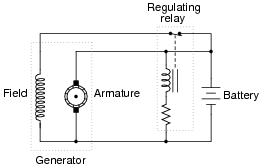
Generators used in battery-charging systems must be regulated so as to not overcharge the battery(ies) they are connected to. Here is a crude, relay-based voltage regulator for a DC generator:
|
|
Simple electromechanical relay circuits such as this one were very common in automotive electrical systems during the 1950's, 1960's, and 1970's. The fundamental principle upon which their operation is based is called negative feedback: where a system takes action to oppose any change in a certain variable. In this case, the variable is generator output voltage. Explain how the relay works to prevent the generator from overcharging the battery with excessive voltage.
Challenge question: what would we have to change in this circuit to alter the generator's voltage regulation set-point (the "target" voltage at which the generator's output is supposed to be regulated)?
Notes:
The circuit drawn here is very similar to real generator regulator circuits used in American automobiles before the advent of inexpensive, reliable semiconductor circuits. I show it here not just for historical background, but also to demonstrate how relatively crude circuits are still able to perform certain tasks reasonably well.
"Negative feedback" is one of the fundamental principles of electronics and electrical engineering. A simple system like this provides a good way to gently introduce students to this vital concept.
Question 2:
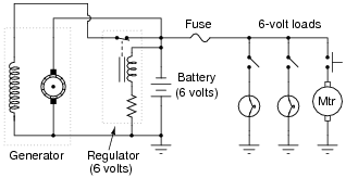
A mechanic has an idea for upgrading the electrical system in an automobile originally designed for 6 volt operation. He wants to upgrade the 6 volt headlights, starter motor, battery, etc, to 12 volts, but wishes to retain the original 6-volt generator and regulator. Shown here is the original 6-volt electrical system:
|
|
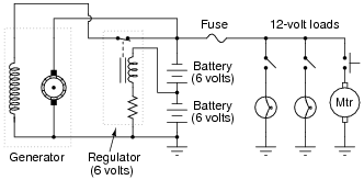
The mechanic's plan is to replace all the 6-volt loads with 12-volt loads, and use two 6-volt batteries connected in series, with the original (6-volt) regulator sensing voltage across only one of those batteries:
|
|
Explain how this system is supposed to work. Do you think the mechanic's plan is practical, or are there any problems with it?
Challenge question: identify factors that may prevent the generator from outputting enough voltage with the regulator connected as shown in the last diagram.
Notes:
In this question, we see a foreshadowing of op-amp theory, with the regulator's negative feedback applied to what is essentially a voltage divider (two equal-voltage batteries being charged by the generator). The regulator circuit senses only 6 volts, but the generator outputs 12 volts.
Fundamentally, the focus of this question is negative feedback and one of its many practical applications in electrical engineering. The depth to which you discuss this concept will vary according to the students' readiness, but it is something you should at least mention during discussion on this question.
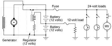
This idea actually came from one of the readers of my textbook series Lessons In Electric Circuits. He was trying to upgrade a vehicle from 12 volts to 24 volts, but the principle is the same. An important difference in his plan was that he was still planning on having some 12-volt loads in the vehicle (dashboard gauges, starter solenoid, etc.), with the full 24 volts supplying only the high-power loads (such as the starter motor itself):
|
|
As a challenge for your students, ask them how well they think this system would work. It is a bit more complex than the system shown in the question, due to the two different load banks.
Question 3:
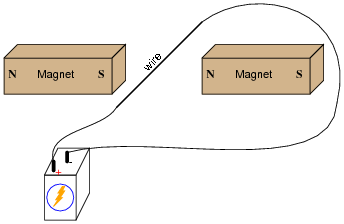
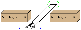
If an electric current is passed through this wire, which direction will the wire be pushed (by the interaction of the magnetic fields)?
|
|
Is this an example of an electric motor or an electric generator?
Notes:
A visual aid to understanding the interaction of the two magnetic fields is a diagram showing the lines of flux emanating from the permanent magnets, against the circular lines of flux around the wire. Ask those students who came across similar illustrations in their research to draw a picture of this on the board in front of the class, for those who have not seen it.
Question 4:
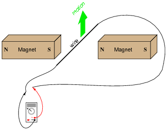
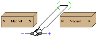
If this wire (between the magnet poles) is moved in an upward direction, what polarity of voltage will the meter indicate?
|
|
Describe the factors influencing the magnitude of the voltage induced by motion, and determine whether this is an example of an electric motor or an electric generator.
Notes:
Ask your students to explain their answers regarding factors that influence voltage magnitude. Where did they obtain their information? Are there any mathematical formulae relating these factors to induced voltage?
Question 5:
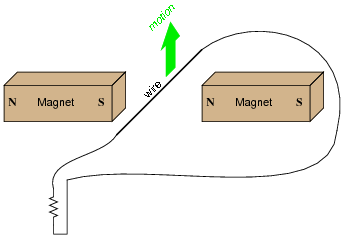
If this wire (between the magnet poles) is moved in an upward direction, and the wire ends are connected to a resistive load, which way will current go through the wire?
|
|
We know that current moving through a wire will create a magnetic field, and that this magnetic field will produce a reaction force against the static magnetic fields coming from the two permanent magnets. Which direction will this reaction force push the current-carrying wire? How does the direction of this force relate to the direction of the wire's motion? Does this phenomenon relate to any principle of electromagnetism you've learned so far?
Follow-up question: What does this phenomenon indicate to us about the ease of moving a generator mechanism under load, versus unloaded? What effect does placing an electrical load on the output terminals of a generator have on the mechanical effort needed to turn the generator?
Notes:
If you happen to have a large, permanent magnet DC motor available in your classroom, you may easily demonstrate this principle for your students. Just have them spin the shaft of the motor (generator) with their hands, with the power terminals open versus shorted together. Your students will notice a huge difference in the ease of turning between these two states.
After your students have had the opportunity to discuss this phenomenon and/or experience it themselves, ask them why electromechanical meter movement manufacturers usually ship meters with a shorting wire connecting the two meter terminals together. In what way does a PMMC meter movement resemble an electric generator? How does shorting the terminals together help to protect against damage from physical vibration during shipping?
Ask your students to describe what factors influence the magnitude of this reaction force.
Question 6:
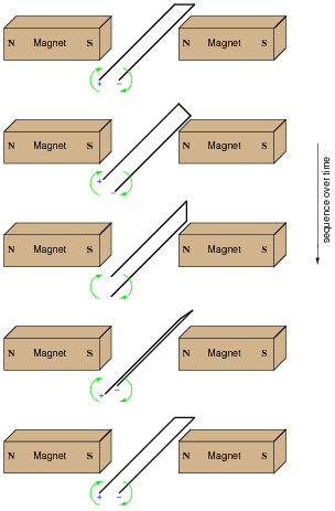
Determine the polarity of induced voltage between the ends of this wire loop, as it is rotated between the two magnets:

|
|
|
|
Challenge question: if a resistor were connected between the ends of this wire loop, would it ßee" direct current (DC), or alternating current (AC)?
Notes:
Note that the two wire ends switch polarity as the loop rotates. Ask your students to explain why the polarities are as they are.
Question 7:
If the ends of a wire loop are attached to two half-circular metal strips, arranged so that the two strips almost form a complete circle, and those strips are contacted by two "brushes" which connect to opposite poles of a battery, what polarity of voltage will be measured as the loop is rotated counter-clockwise?
|
|
|
|
Follow-up question: does the polarity measured at the two carbon brushes ever reverse? Or, to phrase the question another way, if a resistor were connected between the two brush contacts, would it ßee" direct current (DC) or alternating current (AC)? Explain your answer.
Notes:
Ask your students what the two half-circle metal strips are called, in electric motor/generator terminology.
Question 8:
How does Faraday's Law of electromagnetic induction relate to the voltage output of a DC generator? According to Faraday's Law, what factors can we alter to increase the voltage output by a DC generator?
Notes:
Ask your students to write the equation for Faraday's Law on the whiteboard, and then analyze it in a qualitative sense (with variables increasing or decreasing in value) to validate the answers.
The first answer to this question (increase [(df)/dt]) has been left purposefully vague, in order to make students think. What, specifically, must be changed in order to increase this rate-of-change over time? Which real-world variables are changeable after the generator has been manufactured, and which are not?
Question 9:
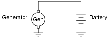
DC generators will act as DC motors if connected to a DC power source and not spun at a sufficient speed. This is a problem in DC power systems, as the generator will act as a load, drawing energy from the battery, when the engine or other "prime mover" device stops moving. This simple generator/battery circuit, for example, would not be practical for this reason:
|
|
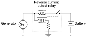
Back in the days when automobiles used DC generators to charge their batteries, a special relay called the reverse current cutout relay was necessary to prevent battery discharge through the generator whenever the engine was shut off:
|
|
When the generator is spun fast enough, it generates enough voltage to energize the shunt coil with enough current to close the relay contact. This connects the generator with the battery, and charging current flows through the series coil, creating even more magnetic attraction to hold the relay contact closed. If the battery reaches a full charge and does not draw any more charging current from the generator, the relay will still remain closed because the shunt coil is still energized.
However, the relay contact will open if the generator ever begins to act as a load to the battery, drawing any current from it. Explain why this happens.
Notes:
A "reverse current cutout" relay ingeniously exploits reversible magnetic polarities to close or open a contact under the proper conditions. Although DC generators are no longer used in the majority of automobile electrical systems (AC alternators using bridge rectifiers to convert AC to DC are used instead, with the rectifier circuit naturally preventing reverse current), this application provides an excellent opportunity to explore an application of relay technology in the context of generator control.
Question 10:
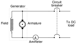
A shunt-wound generator has an electromagnet "field" winding providing the stationary magnetic field in which the armature rotates:

|
|
Like all electromagnets, the magnetic field strength produced is in direct proportion to the amount of current through the wire coil. But when the generator is sitting still, its output voltage is zero, and therefore there will be no current through the field winding to energize it and produce a magnetic field for the armature to rotate through. This causes a problem, since the armature will not have any voltage induced in its windings until it is rotating and it has a stationary magnetic field from the field winding to rotate through.
It seems like we have a catch-22 situation here: the generator cannot output a voltage until its field winding is energized, but its field winding will not be energized until the generator (armature) outputs some voltage. How can this generator ever begin to output voltage, given this predicament?
Challenge question: what we could do if the generator's field poles ever totally lost their residual magnetism? How could the generator ever be started?
Notes:
Back in the days when generators were common in automotive electrical systems, this used to be a fairly common problem. However, generators could be "flashed" so as to re-establish this residual magnetic field once again.
Question 11:
In a shunt-wound DC generator, the output voltage is determined by the rotational speed of the armature and the density of the stationary magnetic field flux. For a given armature speed, what prevents the output voltage from "running away" to infinite levels, since the output voltage energizes the field winding, which leads to greater field flux, which leads to greater output voltage, which leads to greater field flux, which leads to . . . ?
|
|
Obviously, there must be some inherent limit to this otherwise vicious cycle. Otherwise, the output voltage of a shunt-wound DC generator would be completely unstable.
Notes:
This question provides a great opportunity to review the concept of magnetic ßaturation," as well as introduce the engineering concept of positive feedback.
Question 12:
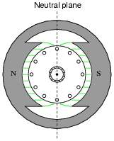
With regard to a DC electric generator, what is the neutral plane? Why is this important?
|
|
Notes:
Ask your students why the "neutral plane" is an important aspect of a DC generator or motor's geometry. What relation does the neutral plane have with regard to brush positioning? At what point in the armature's rotation do we want to have the brushes break contact with one commutator bar and make contact with another: when the coil primary to that commutator segment is outputting maximum voltage, or minimum voltage?
Question 13:
Suppose a generator is mechanically coupled to an internal combustion engine in an automobile, for the purpose of charging the starting battery. In order that the battery not be over-charged by the generator, there must be some way of controlling the generator's output voltage over a wide range of engine speeds.
How is this regulation of generator output voltage typically achieved? What variable within the generator may be most easily adjusted to maintain a nearly constant output voltage? Express your answer in relation to Faraday's Law of electromagnetic induction.
Notes:
Although adjustable field winding excitation is the most popular form of generator output voltage control, it is not the only means. Challenge your students with inventing other means of charge control for the battery in this automotive electrical system, besides field winding excitation control. What else can we do to the generator, or to the circuit it is within, to achieve charge control for the battery?
Question 14:
In most high-power DC generator and motor designs, the wire used to make the field winding is much thinner gauge than the wire used to make the armature winding. This indicates the relative magnitude of current through these respective windings, with the armature coils conducting much more current than the field coils.
That the armature conducts more current than the field is no small matter, because all current through the armature must be conducted through the brushes and commutator bars. The more current these components have to carry, the shorter their life, all other factors being equal.
Couldn't the generator be re-designed so that the field conducted most of the current, with the armature only conducting a small amount? This way, the brushes and commutator bars would only have to carry a fraction of their normal current, making them less expensive and longer-lived. Explain why this is impossible to do.
Hint: consider the design of a permanent-magnet generator.
Notes:
Being that brush and commutator wear is the main reason AC motors and generators are favored over DC, any idea that may potentially reduce the "wear and tear" on DC motor or generator brushes is worth considering. However, the idea proposed in this question will never work. This is not necessarily an easy question to answer, as it tests the students' comprehension of generator theory. The hint given in the question ("consider a permanent-magnet generator") is intended to force students to simplify the problem, by considering a working generator design that only has one winding (the armature). By simplifying the problem in this way, students should see that the armature winding has to carry the bulk of the current in a DC generator.