DC motor control circuits
Question 1:
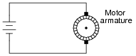
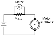
How is it possible to electrically measure the torque output by a permanent-magnet DC motor? Hint: it is very simple, and for large electric motors it involves the use of a shunt resistor. Modify this circuit diagram to include a meter that provides indirect indication of motor torque:
|
|
|
|
Notes:
If some of your students think the "V" symbol in the meter means it is measuring motor voltage, they need to review the purpose and function of a shunt resistor!
This method of measuring motor torque is accurate, so long as the motor is in good condition. Ask your students what they think the meter would indicate if the motor began to develop a low-resistance fault due to carbon dust buildup from the brushes shorting some of the armature current. Would the meter indicate falsely low, falsely high, or would it still accurately register motor torque?
Question 2:
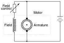
What will happen to the stall torque of this DC motor if the "field control" resistor value is suddenly decreased? Explain your answer.
|
|
Notes:
Your students will most likely have to research the meaning of the phrase ßtall torque" before they can answer this question. That is a good thing, though! Begin your discussion on this question with a survey of definitions found for this phrase.
Question 3:
What will happen to the counter-EMF of this DC motor if the "field control" resistor value is suddenly decreased (while it is running)?

|
|
What effect will this change in field excitation do to the operating speed of the motor?
Notes:
In case your students have never heard the word ëxcitation" used in this context, it would be a good idea to explain it now. The electrical power used to energize a circuit in which a particular output is expected is sometimes referred to as ëxcitation." Bridge circuit power supplies are another example of an ëxcitation" source.
This is a very important, but often misunderstood, aspect of DC motor control. While it seems paradoxical that an increase in power applied to the field winding will cause the motor to slow down, it is indeed true. Ask your students to explain what will happen to the motor speed if the field excitation is weakened.
Question 4:
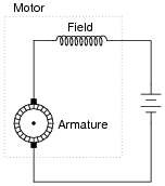
Series-wound DC motors have very different operating characteristics than either shunt-wound or permanent magnet DC motors. Describe what happens in a series-wound motor when a mechanical load is placed on the motor, causing it to slow down and the counter-EMF to decrease:
|
|
Contrast this behavior against that of a permanent magnet DC motor under the same conditions (increased mechanical load, causing counter-EMF to decrease).
Notes:
Ask your students to contrast this motor behavior against that of a permanent magnet or shunt-wound motor. What happens to the stationary magnetic field strengths in those motor types when mechanically loaded? Ask your students what applications might be best for series motors, and what applications might be best for shunt or permanent magnet motors.
Question 5:
Describe what a compound-wound DC electric motor is, and how it compares with the other motor types you've learned about so far.
Notes:
Ask your students to draw the schematic diagram of a compound DC motor, showing both field winding sets. Also, ask them if there is any substantial difference between the construction of the two field windings (shunt versus series). One is definitely different from the other, and with good reason!
Question 6:
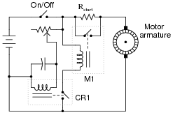
This motor-start circuit reduces the amount of ïnrush" current when starting by inserting a resistance in series with the motor for a few seconds, then removing that resistance after the time delay to allow full speed operation. A time-delay relay provides the reduced-speed control.
|
|
The relay labeled "M1" is a large "contactor" designed to shunt the motor's current around the start-up resistor. It requires at least a few amps of current through its coil to energize.
The relay labeled "CR1" is a much smaller "control relay," and its turn-on time is controlled by the charging of an electrolytic capacitor.
What could be adjusted in this circuit to make it switch to full-speed operation sooner after start-up?
Challenge question: what else could be changed in this circuit to provide a shorter "reduced speed" time period?
Notes:
This general principle is useful for the start-up of many different electric motors (including most AC motors). Circuits like this are sometimes referred to as soft start controls.
Ask your students to describe which way the potentiometer wiper needs to be moved in order to accommodate the resistance change.
Question 7:
There is more than one way to electrically "brake" (slow down) an electric motor. Three methods in common use are:
- �
- Dynamic braking
- �
- Regenerative braking
- �
- Plugging
Describe how each of these methods work.
Notes:
All three methods of motor braking are used in industry, each with its own benefits. Discuss the relative merits of each method with your students, with regard to simplicity, braking power, power consumption, etc.
Be sure to discuss the advantages and disadvantages of electrical braking over mechanical braking. What advantage(s) does electrical braking (using the motor as a brake) have over mechanical braking (using a separate brake mechanism attached to the motor shaft)? Which type of braking do you think might be more reliable?
Question 8:
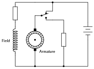
Identify the method of electrical braking used in this motor control circuit:
|
|
Notes:
It is apparent from the schematic diagram that the motor's field winding continues to receive power when the switch is in the "brake" position. Ask the students why this is necessary for dynamic braking to work. Ask them what would happen if the field winding were de-energized as well as the armature, as the switch moved to the "brake" position.
Question 9:
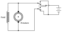
Suppose someone wires a DPDT switch to an electric motor like this, hoping to achieve forward/reverse control:
|
|
Unfortunately, this switch arrangement will not reverse the motor!
Explain why the motor will not reverse, and determine a correction to the circuit that will allow the switch to function as a forward/reverse control.
Follow-up question: what does this fact tell us about the motor's ability to operate on alternating current (AC)?
Notes:
There is more than one solution for the reversing problem. Discuss your students' solutions, and encourage the submission of multiple ideas! One thing you might want to mention is that the field winding of a shunt-wound DC motor like this typically draws far less current than the armature winding (especially under full load). Ask your students how this fact might influence their decision on how to re-design the switch circuit.