Rectifying diodes
Question 1:
| Don't just sit there! Build something!! |
Learning to mathematically analyze circuits requires much study and practice. Typically, students practice by working through lots of sample problems and checking their answers against those provided by the textbook or the instructor. While this is good, there is a much better way.
You will learn much more by actually building and analyzing real circuits, letting your test equipment provide the änswers" instead of a book or another person. For successful circuit-building exercises, follow these steps:
- 1.
- Carefully measure and record all component values prior to circuit construction, choosing resistor values high enough to make damage to any active components unlikely.
- 2.
- Draw the schematic diagram for the circuit to be analyzed.
- 3.
- Carefully build this circuit on a breadboard or other convenient medium.
- 4.
- Check the accuracy of the circuit's construction, following each wire to each connection point, and verifying these elements one-by-one on the diagram.
- 5.
- Mathematically analyze the circuit, solving for all voltage and current values.
- 6.
- Carefully measure all voltages and currents, to verify the accuracy of your analysis.
- 7.
- If there are any substantial errors (greater than a few percent), carefully check your circuit's construction against the diagram, then carefully re-calculate the values and re-measure.
When students are first learning about semiconductor devices, and are most likely to damage them by making improper connections in their circuits, I recommend they experiment with large, high-wattage components (1N4001 rectifying diodes, TO-220 or TO-3 case power transistors, etc.), and using dry-cell battery power sources rather than a benchtop power supply. This decreases the likelihood of component damage.
As usual, avoid very high and very low resistor values, to avoid measurement errors caused by meter "loading" (on the high end) and to avoid transistor burnout (on the low end). I recommend resistors between 1 kW and 100 kW.
One way you can save time and reduce the possibility of error is to begin with a very simple circuit and incrementally add components to increase its complexity after each analysis, rather than building a whole new circuit for each practice problem. Another time-saving technique is to re-use the same components in a variety of different circuit configurations. This way, you won't have to measure any component's value more than once.
Notes:
It has been my experience that students require much practice with circuit analysis to become proficient. To this end, instructors usually provide their students with lots of practice problems to work through, and provide answers for students to check their work against. While this approach makes students proficient in circuit theory, it fails to fully educate them.
Students don't just need mathematical practice. They also need real, hands-on practice building circuits and using test equipment. So, I suggest the following alternative approach: students should build their own "practice problems" with real components, and try to mathematically predict the various voltage and current values. This way, the mathematical theory "comes alive," and students gain practical proficiency they wouldn't gain merely by solving equations.
Another reason for following this method of practice is to teach students scientific method: the process of testing a hypothesis (in this case, mathematical predictions) by performing a real experiment. Students will also develop real troubleshooting skills as they occasionally make circuit construction errors.
Spend a few moments of time with your class to review some of the "rules" for building circuits before they begin. Discuss these issues with your students in the same Socratic manner you would normally discuss the worksheet questions, rather than simply telling them what they should and should not do. I never cease to be amazed at how poorly students grasp instructions when presented in a typical lecture (instructor monologue) format!
A note to those instructors who may complain about the "wasted" time required to have students build real circuits instead of just mathematically analyzing theoretical circuits:
What is the purpose of students taking your course?
If your students will be working with real circuits, then they should learn on real circuits whenever possible. If your goal is to educate theoretical physicists, then stick with abstract analysis, by all means! But most of us plan for our students to do something in the real world with the education we give them. The "wasted" time spent building real circuits will pay huge dividends when it comes time for them to apply their knowledge to practical problems.
Furthermore, having students build their own practice problems teaches them how to perform primary research, thus empowering them to continue their electrical/electronics education autonomously.
In most sciences, realistic experiments are much more difficult and expensive to set up than electrical circuits. Nuclear physics, biology, geology, and chemistry professors would just love to be able to have their students apply advanced mathematics to real experiments posing no safety hazard and costing less than a textbook. They can't, but you can. Exploit the convenience inherent to your science, and get those students of yours practicing their math on lots of real circuits!
Question 2:
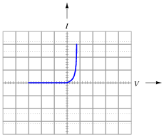
When plotted on a curve tracer, the characteristic curve for a normal PN junction rectifying diode looks something like this:

|
|
Label each axis (horizontal and vertical) of the curve tracer graph, then determine whether the diode behaves more like a voltage source or more like a current source (i.e. does it try to maintain constant voltage or does it try to maintain constant current?) when it is conducting current.
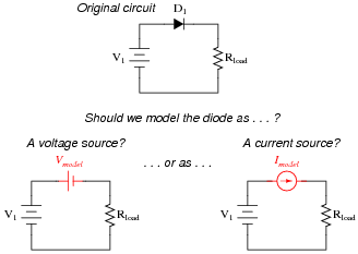
Models are very useful because they simplify circuit approximations. For example, we can analyze this diode circuit quite easily if we substitute an electrical source in place of the diode:
|
|
The only question here is, which substitution makes the most sense? Based on the diode's characteristic curve behavior, should we substitute a voltage source or a current source in place of it? Assuming this is a 1N4001 rectifying diode, what is the value we should use for the substituting source?
|
|
This behavior is similar to that of a voltage source once it is forward-biased and conducting current.
Follow-up question: quite obviously, diodes do not behave exactly as voltage sources. You cannot power anything off of a diode, for instance! Identify some of the limitations inherent to modeling diodes as voltage sources. Are there any instances you can think of where such a model could be misleading?
Notes:
Modeling nonlinear semiconductor components in terms of linear, idealized passive components is a time-honored "trick" used to simplify circuit analysis. Like all "tricks" and analogies, this one has definite limitations. The follow-up question's hint practically gives away examples of where such a model could be misleading!
Question 3:
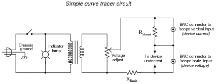
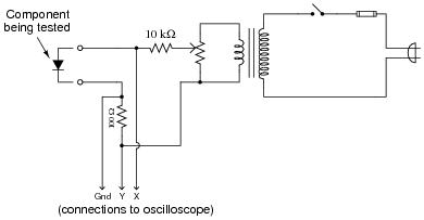
The following schematic diagram is of a simple curve tracer circuit, used to plot the current/voltage characteristics of different electronic components on an oscilloscope screen:
|
|
The way it works is by applying an AC voltage across the terminals of the device under test, outputting two different voltage signals to the oscilloscope. One signal, driving the horizontal axis of the oscilloscope, represents the voltage across the two terminals of the device. The other signal, driving the vertical axis of the oscilloscope, is the voltage dropped across the shunt resistor, representing current through the device. With the oscilloscope set for "X-Y" mode, the electron beam traces the device's characteristic curve.
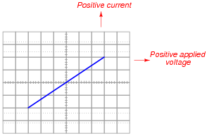
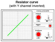
For example, a simple resistor would generate this oscilloscope display:
|
|
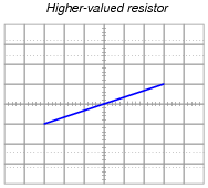
A resistor of greater value (more ohms of resistance) would generate a characteristic plot with a shallower slope, representing less current for the same amount of applied voltage:
|
|
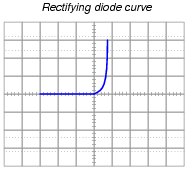
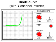
Curve tracer circuits find their real value in testing semiconductor components, whose voltage/current behaviors are nonlinear. Take for instance this characteristic curve for an ordinary rectifying diode:
|
|
The trace is flat everywhere left of center where the applied voltage is negative, indicating no diode current when it is reverse-biased. To the right of center, though, the trace bends sharply upward, indicating exponential diode current with increasing applied voltage (forward-biased) just as the "diode equation" predicts.
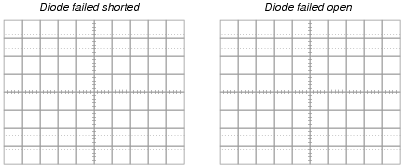
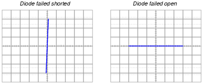
On the following grids, plot the characteristic curve for a diode that is failed shorted, and also for one that is failed open:
|
|
|
|
Notes:
Characteristic curves are not the easiest concept for some students to grasp, but they are incredibly informative. Not only can they illustrate the electrical behavior of a nonlinear device, but they can also be used to diagnose otherwise hard-to-measure faults. Letting students figure out what shorted and open curves look like is a good way to open their minds to this diagnostic tool, and to the nature of characteristic curves in general.
Although it is far from obvious, one of the oscilloscope channels will have to be ïnverted" in order for the characteristic curve to appear in the correct quadrant(s) of the display. Most dual-trace oscilloscopes have a "channel invert" function that works well for this purpose. If engaging the channel invert function on the oscilloscope flips the wrong axis, you may reverse the connections of the test device to the curve tracer circuit, flipping both axes simultaneously. Between reversing device connections and reversing one channel of the oscilloscope, you can get the curve to plot any way you want it to!
Question 4:
How is it possible to determine the polarity of a rectifying diode (which terminal is the anode, and which terminal is the cathode) from its physical appearance?
Notes:
The answer to this question, if not found in a book, may be easily determined by direct experimentation. I recommend students verify information about electronics through experimentation whenever possible, and not rely solely on someone else's documentation.
Question 5:
The "1N400x" series of rectifying diodes are very popular for low-current applications. By "1N400x," I mean the 1N4001, 1N4002, 1N4003, . . . 1N4007. Only one parameter differs between these different diode models. What parameter is this, and what is its significance?
Notes:
Be sure to ask your students where they found the information on these different diode models!
Discuss with your students the importance of this rating, and why a person might choose the 1N4007 diode for an application rather than the 1N4001, for instance.
Question 6:
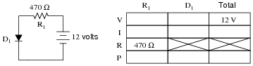
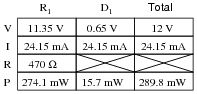
Complete the following table of values for this diode circuit, assuming a typical forward voltage drop of 0.65 volts for the diode:
|
|
|
|
Notes:
Have your students explain all their steps and calculations for solving this problem, so that you and their classmates can examine their problem-solving processes in an open and constructive forum.
Question 7:
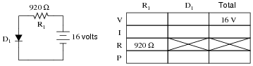
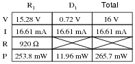
Complete the following table of values for this diode circuit, assuming a typical forward voltage drop of 0.72 volts for the diode:
|
|
|
|
Notes:
Have your students explain all their steps and calculations for solving this problem, so that you and their classmates can examine their problem-solving processes in an open and constructive forum.
Question 8:
Predict how all component voltages and currents in this circuit will be affected as a result of the following faults. Consider each fault independently (i.e. one at a time, no multiple faults):
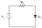
|
|
- �
- Diode D1 fails open:
- �
- Diode D1 fails shorted:
- �
- Resistor R1 fails open:
- �
- Solder bridge (short) past resistor R1:
For each of these conditions, explain why the resulting effects will occur.
- �
- Diode D1 fails open: No current in circuit, no voltage across R1, full source voltage across D1.
- �
- Diode D1 fails shorted: Increased current in circuit, full source voltage across R1, little voltage across D1.
- �
- Resistor R1 fails open: No current in circuit, no voltage across D1, full source voltage across R1.
- �
- Solder bridge (short) past resistor R1: Large current in circuit, no voltage across R1, full source voltage across D1, D1 will most likely overheat and fail.
Notes:
The purpose of this question is to approach the domain of circuit troubleshooting from a perspective of knowing what the fault is, rather than only knowing what the symptoms are. Although this is not necessarily a realistic perspective, it helps students build the foundational knowledge necessary to diagnose a faulted circuit from empirical data. Questions such as this should be followed (eventually) by other questions asking students to identify likely faults based on measurements.
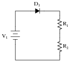
Question 9:
Predict how all component voltages and currents in this circuit will be affected as a result of the following faults. Consider each fault independently (i.e. one at a time, no multiple faults):
|
|
- �
- Diode D1 fails open:
- �
- Diode D1 fails shorted:
- �
- Resistor R1 fails open:
- �
- Resistor R2 fails open:
For each of these conditions, explain why the resulting effects will occur.
- �
- Diode D1 fails open: No current in circuit, no voltage across R1, no voltage across R2, full source voltage across D1.
- �
- Diode D1 fails shorted: Increased current in circuit, increased voltage across R1, increased voltage across R2, little voltage across D1.
- �
- Resistor R1 fails open: No current in circuit, no voltage across D1, full source voltage across R1, no voltage across R2.
- �
- Resistor R2 fails open: No current in circuit, no voltage across D1, no voltage across R1, full source voltage across R2.
Notes:
The purpose of this question is to approach the domain of circuit troubleshooting from a perspective of knowing what the fault is, rather than only knowing what the symptoms are. Although this is not necessarily a realistic perspective, it helps students build the foundational knowledge necessary to diagnose a faulted circuit from empirical data. Questions such as this should be followed (eventually) by other questions asking students to identify likely faults based on measurements.
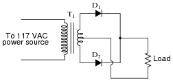
Question 10:
Predict how all component voltages and currents in this circuit will be affected as a result of the following faults. Consider each fault independently (i.e. one at a time, no multiple faults):
|
|
- �
- Diode D1 fails open:
- �
- Diode D2 fails open:
- �
- Load resistor fails open:
- �
- Transformer T1 primary winding fails open:
For each of these conditions, explain why the resulting effects will occur.
- �
- Diode D1 fails open: Load resistor receives half-wave rectified power instead of full-wave, more voltage across D1.
- �
- Diode D2 fails open: Load resistor receives half-wave rectified power instead of full-wave, more voltage across D2.
- �
- Load resistor fails open: No current on secondary side of circuit, little current in primary side of circuit, no voltage drop across either D1 or D2.
- �
- Transformer T1 primary winding fails open: No current or voltage anywhere on secondary side of circuit, no current in primary side of circuit.
Notes:
The purpose of this question is to approach the domain of circuit troubleshooting from a perspective of knowing what the fault is, rather than only knowing what the symptoms are. Although this is not necessarily a realistic perspective, it helps students build the foundational knowledge necessary to diagnose a faulted circuit from empirical data. Questions such as this should be followed (eventually) by other questions asking students to identify likely faults based on measurements.
Question 11:
An important parameter for many semiconductor components is thermal resistance, usually specified in units of degrees Celsius per Watt. What does this rating mean, and how is it related to temperature?
Notes:
Discuss the nature of heat with your students: that a differential temperature (DT) is required for transfer of heat through a medium such as a solid. Compare this phenomenon with differences of electrical potential (E) and electric current (I). How do we express an electrical conductor's ability to carry a moving charge under the influence of a potential difference?
Ask your students what difference it makes whether a semiconductor component has a high or a low thermal resistance. What is ideal for a semiconductor device, a high thermal resistance or a low thermal resistance? Why?
Question 12:
Rectifying diodes, like many other types of semiconductor components, should be derated at elevated ambient temperatures. Datasheets often provide "derating curves" that prescribe the maximum current for a range of ambient temperatures.
Explain just what "derating" is, and why it is so important for semiconductor devices.
Notes:
Discuss with your students why temperature is such a critical factor in semiconductor component operation. What happens to a semiconductor junction when it is heated? What may happen if it is heated too much?
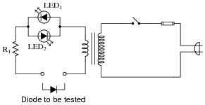
Question 13:
Describe the operation of this diode testing circuit:
|
|
Identify what the two light-emitting diodes (LEDs) will do when testing these three types of diodes:
- �
- Good diode
- �
- Diode failed shorted
- �
- Diode failed open
- �
- Good diode: one LED lit
- �
- Diode failed shorted: both LEDs lit
- �
- Diode failed open: neither LED lit
Challenge question: this circuit not only detects the presence of a good diode, but it also has the ability to identify that diode's polarity (which terminal is the cathode, and which terminal is the anode). Explain how the circuit is able to do this.
Notes:
This simple yet ingenious circuit (not my design, lest you think I'm conceited) serves the purpose of illustrating diode rectification behavior, and provides a potential project for students to build and test.
Question 14:
A useful piece of test equipment for semiconductor components is a curve tracer, used to produce current/voltage graphs for a component being tested. The graphs are typically displayed on an oscilloscope screen. Here is a very simple curve tracer circuit, designed to be used with an oscilloscope in X-Y mode:
|
|
Describe what type of trace would be drawn by this circuit on an oscilloscope screen if a resistor was being tested. Then, show the trace for a normal rectifying diode.
|
|
|
|
Challenge question: does it matter whether or not the AC source voltage for this circuit is perfectly sinusoidal?
Notes:
There is a lot to discuss in this question. Not only does the concept of "curve tracing" merit attention, but the specific operation of this circuit is worthy of investigation as well. The reason I asked students to determine the "curve" for a resistor was to introduce them to the idea of graphing component current/voltage functions, and also to allow them to analyze the circuit with a more linear component under test than a semiconductor.
An important question to ask here is why channel Y of the oscilloscope must be inverted to obtain the graphs shown. What would the graphs look like if the channel were not inverted?
The challenge question may be rephrased as, ïs the excitation voltage waveshape critical to obtaining a precise curve?" One way to demonstrate this is to use a function generator as the excitation voltage source (a transformer may be necessary to isolate the function generator ground from the oscilloscope ground!), and to try different waveshapes, watching the responses on the oscilloscope screen.
Question 15:
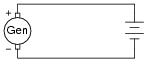
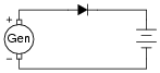
Suppose we have an application where a DC generator provides power to charge a secondary-cell battery:
|
|
The only problem with this setup is, the generator tries to act as a motor when the engine turning it is shut off, drawing power from the battery and discharging it. How could we use a rectifying diode to prevent this from happening?
|
|
Notes:
This question provides a good opportunity to review the direction of current through a battery when charging, versus when discharging. It also shows a way we can prevent the generator from "motoring" without having to use a reverse-current relay.
Question 16:
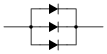
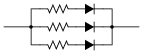
What could you do if you had an application for a rectifying diode that required a forward current rating of 2.5 amps, but you only had model 1N4001 diodes available to use? How could you use multiple 1N4001 rectifying diodes to handle this much current?
|
|
Follow-up question: while this solution should work (in theory), in practice one or more of the diodes will fail prematurely due to overheating. The fix for this problem is to connect ßwamping" resistors in series with the diodes like this:
|
|
Explain why these resistors are necessary to ensure long diode life in this application.
Notes:
The answer to this question should not be much of a challenge to your students, although the follow-up question is a bit challenging. Ask your students what purpose the swamping resistors serve. What do we know about current through the diodes if one or more of them will fail due to overheating without the swamping resistors?
What value of resistor would your students recommend for this application? What factors influence their decision regarding the resistance value?
Question 17:
Suppose you were building a simple half-wave rectifier circuit for a 480 volt AC source. The diode needs to withstand the full (peak) voltage of this AC source every other half-cycle of the waveform, or else it will fail. The bad news is, the only diodes you have available for building this rectifier circuit are model 1N4002 diodes.
Describe how you could use multiple 1N4002 rectifying diodes to handle this much reverse voltage.

|
|
Follow-up question: while this solution should work (in theory), in practice one or more of the diodes will fail prematurely due to overvoltage. The fix for this problem is to connect "divider" resistors in parallel with the diodes like this:

|
|
Explain why these resistors are necessary to ensure long diode life in this application.
Notes:
The answer to this question should not be much of a challenge to your students, although the follow-up question is a bit challenging. Ask your students what purpose the divider resistors serve. What do we know about voltage dropped across the diodes if one or more of them will fail without the divider resistors in place?
What value of resistor would your students recommend for this application? What factors influence their decision regarding the resistance value?
Question 18:
What diode performance parameter establishes the limit for maximum frequency of AC which it may rectify? If you were to examine a diode datasheet, what parameter (or parameters) would be the most important in answering this question?
Notes:
Ask your students to describe what the ïdeal" trr and Cj values would be for a diode with unlimited rectification bandwidth.
Question 19:
Find one or two real diodes and bring them with you to class for discussion. Identify as much information as you can about your diodes prior to discussion:
- �
- Polarity (which terminal is cathode and which is anode)
- �
- Forward voltage drop
- �
- Continuous current rating
- �
- Surge current rating
- �
- Continuous power rating
Be prepared to prove the forward voltage drop of your diodes in class, by using a multimeter!
Notes:
The purpose of this question is to get students to kinesthetically interact with the subject matter. It may seem silly to have students engage in a ßhow and tell" exercise, but I have found that activities such as this greatly help some students. For those learners who are kinesthetic in nature, it is a great help to actually touch real components while they're learning about their function. Of course, this question also provides an excellent opportunity for them to practice interpreting component markings, use a multimeter, access datasheets, etc.