Digital display circuits
Question 1:
What is the purpose of a seven-segment decoder circuit? What is a ßeven-segment" display, and why do we need a decoder circuit to drive it? Research the part number for a typical seven-segment decoder circuit (either CMOS or TTL).
|
|
A special decoder circuit is needed to translate 4-bit BCD codes into the particular combinations of segment activations that represent decimal digits.
Follow-up question: what does the internal schematic of a typical seven-segment display look like? Is there just one type, or are there different types of seven-segment displays?
Notes:
Be sure to ask your students to reveal the decoder datasheets they found. Once again, manufacturer datasheets contain a wealth of information, and your students will learn much by researching them.
Question 2:
| Don't just sit there! Build something!! |
Learning to analyze digital circuits requires much study and practice. Typically, students practice by working through lots of sample problems and checking their answers against those provided by the textbook or the instructor. While this is good, there is a much better way.
You will learn much more by actually building and analyzing real circuits, letting your test equipment provide the änswers" instead of a book or another person. For successful circuit-building exercises, follow these steps:
- 1.
- Draw the schematic diagram for the digital circuit to be analyzed.
- 2.
- Carefully build this circuit on a breadboard or other convenient medium.
- 3.
- Check the accuracy of the circuit's construction, following each wire to each connection point, and verifying these elements one-by-one on the diagram.
- 4.
- Analyze the circuit, determining all output logic states for given input conditions.
- 5.
- Carefully measure those logic states, to verify the accuracy of your analysis.
- 6.
- If there are any errors, carefully check your circuit's construction against the diagram, then carefully re-analyze the circuit and re-measure.
Always be sure that the power supply voltage levels are within specification for the logic circuits you plan to use. If TTL, the power supply must be a 5-volt regulated supply, adjusted to a value as close to 5.0 volts DC as possible.
One way you can save time and reduce the possibility of error is to begin with a very simple circuit and incrementally add components to increase its complexity after each analysis, rather than building a whole new circuit for each practice problem. Another time-saving technique is to re-use the same components in a variety of different circuit configurations. This way, you won't have to measure any component's value more than once.
Notes:
It has been my experience that students require much practice with circuit analysis to become proficient. To this end, instructors usually provide their students with lots of practice problems to work through, and provide answers for students to check their work against. While this approach makes students proficient in circuit theory, it fails to fully educate them.
Students don't just need mathematical practice. They also need real, hands-on practice building circuits and using test equipment. So, I suggest the following alternative approach: students should build their own "practice problems" with real components, and try to predict the various logic states. This way, the digital theory "comes alive," and students gain practical proficiency they wouldn't gain merely by solving Boolean equations or simplifying Karnaugh maps.
Another reason for following this method of practice is to teach students scientific method: the process of testing a hypothesis (in this case, logic state predictions) by performing a real experiment. Students will also develop real troubleshooting skills as they occasionally make circuit construction errors.
Spend a few moments of time with your class to review some of the "rules" for building circuits before they begin. Discuss these issues with your students in the same Socratic manner you would normally discuss the worksheet questions, rather than simply telling them what they should and should not do. I never cease to be amazed at how poorly students grasp instructions when presented in a typical lecture (instructor monologue) format!
I highly recommend CMOS logic circuitry for at-home experiments, where students may not have access to a 5-volt regulated power supply. Modern CMOS circuitry is far more rugged with regard to static discharge than the first CMOS circuits, so fears of students harming these devices by not having a "proper" laboratory set up at home are largely unfounded.
A note to those instructors who may complain about the "wasted" time required to have students build real circuits instead of just mathematically analyzing theoretical circuits:
What is the purpose of students taking your course?
If your students will be working with real circuits, then they should learn on real circuits whenever possible. If your goal is to educate theoretical physicists, then stick with abstract analysis, by all means! But most of us plan for our students to do something in the real world with the education we give them. The "wasted" time spent building real circuits will pay huge dividends when it comes time for them to apply their knowledge to practical problems.
Furthermore, having students build their own practice problems teaches them how to perform primary research, thus empowering them to continue their electrical/electronics education autonomously.
In most sciences, realistic experiments are much more difficult and expensive to set up than electrical circuits. Nuclear physics, biology, geology, and chemistry professors would just love to be able to have their students apply advanced mathematics to real experiments posing no safety hazard and costing less than a textbook. They can't, but you can. Exploit the convenience inherent to your science, and get those students of yours practicing their math on lots of real circuits!
Question 3:
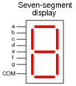
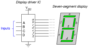
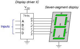
A seven segment decoder is a digital circuit designed to drive a very common type of digital display device: a set of LED (or LCD) segments that render numerals 0 through 9 at the command of a four-bit code:

|
|
The behavior of the display driver IC may be represented by a truth table with seven outputs: one for each segment of the seven-segment display (a through g). In the following table, a "1" output represents an active display segment, while a "0" output represents an inactive segment:
-
D C B A a b c d e f g Display
0 0 0 0 1 1 1 1 1 1 0 "0"
0 0 0 1 0 1 1 0 0 0 0 "1"
0 0 1 0 1 1 0 1 1 0 1 "2"
0 0 1 1 1 1 1 1 0 0 1 "3"
0 1 0 0 0 1 1 0 0 1 1 "4"
0 1 0 1 1 0 1 1 0 1 1 "5"
0 1 1 0 1 0 1 1 1 1 1 "6"
0 1 1 1 1 1 1 0 0 0 0 "7"
1 0 0 0 1 1 1 1 1 1 1 "8"
1 0 0 1 1 1 1 1 0 1 1 "9"
A real-life example such as this provides an excellent showcase for techniques such as Karnaugh mapping. Let's take output a for example, showing it without all the other outputs included in the truth table:
-
D C B A a
0 0 0 0 1
0 0 0 1 0
0 0 1 0 1
0 0 1 1 1
0 1 0 0 0
0 1 0 1 1
0 1 1 0 1
0 1 1 1 1
1 0 0 0 1
1 0 0 1 1
Plotting a Karnaugh map for output a, we get this result:

|
|
Identify adjacent groups of 1's in this Karnaugh map, and generate a minimal SOP expression from those groupings.
Note that six of the cells are blank because the truth table does not list all the possible input combinations with four variables (A, B, C, and D). With these large gaps in the Karnaugh map, it is difficult to form large groupings of 1's, and thus the resulting "minimal" SOP expression has several terms.
However, if we do not care about output a's state in the six non-specified truth table rows, we can fill in the remaining cells of the Karnaugh map with "don't care" symbols (usually the letter X) and use those cells as "wildcards" in determining groupings:

|
|
With this new Karnaugh map, identify adjacent groups of 1's, and generate a minimal SOP expression from those groupings.
|

|
|
Karnaugh map groupings with "don't care" wildcards:
|

|
|
Follow-up question: this question and answer merely focused on the a output for the BCD-to-7-segment decoder circuit. Imagine if we were to approach all seven outputs of the decoder circuit in these two fashions, first developing SOP expressions using strict groupings of "1" outputs, and then using "don't care" wildcards. Which of these two approaches do you suppose would yield the simplest gate circuitry overall? What impact would the two different solutions have on the decoder circuit's behavior for the six unspecified input combinations 1010, 1011, 1100, 1101, 1110, and 1111?
Notes:
One of the points of this question is for students to realize that bigger groups are better, in that they yield simpler SOP terms. Also, students should realize that the ability to use "don't care" states as "wildcard" placeholders in the Karnaugh map cells increases the chances of creating bigger groups.
Truth be known, I chose a pretty bad example to try to make an SOP expression from, since there are only two non-zero output conditions out of ten! Formulating a POS expression would have been easier, but that's a subject for another question!
Question 4:
A seven segment decoder is a digital circuit designed to drive a very common type of digital display device: a set of LED (or LCD) segments that render numerals 0 through 9 at the command of a four-bit code:
|
|
The behavior of the display driver IC may be represented by a truth table with seven outputs: one for each segment of the seven-segment display (a through g). In the following table, a "1" output represents an active display segment, while a "0" output represents an inactive segment:
-
D C B A a b c d e f g Display
0 0 0 0 1 1 1 1 1 1 0 "0"
0 0 0 1 0 1 1 0 0 0 0 "1"
0 0 1 0 1 1 0 1 1 0 1 "2"
0 0 1 1 1 1 1 1 0 0 1 "3"
0 1 0 0 0 1 1 0 0 1 1 "4"
0 1 0 1 1 0 1 1 0 1 1 "5"
0 1 1 0 1 0 1 1 1 1 1 "6"
0 1 1 1 1 1 1 0 0 0 0 "7"
1 0 0 0 1 1 1 1 1 1 1 "8"
1 0 0 1 1 1 1 1 0 1 1 "9"
Write the unsimplified SOP or POS expressions (choose the most appropriate form) for outputs a, b, c, and e.
|
|
|
|
Challenge question: use the laws of Boolean algebra to simplify each of the above expressions into their simplest forms.
Notes:
This shows a very practical example of SOP and POS Boolean forms, and why simplification is necessary to reduce the number of required gates to a practical minimum.
Question 5:
Examine the datasheet for a 7447 BCD-to-7-segment decoder/driver IC, and identify what input conditions need to be met in order to cause it to display any decimal digit from 0 to 9.
Follow-up question: what features differentiate the 7447 decoder/driver IC from the 7448 or 7449? How about the 74247, 74248, and 74249 decoder/driver circuits? Be prepared to show your sources when answering this question in class.
Notes:
Given that datasheets for this particular decoder/driver IC are easy to obtain and read, your students should have no trouble doing the research.
Question 6:
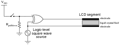
Liquid crystal display (LCD) elements require the application of AC voltage rather than DC voltage to prevent certain undesirable effects. Since logic circuits typically operate on DC power (VCC or VDD and Ground), there must be some clever way of generating the necessary AC from DC logic power in order to drive these power-thrifty display devices. Indeed, it just so happens that Exclusive-OR gates do the trick quite nicely:
|
|
Consider the square wave voltage source in this schematic as a source of alternating "high" and "low" logic states, 5 volts and 0 volts respectively. Determine what sort of voltage exists across the liquid crystal fluid with the switch in the open position as well as the closed position, and from this determine which switch position results in a darkened LCD versus a transparent LCD.
Notes:
Note that I did not specify anywhere in the question or in the answer whether the application of voltage across an LCD segment darkened or lightened that segment. This is a detail I leave up to students to research!
The particular method of generating AC from DC using an XOR gate is quite clever. Essentially, we are using the XOR's ability as a controlled inverter/buffer to reverse "polarity" of the square wave signal. Be sure to have your students explain how AC is applied across the LCD in this circuit.
Question 7:
A feature found on most 7-segment decoder/driver ICs is called ripple blanking. Describe what this feature is, and why it is used. Hint: a good source of information on this subject is a datasheet for a 7-segment decoder/driver IC.
Notes:
The answer I give here is purposefully vague, as usual. What I want students to do is research datasheets on their own and be able to show where they got their information.
Question 8:
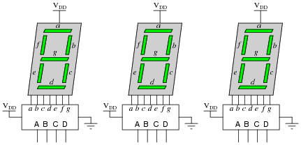
It is usually necessary to have more than one display digit for a digital system. The most obvious and direct way of driving multiple 7-segment display units is to use an equal number of BCD-to-7-segment decoders like this:
|
|
If we are driving the decoder ICs with a microprocessor or microcontroller, this direct technique unfortunately uses a lot of I/O pins. In this particular case, with three 7-segment displays, we would need to use twelve output pins on the microcontroller for the three BCD numbers:
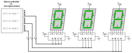
|
|
Due to limited pin count on most MPU and MCU chips, I/O lines are precious. It would be a shame to waste so many on a simple function such as driving display digits when we could use them for other tasks such as interfacing with memory devices, receiving real-world data from sensors, driving discrete control devices such as lights and solenoids, or communicating with other MPU/MCU systems. But if each digit requires four output lines for the BCD number, how can we possibly use less than twelve output lines on the processor?
One clever way to do just this exploits persistence of human vision, by driving only one digit at a time. Examine the following circuit, then explain how this "multiplexed" display system works with so few output lines. Also identify what steps the MCU/MPU must take to successfully drive all three digits so the display looks continuous:
|
|
- 1.
- Select digit number 1
- 2.
- Output BCD code for digit number 1
- 3.
- Pause for very brief (milliseconds) amount of time
- 4.
- Select digit number 2
- 5.
- Output BCD code for digit number 2
- 6.
- Pause for very brief (milliseconds) amount of time
- 7.
- Select digit number 3
- 8.
- Output BCD code for digit number 3
- 9.
- Pause for very brief (milliseconds) amount of time
- 10.
- Repeat cycle
Follow-up question: what would have to be changed in this circuit to use common-cathode LED 7-segment displays instead of common-anode displays?
Notes:
Be sure to ask your students where they were able to research multiplexed 7-segment displays, and what they think about this particular technique of producing a "continuous" three-digit decimal display by flashing them very rapidly. Clever techniques such as this are often necessary to make the most of limited hardware.
By the way, I have omitted the customary LED current-limiting resistors from the schematic diagrams, for brevity's sake. See if any of your students are able to catch this omission!
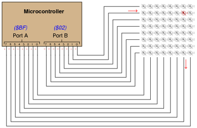
Question 9:
Digital computers communicate with external devices through ports: sets of terminals usually arranged in groups of 4, 8, 16, or more. These terminals may be set to high or low logic states by writing a program for the computer that sends a numerical value to the port. For example, here is an illustration of a microcontroller being instructed to send the hexadecimal number 2B to port A and A9 to port B:
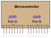
|
|
Suppose we wished to use the first seven bits of each port (pins 0 through 6) to drive two 7-segment, common-cathode displays, rather than use BCD-to-7-segment decoder ICs:
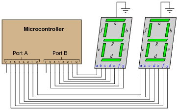
|
|
Write the necessary hexadecimal values to be output at ports A and B to generate the display "42" at the two 7-segment display units.
Note that the following answers are also valid:
Port A = DB16 Port B = E616
Follow-up question: write these same numerical values in decimal rather than hexadecimal.
Notes:
The root of this question is little more than binary-to-hexadecimal conversion, but it also introduces students to the concept of controlling bit states in microcomputer ports by writing hex values. As such, this question is very practical! Although it is unlikely that someone would omit BCD-to-7-segment decoders when building a two-digit decimal display (because doing it this way uses so many more precious microcontroller I/O pins), it is certainly possible! There are many applications other than this where you need to get the microcontroller to output a certain combination of high and low states, and the fastest way to program this is to output hex values to the ports.
In case students ask, let them know that a dollar sign prefix is sometimes used to denote a hexadecimal number. Other times, the prefix 0x is used (e.g., $F3 and 0xF3 mean the same thing).
Question 10:
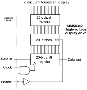
The MM58342 high-voltage display driver IC from National Semiconductor serves as an interface between either a microprocessor or microcontroller and a high-voltage vacuum fluorescent (VF) display panel. The IC reads and conditions 20 bits of data to drive 20 "grids" in such a display. When combined with a similar driver driving the anodes of the same VF display, individual pixels (or combinations of pixels) may be controlled (lit).
An interesting feature of this IC is that it receives the 20 bits of data serially (one at a time), through a single input pin:
|
|
Read the datasheet for this device, then comment on why you think a serial (rather than parallel) data input format was chosen. Also describe the sequence of operation for loading data into this IC and outputting that data to the 20 output lines.
Notes:
While this question introduces the concept of a vacuum-fluorescent (VF) display, it also serves as a review of shift register and latch technology. The block diagram should be informative enough for most students to be able to figure out at least an approximate procedure for loading and outputting data.
It is interesting to note (and discuss with your students) that this IC does not decode characters. It merely conditions and outputs bits of information to the grids of a VF display. Ask your students, then, where they think the patterns of ön" and öff" pixels must be generated to form specific characters on the display.
Question 11:
One new technology entering the market is organic light-emitting diodes, or OLEDs. Describe what these are, and why they hold so much promise for electronic display device elements.
Notes:
This question is destined for obsolescence, as organic LEDs will either become so popular as to lose their novelty ("new technology") or become supplanted by something even better. But for now (May 2005), they are worthy of their own question in the Socratic Electronics project!
Question 12:
Two electronics students attempt to build 7-segment display circuits, one using a 7447 decoder/driver IC and the other using a 7448. Both students connect their ICs to common-cathode 7-segment displays as such:
|
|
The student using the 7448 notices the LED segments glowing faintly, but the patterns are not correct for the digits that are supposed to be displayed. The student using the 7447 has an even worse problem: no light at all! Both have checked and re-checked their wiring, to no avail. It seems as though all the connections are in the right place.
What do you think the problem is? Hint: consult datasheets for both chips to find clues!
Follow-up question: trace the direction of electron flow through the wires between the decoder chip and the display.
Notes:
This question provides an excellent opportunity to discuss the difference between sourcing and sinking current, as well as the importance of knowing what the output stage of an IC looks like internally.
Question 13:
An obsolete display technology that still finds enthusiastic followers in the hobbyist world, called Nixie tubes, relies on a BCD-to-10 decoder to drive one of ten different metal cathodes inside a neon-filled glass bulb. For each BCD code, exactly one of the cathode figures inside the "Nixie tube" will glow, causing that numeral to shine with a pink-orange light. The tube receives power through a common anode (usually over 150 volts DC).
A friend of yours is trying to build his own Nixie tube display circuit, but is experiencing problems. He wants to use a 7442 BCD-to-10 decoder to drive ten discrete transistors, each one handling the current for a digit in the tube. Being cautious, your friend decides to connect just one of the Nixie tube digits to a transistor, and then to the 7442, to see if the idea works (before connecting all ten).
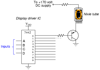
|
|
Unfortunately, that one digit begins to glow the moment the high-voltage DC supply is turned on, even before the 7442 chip receives power! And after that, the 7442 gets warm to the touch, which is not good.
Thinking he has damaged the 7442 IC, your friend turns to you for advice. Did he do anything wrong here? Explain what advice you would give to him.
Follow-up question: comment on your friends' strategy to connect only one transistor to one Nixie tube cathode for a test. Was this a good idea? Why or why not? Did doing this save the 7442 from further damage?
Notes:
I have left the answer purposefully vague so that students will have to figure out how to properly use BJTs to drive the Nixie tube cathodes. This is a good opportunity for them to review BJT theory and switch application use, so don't spoil it by giving away the answer!
Question 14:
Liquid crystal display (LCD) technology used to have very narrow viewing angles. Anyone who remembers the first LCD displays on portable personal computers will recall how you could only see the display if you viewed it perpendicular to the display surface, or at a very slight angle from perpendicular.
Modern LCD technology is much better, is still not as good as viewing printed paper, the "gold standard" for non-emissive display. One term frequently used to describe the quality of viewing with regard to angle is Lambertian. Define what "Lambertian" means with regard to display surfaces.
Notes:
This question is destined for obsolescence, as Lambertian displays will likely become a reality in the next several years. But for now (May 2005), it is a term worth defining in the introductory study of display technologies.
An example of an early attempt at full-Lambertian display is the Gyricon technology developed by Xerox. Research this and be prepared to discuss it with your students as an example of a novel approach for non-emissive electronic displays.
Question 15:
One method of driving pixels in a grid-based display is to organize the pixels into rows and columns, then select individual pixels for illumination by the intersection of a specific row line and a specific column line. In this example, we are controlling an 8 × 8 grid of LEDs with two 8-bit (1-byte) ports of a microcontroller:
|
|
Note that a high state is required on one of port B's pins to activate a row, and a low state is required on one of port A's pins to activate a column, because the LED anodes connect to port A and the LED cathodes connect to port B.
Determine the hexadecimal codes we would need to output at ports A and B to energize the LED in the far lower-left corner of the 8 × 8 grid.
Port A =
Port B =