Voltage divider circuits
Question 1:
| Don't just sit there! Build something!! |
Learning to mathematically analyze circuits requires much study and practice. Typically, students practice by working through lots of sample problems and checking their answers against those provided by the textbook or the instructor. While this is good, there is a much better way.
You will learn much more by actually building and analyzing real circuits, letting your test equipment provide the änswers" instead of a book or another person. For successful circuit-building exercises, follow these steps:
- 1.
- Carefully measure and record all component values prior to circuit construction.
- 2.
- Draw the schematic diagram for the circuit to be analyzed.
- 3.
- Carefully build this circuit on a breadboard or other convenient medium.
- 4.
- Check the accuracy of the circuit's construction, following each wire to each connection point, and verifying these elements one-by-one on the diagram.
- 5.
- Mathematically analyze the circuit, solving for all values of voltage, current, etc.
- 6.
- Carefully measure those quantities, to verify the accuracy of your analysis.
- 7.
- If there are any substantial errors (greater than a few percent), carefully check your circuit's construction against the diagram, then carefully re-calculate the values and re-measure.
Avoid very high and very low resistor values, to avoid measurement errors caused by meter "loading". I recommend resistors between 1 kW and 100 kW, unless, of course, the purpose of the circuit is to illustrate the effects of meter loading!
One way you can save time and reduce the possibility of error is to begin with a very simple circuit and incrementally add components to increase its complexity after each analysis, rather than building a whole new circuit for each practice problem. Another time-saving technique is to re-use the same components in a variety of different circuit configurations. This way, you won't have to measure any component's value more than once.
Notes:
It has been my experience that students require much practice with circuit analysis to become proficient. To this end, instructors usually provide their students with lots of practice problems to work through, and provide answers for students to check their work against. While this approach makes students proficient in circuit theory, it fails to fully educate them.
Students don't just need mathematical practice. They also need real, hands-on practice building circuits and using test equipment. So, I suggest the following alternative approach: students should build their own "practice problems" with real components, and try to mathematically predict the various voltage and current values. This way, the mathematical theory "comes alive," and students gain practical proficiency they wouldn't gain merely by solving equations.
Another reason for following this method of practice is to teach students scientific method: the process of testing a hypothesis (in this case, mathematical predictions) by performing a real experiment. Students will also develop real troubleshooting skills as they occasionally make circuit construction errors.
Spend a few moments of time with your class to review some of the "rules" for building circuits before they begin. Discuss these issues with your students in the same Socratic manner you would normally discuss the worksheet questions, rather than simply telling them what they should and should not do. I never cease to be amazed at how poorly students grasp instructions when presented in a typical lecture (instructor monologue) format!
A note to those instructors who may complain about the "wasted" time required to have students build real circuits instead of just mathematically analyzing theoretical circuits:
What is the purpose of students taking your course?
If your students will be working with real circuits, then they should learn on real circuits whenever possible. If your goal is to educate theoretical physicists, then stick with abstract analysis, by all means! But most of us plan for our students to do something in the real world with the education we give them. The "wasted" time spent building real circuits will pay huge dividends when it comes time for them to apply their knowledge to practical problems.
Furthermore, having students build their own practice problems teaches them how to perform primary research, thus empowering them to continue their electrical/electronics education autonomously.
In most sciences, realistic experiments are much more difficult and expensive to set up than electrical circuits. Nuclear physics, biology, geology, and chemistry professors would just love to be able to have their students apply advanced mathematics to real experiments posing no safety hazard and costing less than a textbook. They can't, but you can. Exploit the convenience inherent to your science, and get those students of yours practicing their math on lots of real circuits!
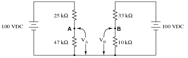
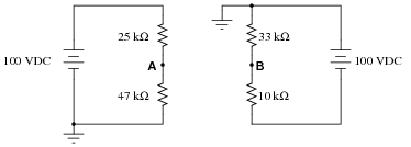
Question 2:
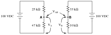
Calculate the output voltages of these two voltage divider circuits (VA and VB):
|
|
Now, calculate the voltage between points A (red lead) and B (black lead) (VAB).
VB = + 23.26 V
VAB = + 42.02 V (point A being positive relative to point B)
Challenge question: what would change if the wire connecting the two voltage divider circuits together were removed?
|
|
Notes:
In this question, I want students to see how the voltage between the two dividers' output terminals is the difference between their individual output voltages. I also want students to see the notation used to denote the voltages (use of subscripts, with an applied reference point of ground). Although voltage is always and forever a quantity between two points, it is appropriate to speak of voltage being ät" a single point in a circuit if there is an implied point of reference (ground).
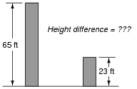
It is possible to solve for VAB without formally appealing to Kirchhoff's Voltage Law. One way I've found helpful to students is to envision the two voltages (VA and VB) as heights of objects, asking the question of "How much height difference is there between the two objects?"
|
|
The height of each object is analogous to the voltage dropped across each of the lower resistors in the voltage divider circuits. Like voltage, height is a quantity measured between two points (the top of the object and ground level). Also like the voltage VAB, the difference in height between the two objects is a measurement taken between two points, and it is also found by subtraction.
Question 3:
We know that the current in a series circuit may be calculated with this formula:
|
We also know that the voltage dropped across any single resistor in a series circuit may be calculated with this formula:
|
Combine these two formulae into one, in such a way that the I variable is eliminated, leaving only ER expressed in terms of Etotal, Rtotal, and R.
|
Follow-up question: algebraically manipulate this equation to solve for Etotal in terms of all the other variables. In other words, show how you could calculate for the amount of total voltage necessary to produce a specified voltage drop (ER) across a specified resistor (R), given the total circuit resistance (Rtotal).
Notes:
Though this "voltage divider formula" may be found in any number of electronics reference books, your students need to understand how to algebraically manipulate the given formulae to arrive at this one.
Question 4:
Determine the amount of voltage dropped by each resistor in this circuit, if each resistor has a color code of Brn, Blk, Red, Gld (assume perfectly precise resistance values - 0% error):
|
|
Also, determine the following information about this circuit:
- �
- Current through each resistor
- �
- Power dissipated by each resistor
- �
- Ratio of each resistor's voltage drop to battery voltage ([(ER)/(Ebat)])
- �
- Ratio of each resistor's resistance to the total circuit resistance ([R/(Rtotal)])
Current through each resistor = 1.5 mA
Power dissipated by each resistor = 2.25 mW
Voltage ratio = [1/3]
Resistance ratio = [1/3]
Follow-up question: are the two ratios' equality a coincidence? Explain your answer.
Notes:
When performing the mathematical analysis on this circuit, there is more than one possible sequence of steps to obtaining the solutions. Different students in your class may very well have different solution sequences, and it is a good thing to have students share their differing problem-solving techniques before the whole class.
An important aspect of this question is for students to observe the identical ratios (voltage versus resistance), and determine whether or not these ratios are equal by chance or equal by necessity. Ask your students, "What kind of evidence would prove these ratios were merely equal by chance?" Setting mathematics aside and viewing this circuit from a purely experimental point of view, ask your students what data could possibly prove these ratios to be equal by chance in this particular case? Hint: it would only take a single example to prove this!
Question 5:
Calculate the voltage dropped by each of these resistors, given a battery voltage of 9 volts. The resistor color codes are as follows (assume 0% error on all resistor values):
- R1 = Brn, Grn, Red, Gld
- R2 = Yel, Vio, Org, Gld
- R3 = Red, Grn, Red, Gld
- R4 = Wht, Blk, Red, Gld
|
|
Now, re-calculate all resistor voltage drops for a scenario where the total voltage is different:
|
|
| First scenario: | Second scenario: |
| ER1 = 0.225 volts | ER1 = 0.45 volts |
| ER2 = 7.05 volts | ER2 = 14.1 volts |
| ER3 = 0.375 volts | ER3 = 0.75 volts |
| ER4 = 1.35 volts | ER4 = 2.7 volts |
Follow-up question: what do you notice about the ratios of the voltages between the two scenarios?
Notes:
Ask your students if they notice any pattern between the voltage drops of the first scenario and the voltage drops of the second scenario. What does this pattern tell us about the nature of voltage divider circuits?
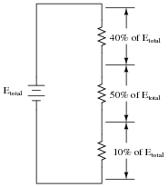
Question 6:
Design a voltage divider circuit that splits the power supply voltage into the following percentages:
|
|
|
Notes:
Different students will likely arrive at different solutions for this design task. Have your students share their differing solutions, emphasizing that there is often more than one acceptable solution to a problem!
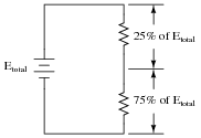
Question 7:
Design a voltage divider circuit that splits the power supply voltage into the following percentages:
|
|
Notes:
Different students will likely arrive at different solutions for this design task. Have your students share their differing solutions, emphasizing that there is often more than one acceptable solution to a problem!
Question 8:
Calculate VA (voltage at point A with respect to ground) and VB (voltage at point B with respect to ground) in the following circuit:
|
|
Now, calculate the voltage between points A and B (VAB).
VB = -76.74 V
VAB = 142.02 V (point A being positive relative to point B)
If you are experiencing difficulty in your analysis of this circuit, you might want to refer to this re-drawing:
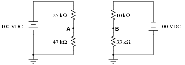
|
|
To make it even easier to visualize, remove the ground symbols and insert a wire connecting the lower wires of each circuit together:
|
|
It's all the same circuit, just different ways of drawing it!
Follow-up question: identify, for a person standing on the ground (with feet electrically common to the ground symbols in the circuits), all the points on the circuits which would be safe to touch without risk of electric shock.
Notes:
New students often experience difficulty with problems such as this, where ground connections are located in ßtrange" places. The alternate diagram may be helpful in this case.
The follow-up question challenges students to apply the practical rule-of-thumb (30 volts or more is considered potentially a source of electric shock) to a circuit that is otherwise quite abstract.
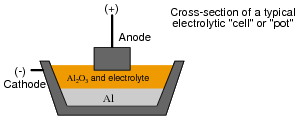
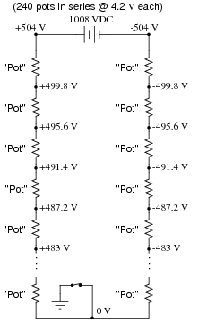
Question 9:
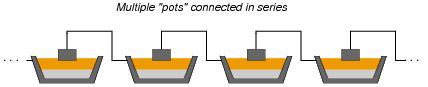
Many manufacturing processes are electrochemical in nature, meaning that electricity is used to promote or force chemical reactions to occur. One such industry is aluminum smelting, where large amounts of DC current (typically several hundred thousand amperes!) is used to turn alumina (Al2O3) into pure metallic aluminum (Al):
|
|
The alumina/electrolyte mixture is a molten bath of chemicals, lighter than pure aluminum itself. Molecules of pure aluminum precipitate out of this mix and settle at the bottom of the "pot" where the molten metal is periodically pumped out for further refining and processing. Fresh alumina powder is periodically dropped into the top of the pot to replenish what is converted into aluminum metal.
Although the amount of current necessary to smelt aluminum in this manner is huge, the voltage drop across each pot is only about 4 volts. In order to keep the voltage and current levels reasonable in a large smelting facility, many of these pots are connected in series, where they act somewhat like resistors (being energy loads rather than energy sources):
|
|
A typical "pot-line" might have 240 pots connected in series. With a voltage drop of just over 4 volts apiece, the total voltage powering this huge series circuit averages around 1000 volts DC:
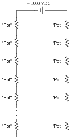
|
|
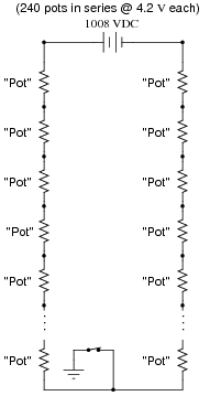
With this level of voltage in use, electrical safety is a serious consideration! To ensure the safety of personnel if they must perform work around a pot, the system is equipped with a "movable ground," consisting of a large switch on wheels that may be connected to the steel frame of the shelter (with concrete pilings penetrating deep into the soil) and to the desired pot. Assuming a voltage drop of exactly 4.2 volts across each pot, note what effect the ground's position has on the voltages around the circuit measured with respect to ground:
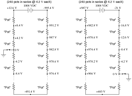
|
|
Determine the voltages (with respect to earth ground) for each of the points (dots) in the following schematic diagram, for the ground location shown:
|
|
|
|
Follow-up question: assuming each of the pots acts exactly like a large resistor (which is not entirely true, incidentally), what is the resistance of each pot if the total "potline" current is 150 kA at 4.2 volts drop per pot?
Notes:
I (Tony Kuphaldt) worked for over six years at an aluminum smelter in northwest Washington state (United States of America), where part of my job as an electronics technician was to maintain the measurement and control instrumentation for three such "potlines." Very interesting work. The magnetic field emanating from the busbars conducting the 150 kA of current was strong enough to hold a screwdriver vertical, if you let it stand on the palm of your hand, assuming your hand was just a few feet away from the horizontal bus and even with its centerline!
Discuss with your students how voltage measured with respect to ground is an important factor in determining personnel safety. Being that your feet constitute an electrical contact point with the earth (albeit a fairly high-resistance contact), it becomes possible to be shocked by touching only one point in a grounded circuit.
In your discussion, it is quite possible that someone will ask, "Why not eliminate the ground entirely, and leave the whole potline floating? Then there would be no shock hazard from a single-point contact, would there?" The answer to this (very good) question is that accidental groundings are impossible to prevent, and so by not having a firm (galvanic) ground connection in the circuit, no point in that circuit will have a predictable voltage with respect to earth ground. This lack of predictability is a worse situation than having known dangerous voltages at certain points in a grounded system.
Question 10:
Draw an equivalent schematic diagram for this circuit, then calculate the voltage dropped by each of these resistors, given a battery voltage of 9 volts. The resistor color codes are as follows (assume 0% error on all resistor values):
- R1 = Brn, Grn, Red, Gld
- R2 = Yel, Vio, Org, Gld
- R3 = Red, Grn, Red, Gld
- R4 = Wht, Blk, Red, Gld
- R5 = Brn, Blk, Org, Gld

|
|
Compare the voltage dropped across R1, R2, R3, and R4, with and without R5 in the circuit. What general conclusions may be drawn from these voltage figures?
|
|
| With R5 in the circuit: | Without R5 in the circuit: |
| ER1 = 0.226 volts | ER1 = 0.225 volts |
| ER2 = 7.109 volts | ER2 = 7.05 volts |
| ER3 = 0.303 volts | ER3 = 0.375 volts |
| ER4 = 1.36 volts | ER4 = 1.35 volts |
Notes:
Ask your students to describe the "with R5 / without R5" voltage values in terms of either increase or decrease. A general pattern should be immediately evident when this is done.
Question 11:
The formula for calculating voltage across a resistor in a series circuit is as follows:
|
In a simple-series circuit with one voltage source and three resistors, we may re-write this formula to be more specific:
|
Suppose we have such a series circuit with a source voltage of 15 volts, and resistor values of R1 = 1 kW and R2 = 8.1 kW. Algebraically manipulate this formula to solve for R3 in terms of all the other variables, then determine the necessary resistance value of R3 to obtain a 0.2 volt drop across resistor R1.
|
R3 = 65.9 kW
Notes:
This question provides students with another practical application of algebraic manipulation. Ask individual students to show their steps in manipulating the voltage divider formula to solve for R3, so that all may see and learn.
Question 12:
What will happen to the voltages across resistors R1 and R2 when the load is connected to the divider circuit?
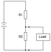
|
|
Notes:
This is a very important concept to be learned about voltage divider circuits: how they respond to applications of load. Not a single calculation need be done to arrive at the answer for this question, so encourage your students to think qualitatively rather than quantitatively. Too many students have the habit of reaching for their calculators when faced with a problem like this, when they really just need to apply more thought.
Question 13:
Calculate both the maximum and the minimum amount of voltage obtainable from this potentiometer circuit (as measured between the wiper and ground):
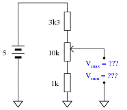
|
|
Vmin = 0.35 volts
Notes:
Be sure to ask your students how they obtained their answers, not just what the answers are. There is more than one correct way to analyze this circuit!
Incidentally, there is nothing significant about the use of European schematic symbols in this question. I did this simply to provide students with more exposure to this schematic convention.
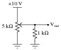
Question 14:
Calculate both the maximum and the minimum amount of voltage that each of the voltmeters will register, at each of the potentiometer's extreme positions:
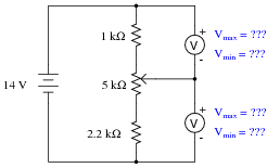
|
|
Vmax = 10.24 volts Vmin = 1.71 volts
For lower voltmeter:
Vmax = 12.29 volts Vmin = 3.76 volts
Follow-up question: identify the positions in which the potentiometer wiper must be set in order to obtain all four of the voltage readings shown above.
Notes:
Be sure to ask your students how they obtained their answers, not just what the answers are. There is more than one correct way to analyze this circuit!
Question 15:
As adjustable devices, potentiometers may be set at a number of different positions. It is often helpful to express the position of a potentiometer's wiper as a fraction of full travel: a number between 0 and 1, inclusive. Here are several pictorial examples of this, with the variable m designating this travel value (the choice of which alphabetical character to use for this variable is arbitrary):
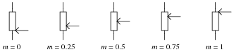
|
|
Using an algebraic variable to represent potentiometer position allows us to write equations describing the outputs of voltage divider circuits employing potentiometers. Note the following examples:
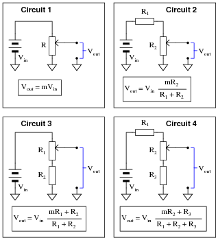
|
|
Algebraically manipulate these four equations so as to solve for m in each case. This will yield equations telling you where to set each potentiometer to obtain a desired output voltage given the input voltage and all resistance values (m = �).
|
|
|
|
Hint: in order to avoid confusion with all the subscripted R variables (R1, R2, and R3) in your work, you may wish to substitute simpler variables such as a for R1, b for R2, etc. Similarly, you may wish to substitute x for Vin and y for Vout. Using shorter variable names makes the equations easier to manipulate. See how this simplifies the equation for circuit 2:
|
|
Notes:
The main purpose of this question is to provide algebraic manipulation practice for students, as well as shown them a practical application for algebraic substitution. The circuits are almost incidental to the math.
Question 16:
When the 5 kW potentiometer in this circuit is set to its 0%, 25%, 50%, 75%, and 100% positions, the following output voltages are obtained (measured with respect to ground, of course):
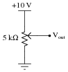
|
|
- �
- At 0% setting, Vout = 0 V
- �
- At 25% setting, Vout = 2.5 V
- �
- At 50% setting, Vout = 5 V
- �
- At 75% setting, Vout = 7.5 V
- �
- At 100% setting, Vout = 10 V
Calculate what the output voltages will be if a 1 kW load resistor is connected between the "Vout" terminal and ground:
|
|
- �
- At 0% setting, Vout =
- �
- At 25% setting, Vout =
- �
- At 50% setting, Vout =
- �
- At 75% setting, Vout =
- �
- At 100% setting, Vout =
- �
- At 0% setting, Vout = 0 V
- �
- At 25% setting, Vout = 1.29 V
- �
- At 50% setting, Vout = 2.22 V
- �
- At 75% setting, Vout = 3.87 V
- �
- At 100% setting, Vout = 10 V
Notes:
This question is really nothing more than five loaded voltage divider problems packed into one! It is a very practical question, as potentiometers are very often used as variable voltage dividers, and students must realize the effects a load resistance will have on the characteristics of such dividers. Point out to them the extreme nonlinearity created by the inclusion of the load resistance.
Question 17:
Determine the voltages (with respect to ground) at points A and B in this circuit under four different conditions: both loads off, load 1 on (only), load 2 on (only), and both loads on:
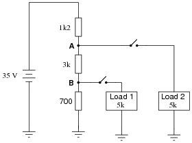
|
|
-
Voltage Both loads off Load 1 on (only) Load 2 on (only) Both loads on
VA
VB
-
Voltage Both loads off Load 1 on (only) Load 2 on (only) Both loads on
VA 26.4 volts 26.3 volts 22.4 volts 22.3 volts
VB 5 volts 4.46 volts 4.23 volts 3.78 volts
Notes:
Students will have to re-consider (and possible re-draw) the circuit for each loading condition, which is one of the major points of this question. The fact that a circuit can "change" just by throwing a switch is an important concept for electronics students to grasp.
Another concept employed in this question is that of voltages specified at single points with an implied reference of ground. Note to students how each voltage was simply referenced by a single letter, either A or B. Of course there is no such thing as voltage at a single point in any circuit, so we need another point to reference, and that point is ground. This is very commonly seen in electronic circuits of all types, and is a good thing to be exposed to early on in one's electronics education.
A much less obvious point of this question is to subtly introduce the concept of discrete states (loading conditions) available with a given number of boolean elements (switches). Given two load switches, there are four possible states of circuit loading, previewing binary states in digital circuits.
Question 18:
Calculate both the total resistance of this voltage divider circuit (as ßeen" from the perspective of the 25 volt source) and its output voltage (as measured from the Vout terminal to ground):
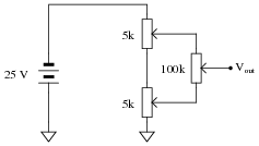
|
|
Note that all potentiometers in this circuit are set exactly to mid-position (50%, or m = 0.5).
Vout = -12.5 V
Notes:
Ask your students to explain why the output voltage is expressed as a negative quantity. Is this important, or is it an inconsequential detail that may be omitted if desired?
Also, it might be good to ask your students to show the equivalent circuit (made up entirely of fixed resistors) that they drew in route to solving for total resistance and output voltage. Encourage them to take this step if they have not already, for although it does involve ëxtra" work, it helps greatly in keeping track of the series-parallel relationships and all calculated circuit values.
Question 19:
Calculate both the total resistance of this voltage divider circuit (as ßeen" from the perspective of the 25 volt source) and its output voltage (as measured from the Vout terminal to ground):
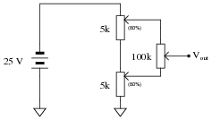
|
|
Note that the two 5 kW potentiometers are set to their 80% positions (m = 0.8), while the 100 kW potentiometer is set exactly to mid-position (50%, or m = 0.5).
Vout = -16.341 V
Notes:
Ask your students to explain why the output voltage is expressed as a negative quantity. Is this important, or is it an inconsequential detail that may be omitted if desired?
Also, it might be good to ask your students to show the equivalent circuit (made up entirely of fixed resistors) that they drew in route to solving for total resistance and output voltage. Encourage them to take this step if they have not already, for although it does involve ëxtra" work, it helps greatly in keeping track of the series-parallel relationships and all calculated circuit values.
Question 20:
Calculate both the total resistance of this voltage divider circuit (as ßeen" from the perspective of the 25 volt source) and its output voltage (as measured from the Vout terminal to ground):
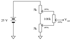
|
|
Note that the upper 5 kW potentiometer is set to its 20% position (m = 0.2), while the lower 5 kW potentiometer is set to its 90% position (m = 0.9), and the 100 kW potentiometer is set to its 40% position (m = 0.4).
Vout = 12.756 V
Notes:
Ask your students to explain why the output voltage is expressed as a positive quantity. Is this significant, or could it be properly expressed as a negative quantity as well? In other words, is this an absolute value of a voltage which may be negative, or is it definitely a positive voltage? How may we tell?
Also, it might be good to ask your students to show the equivalent circuit (made up entirely of fixed resistors) that they drew in route to solving for total resistance and output voltage. Encourage them to take this step if they have not already, for although it does involve ëxtra" work, it helps greatly in keeping track of the series-parallel relationships and all calculated circuit values.
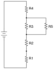
Question 21:
Which voltage divider circuit will be least affected by the connection of identical loads? Explain your answer.
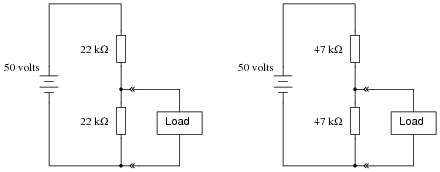
|
|
What advantage does the other voltage divider have over the circuit that is least affected by the connection of a load?
Notes:
Some students may be confused by the lack of a resistance value given for the load. Without a given value, how can they proceed with any calculations? Ask the other students how they solved this problem: how did they overcome the problem of not having a load resistance value to work with?
Question 22:
A student builds the following voltage divider circuit so she can power a 6-volt lamp from a 15-volt power supply:
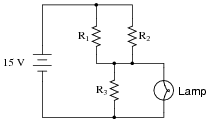
|
|
When built, the circuit works just as it should. However, after operating successfully for hours, the lamp suddenly goes dark. Identify all the possible faults you can think of in this circuit which could account for the lamp not glowing anymore.
- �
- Lamp burned out
- �
- 15-volt power supply failed
- �
- Resistors R1 and R2 simultaneously failed open
Follow-up question: although the third possibility mentioned here is certainly valid, it is less likely than any single failure. Explain why, and how this general principle of considering single faults first is a good rule to follow when troubleshooting systems.
Notes:
Have fun with your students figuring out all the possible faults which could account for the lamp going dark! Be sure to include wires and wire connections in your list.
The follow-up question is intended to get students to come up with their own version of Occam's Razor: the principle that the simplest explanation for an observed phenomenon is probably the correct one.
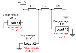
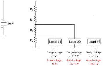
Question 23:
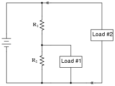
One of the resistors in this voltage divider circuit is failed open. Based on the voltage readings shown at each load, determine which one it is:
|
|
Notes:
Discuss with your students how they were able to predict R1 was the faulty resistor. Is there any particular clue in the diagram indicating R1 as the obvious problem?
Question 24:
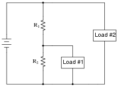
One of the resistors in this voltage divider circuit is failed open. Based on the voltage readings shown at each load, determine which one it is:

|
|
Notes:
Discuss with your students how they were able to predict R2 was the faulty resistor. Is there any particular clue in the diagram indicating R2 as the obvious problem?
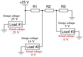
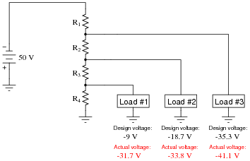
Question 25:
One of the resistors in this voltage divider circuit is failed (either open or shorted). Based on the voltage readings shown at each load, determine which one and what type of failure it is:
|
|
Follow-up question: note that the voltage at load #2 is not fully 25 volts. What does this indicate about the nature of R1's failure? Be as specific as you can in your answer.
Notes:
Discuss with your students how they were able to predict R1 was the faulty resistor. Is there any particular clue in the diagram indicating R1 as the obvious problem? Some students may suspect an open failure in resistor R3 could cause the same effects, but there is a definite way to tell that the problem can only come from a short in R1 (hint: analyze resistor R2).
Explain that not all ßhorted" failures are "hard" in the sense of being direct metal-to-metal wire connections. Quite often, components will fail shorted in a ßofter" sense, meaning they still have some non-trivial amount of electrical resistance.
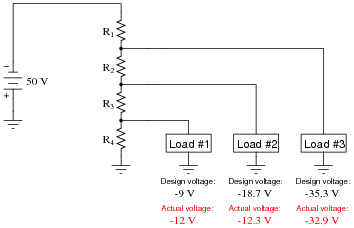
Question 26:
One of the resistors in this voltage divider circuit has failed (either open or shorted). Based on the voltage readings shown at each load, comparing what each load voltage is versus what it should be, determine which resistor has failed and what type of failure it is:
|
|
Notes:
Use this question as an opportunity to discuss troubleshooting strategies with your students. A helpful hint in dealing with this kind of problem is to categorize each load voltage as either being greater or less than normal. Forget the negative signs here: we're dealing strictly with absolute values (in other words, -25 volts is a "greater" voltage than -20 volts). Once each load voltage has been categorized thusly, it is possible to isolate the location and nature of the fault without having to deal with numbers at all!
Question 27:
One of the resistors in this voltage divider circuit has failed (either open or shorted). Based on the voltage readings shown at each load, comparing what each load voltage is versus what it should be, determine which resistor has failed and what type of failure it is:
|
|
Notes:
Use this question as an opportunity to discuss troubleshooting strategies with your students. A helpful hint in dealing with this kind of problem is to categorize each load voltage as either being greater or less than normal. Forget the negative signs here: we're dealing strictly with absolute values (in other words, -25 volts is a "greater" voltage than -20 volts). Once each load voltage has been categorized thusly, it is possible to isolate the location and nature of the fault without having to deal with numbers at all!
Question 28:
One of the resistors in this voltage divider circuit has failed (either open or shorted). Based on the voltage readings shown at each load, comparing what each load voltage is versus what it should be, determine which resistor has failed and what type of failure it is:
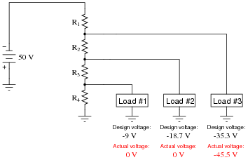
|
|
Notes:
Use this question as an opportunity to discuss troubleshooting strategies with your students. A helpful hint in dealing with this kind of problem is to categorize each load voltage as either being greater or less than normal. Forget the negative signs here: we're dealing strictly with absolute values (in other words, -25 volts is a "greater" voltage than -20 volts). Once each load voltage has been categorized thusly, it is possible to isolate the location and nature of the fault without having to deal with numbers at all!
Question 29:
One of the resistors in this voltage divider circuit has failed (either open or shorted). Based on the voltage readings shown at each load, comparing what each load voltage is versus what it should be, determine which resistor has failed and what type of failure it is:
|
|
Notes:
Use this question as an opportunity to discuss troubleshooting strategies with your students. A helpful hint in dealing with this kind of problem is to categorize each load voltage as either being greater or less than normal. Forget the negative signs here: we're dealing strictly with absolute values (in other words, -25 volts is a "greater" voltage than -20 volts). Once each load voltage has been categorized thusly, it is possible to isolate the location and nature of the fault without having to deal with numbers at all!
Question 30:
Size the resistor in this voltage divider circuit to provide 3.2 volts to the load, assuming that the load will draw 10 mA of current at this voltage:
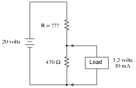
|
|
As part of your design, include the power dissipation ratings of both resistors.
Notes:
Ask your students what would change in this divider circuit if the load were to suddenly draw more, or less, current.
Question 31:
Size the resistor in this voltage divider circuit to provide 5 volts to the load, assuming that the load will draw 75 mA of current at this voltage:
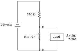
|
|
As part of your design, include the power dissipation ratings of both resistors.
Notes:
Ask your students what would change in this divider circuit if the load were to suddenly draw more, or less, current.
Question 32:
Size both resistors in this voltage divider circuit to provide 6 volts to the load, assuming that the load will draw 7 mA of current at this voltage, and to have a "bleeder" current of 1 mA going through R2:
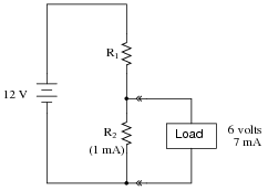
|
|
As part of your design, include the power dissipation ratings of both resistors.
Notes:
This may seem like a tricky problem to some students, as though it is lacking in information. All the necessary information is there, however. Students just need to think through all the laws of series-parallel circuits to piece together the necessary resistor values from the given specifications.
Question 33:
Explain what will happen to the first load's voltage and current in this voltage divider circuit, as a second load is connected as shown:
|
|
Notes:
It is important for students to realize that the second load constitutes a separate parallel branch in the circuit, which (ideally) has no effect on the rest of the circuit.
Question 34:
Explain what will happen to the first load's voltage and current in this voltage divider circuit if the second load develops a short-circuit fault:
|
|
Notes:
While it is important for students to realize that the second load constitutes a separate parallel branch in the circuit and therefore (ideally) has no effect on the rest of the circuit, it is crucial for them to understand that such an ideal condition is rare in the real world. When "hard" short-circuits are involved, even small internal source resistances become extremely significant.
Question 35:
Size all three resistors in this voltage divider circuit to provide the necessary voltages to the loads, given the load voltage and current specifications shown:
|
|
Assume a bleed current of 1.5 mA. As part of your design, include the power dissipation ratings of all resistors.
R2 = 933.3 W, [1/8] watt power dissipation is more than adequate.
R3 = 3.2 k W, [1/8] watt power dissipation is more than adequate.
Notes:
Nothing special to comment on here, just a straightforward voltage divider design problem.
Question 36:
Old vacuum-tube based electronic circuits often required several different voltage levels for proper operation. An easy way to obtain these different power supply voltages was to take a single, high-voltage power supply circuit and "divide" the total voltage into smaller divisions.
These voltage divider circuits also made provision for a small amount of "wasted" current through the divider called a bleeder current, designed to discharge the high voltage output of the power supply quickly when it was turned off.
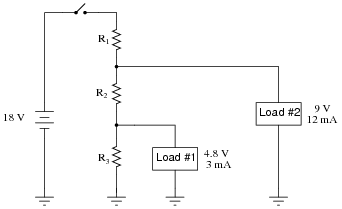
Design a high-voltage divider to provide the following loads with their necessary voltages, plus a "bleeder" current of 5 mA (the amount of current going through resistor R4):
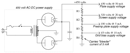
|
|
- R1 = 3.25 kW
- R2 = 11 kW
- R3 = 3.67 kW
- R4 = 9 kW
Notes:
Be sure to ask your students how they obtained the solution to this problem. If no one was able to arrive at a solution, then present the following technique: simplify the problem (fewer resistors, perhaps) until the solution is obvious, then apply the same strategy you used to solve the obvious problem to the more complex versions of the problem, until you have solved the original problem in all its complexity.
Question 37:
Suppose a voltmeter has a range of 0 to 10 volts, and an internal resistance of 100 kW:
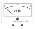
|
|
Show how a single resistor could be connected to this voltmeter to extend its range to 0 to 50 volts. Calculate the resistance of this "range" resistor, as well as its necessary power dissipation rating.
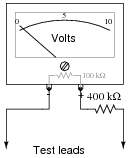
|
|
A power dissipation rating of 1/8 watt would be more than sufficient for this application.
Notes:
Voltmeter ranging is a very practical example of voltage divider circuitry.