Advanced electromagnetism and electromagnetic induction
Question 1:
|
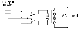
Electronic power conversion circuits known as inverters convert DC into AC by using transistor switching elements to periodically reverse the polarity of the DC voltage. Usually, inverters also increase the voltage level of the input power by applying the switched-DC voltage to the primary winding of a step-up transformer. You may think of an inverter's switching electronics as akin to double-pole, double-throw switch being flipped back and forth many times per second:
|
|
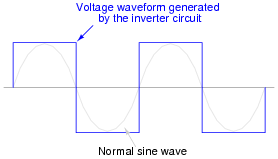
The first commercially available inverters produced simple square-wave output:
|
|
However, this caused problems for most power transformers designed to operate on sine-wave AC power. When powered by the square-wave output of such an inverter, most transformers would saturate due to excessive magnetic flux accumulating in the core at certain points of the waveform's cycle. To describe this in the simplest terms, a square wave possesses a greater volt-second product than a sine wave with the same peak amplitude and fundamental frequency.
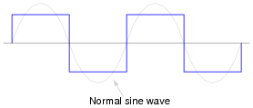
This problem could be avoided by decreasing the peak voltage of the square wave, but then some types of powered equipment would experience difficulty due to insufficient (maximum) voltage:
|
|
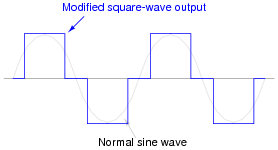
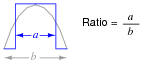
A workable solution to this dilemma turned out to be a modified duty cycle for the square wave:
|
|
Calculate the fraction of the half-cycle for which this modified square wave is ön," in order to have the same volt-second product as a sine wave for one-half cycle (from 0 to p radians):
|
|
Hint: it is a matter of calculating the respective areas underneath each waveform in the half-cycle domain.
Challenge question: prove that the duty cycle fraction necessary for the square wave to have the same RMS value as the sine wave is exactly 1/2. Hint: the volts-squared-second product of the two waveforms must be equal for their RMS values to be equal!
Notes:
This problem is a great example of how integration is used in a very practical sense. Even if your students are unfamiliar with calculus, they should at least be able to grasp the concept of equal volt-second products for the two waveforms, and be able to relate that to the amount of magnetic flux accumulating in the transformer core throughout a cycle.
Question 2:
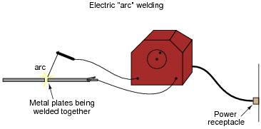
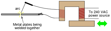
An electric arc welder is a power conversion device, used to step utility power voltage (usually 240 or 480 volts AC) down to a low voltage, and conversely step up the current (to 100 amps or more), to generate a very hot arc used to weld metal pieces together:
|
|
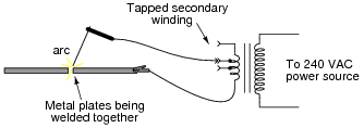
The simplest designs of arc welder are nothing more than a large step-down transformer. To achieve different power intensities for welding different thicknesses of metal, some of these arc welders are equipped with taps on the secondary winding:
|
|
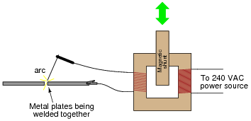
Some arc welder designs achieve continuous variability by moving a magnetic ßhunt" in and out of the transformer core structure:
|
|
Explain how this shunt works. Which way does it need to be moved in order to increase the intensity of the welding arc? What advantages does this method of arc power control have over a "tapped" secondary winding?
Challenge question: why would it not be a good idea to achieve the same continuously-variable arc control by varying the reluctance (�) of the transformer's magnetic circuit, like this?
|
|
Notes:
This question illustrates an application of the coupling (k) factor between mutual inductors. There are a few advantages of controlling the arc welder's output in this manner, as compared to using winding taps, so be sure to discuss this with your students.
As to the challenge question, controlling the transformer output in this manner would also affect the magnetizing inductance of the primary winding, which would have detrimental effects at low settings (what would happen to the ëxcitation" current of the primary winding as its inductance decreases?).
Question 3:
The majority of the "humming" sound emitted by an unloaded transformer is due to an effect known as magnetostriction. What is this effect, exactly?
Notes:
Ask your students if they discovered whether magnetostrictive materials normally contract or expand with the application of a magnetic field. The answer to this question is quite surprising!
Question 4:
|
What would happen to the magnetic flux inside an air-core inductor made of superconducting wire (no electrical resistance at all), if a constant DC voltage were applied to that coil? Remember, this is an ideal scenario, where the only mathematical function describing the resulting flux is that which relates magnetic flux to voltage and time!
Follow-up question: what would happen with an iron-cored inductor, with the same superconducting (zero-resistance) wire?
Notes:
Discuss with your students why the flux increases linearly, as described by Faraday's Law of electromagnetic induction. When discussing the iron-core scenario, be sure to mention magnetic saturation if your students have not considered it!
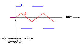
Question 5:
|
�f(x) dx Calculus alert! |
|
|
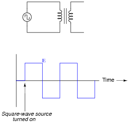
Hint: The output voltage (measured at the secondary winding) will also be a square wave, perfectly in-phase with the source (primary) voltage.
|
|
Notes:
Have students relate the equation EL = N [(d f)/dt] to this problem, discussing the flux wave-shape in terms of rate-of-change over time.
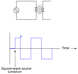
Question 6:
|
�f(x) dx Calculus alert! |
|
|
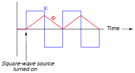
Hint: The output voltage (measured at the secondary winding) will also be a square wave, perfectly in-phase with the source (primary) voltage.
|
|
Notes:
Have students relate the equation EL = N [(d f)/dt] to this problem, discussing the flux wave-shape in terms of rate-of-change over time.
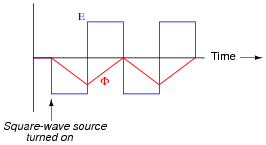
Question 7:
|
�f(x) dx Calculus alert! |
|
|
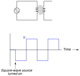
Important: note the point in time where the square-wave source is energized. The first pulse of applied voltage to the primary winding is not full-duration!
|
|
Follow-up question: explain why the flux waveform is symmetrical about the zero line (perfectly balanced between positive and negative half-cycles) in this particular scenario. How would this situation differ if the square-wave voltage source were energized at a slightly different point in time?
Notes:
Have students relate the equation EL = N [(d f)/dt] to this problem, discussing the flux wave-shape in terms of rate-of-change over time.
Question 8:
Power transformers may ßurge" when initially connected to a source of AC voltage, drawing up to several times their rated primary current for a brief period of time. This inrush of current is usually audible, especially if the transformer is a large power distribution unit, and you happen to be standing next to it!
At first, this phenomenon may seem contradictory, based on your knowledge of how inductances respond to transient DC voltage (zero current at first, then the current builds asymptotically to its maximum value). Indeed, even with AC, it is the nature of inductance to oppose current by dropping voltage (producing a counter-EMF). So why would an unloaded transformer draw a large inrush current when initially connected to a source of AC voltage?
Hint: a transformer will not always surge when first connected to its voltage source. In fact, if you were to open and close the disconnect switch feeding a power transformer's primary winding, you would find the surge phenomenon to be almost random: some times there would be no surge when you closed the switch, and other times there would be surge (to varying degrees) when the switch closed.
Notes:
This is a complex question to answer. A full explanation of the ßurge" effect requires the use of calculus (integrating the voltage waveform over time) to explain the magnitude of magnetic flux in the transformer core, and how this approaches saturation during a surge.
Despite the highly mathematical nature of the question, it is a very practical one. If and when your students build AC-DC power supplies, they may find that the fuse in series with the primary winding of the transformer occasionally blows when powered up, even though the power supply is unloaded at the time, and despite the fact that the fuse does not blow when the power supply is fully loaded. What causes this random blowing of fuses? Transformer surge!
Question 9:
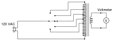
Suppose you were testing this step-down transformer, moving the selector switch between its various positions and measuring the transformer's output voltage at each switch position:
|
|
You notice something strange: when the switch is moved to the position producing the greatest output voltage, the transformer audibly "buzzes." It produces no noticeable noise in any of the other switch positions. Why is this happening?
Hint: if the switch is left in the "buzzing" position for any substantial amount of time, the transformer temperature begins to increase.
Notes:
Discuss with your students why the transformer core saturates only in that one switch position. Why not in any of the other switch positions?
In a non-tapped transformer, what condition(s) lead to core saturation? How does this relate to the scenario shown here with a tapped transformer?
Ideally, power transformer circuits should be designed to avoid core saturation, but this is not always the case in cheap designs. I once encountered a tapped transformer, much like the one shown in the diagram, from an automotive battery charger which acted like this. It was an excellent example for my students to feel and hear magnetic saturation.
Question 10:
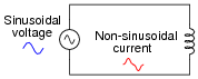
It is a known fact that the nonlinearity of a ferromagnetic material's B-H curve will cause an inductor's current to be non-sinusoidal, even when the voltage impressed across the inductor is perfectly sinusoidal:
|
|
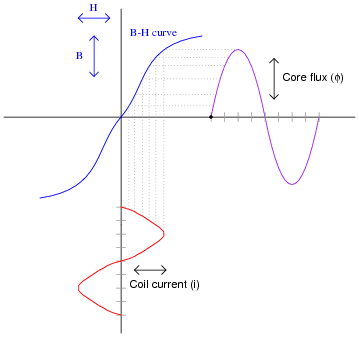
Unless coil resistance is substantial, the core flux waveform (f) over time will be just as sinusoidal as the voltage waveform, because without resistance to drop voltage, the relationship between voltage and flux is e = N[(df)/dt], the rate-of-change of a perfect sine wave being a perfect cosine wave.
Knowing that the core flux waveform will be sinusoidal allows us to derive the inductor current waveform from the B-H curve using a graphical "trick": using the B-H curve to correlate instantaneous values of flux over time with instantaneous values of coil current over time. When used in this manner, the B-H curve is called a transfer characteristic, because it is used as a map to "transfer" points on one waveform to points on another waveform. We know that f is directly proportional to B because B = [(F)/A], and the core area is constant. We also know that i is directly proportional to H, because F = NI and H = [(F)/l], and both the core length and the number of turns of wire are constant:
|
|
Notice that the flux waveform is nice and sinusoidal, while the current waveform is not.
Based on what you see here, describe how an inductor designer can minimize the current distortion in an inductor. What conditions make this distortion better, and what conditions make it worse?
Notes:
I wrote this question for the purpose of introducing students to a technique commonly found in older textbooks, but not found in newer textbooks quite as often: graphically generating a plot by the comparison of one waveform against a static function, in this case the comparison of the flux waveform against the B-H curve. Not only is this technique helpful in analyzing magnetic nonlinearities, but it also works well to analyze semiconductor circuit nonlinearities.
Question 11:
|
Faraday's Law of electromagnetic induction states that the induced voltage across a coil of wire is equal to the number of "turns" in the coil multiplied by the rate of change of magnetic flux over time:
|
Often you will see a negative sign preceding the right-hand side of the equation, to properly denote polarity of the induced voltage. This is the mathematical expression of Lenz's Law. In this equation, though, the negative sign is omitted and we pay attention only to the absolute value of induced voltage.
Use calculus techniques to express f as a function of v, so that we may have an equation useful for predicting the amount of magnetic flux accumulated in an inductor or transformer given the voltage across it (v) and the time of the accumulation (T). Hint: you may treat this as a differential equation with separable variables.
For those who are unfamiliar with calculus, you may still answer this question, albeit in a simpler form: write an equation describing the change in magnetic flux within a coil (DF) given a constant DC voltage across the coil (V) and a certain amount of time (t).
|
If the voltage is constant (V), the change in flux may be calculated by this simple equation:
|
Notes:
Even if students are not familiar with differential equations at all, they should be able to arrive at the second (algebraic) equation if they properly understand how flux rate-of-change relates to induced voltage.