Passive filter circuits
Question 1:
In very simple, qualitative terms, rate the impedance of capacitors and inductors as ßeen" by low-frequency and high-frequency signals alike:
- �
- Capacitor as it äppears" to a low frequency signal: (high or low) impedance?
- �
- Capacitor as it äppears" to a high frequency signal: (high or low) impedance?
- �
- Inductor as it äppears" to a low frequency signal: (high or low) impedance?
- �
- Inductor as it äppears" to a high frequency signal: (high or low) impedance?
- �
- Capacitor as it äppears" to a low frequency signal: high impedance.
- �
- Capacitor as it äppears" to a high frequency signal: low impedance.
- �
- Inductor as it äppears" to a low frequency signal: low impedance.
- �
- Inductor as it äppears" to a high frequency signal: high impedance.
Challenge question: what does a capacitor äppear" as to a DC signal?
Notes:
Ask your students how they arrived at their answers for these qualitative assessments. If they found difficulty understanding the relationship of frequency to impedance for reactive components, I suggest you work through the reactance equations qualitatively with them. In other words, evaluate each of the reactance formulae (XL = 2 pf L and XC = [1/(2 pf C)]) in terms of f increasing and decreasing, to understand how each of these components reacts to low- and high-frequency signals.
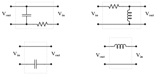
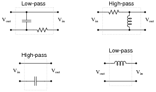
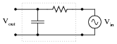
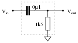
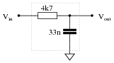
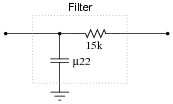
Question 2:
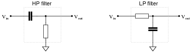
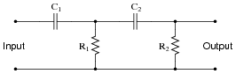
Identify these filters as either being "low-pass" or "high-pass", and be prepared to explain your answers:
|
|
|
|
Notes:
Low-pass and high-pass filter circuit are really easy to identify if you consider the input frequencies in terms of extremes: radio frequency (very high), and DC (f = 0 Hz). Ask your students to identify the respective impedances of all components in a filter circuit for these extreme frequency examples, and the functions of each filter circuit should become very clear to see.
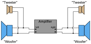
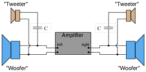
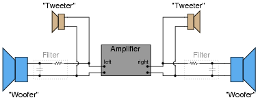
Question 3:
Suppose you were installing a high-power stereo system in your car, and you wanted to build a simple filter for the "tweeter" (high-frequency) speakers so that no bass (low-frequency) power is wasted in these speakers. Modify the schematic diagram below with a filter circuit of your choice:
|
|
Hint: this only requires a single component per tweeter!
|
|
Follow-up question: what type of capacitor would you recommend using in this application (electrolytic, mylar, ceramic, etc.)? Why?
Notes:
Ask your students to describe what type of filter circuit a series-connected capacitor forms: low-pass, high-pass, band-pass, or band-stop? Discuss how the name of this filter should describe its intended function in the sound system.
Regarding the follow-up question, it is important for students to recognize the practical limitations of certain capacitor types. One thing is for sure, ordinary (polarized) electrolytic capacitors will not function properly in an application like this!
Question 4:
It is common in audio systems to connect a capacitor in series with each "tweeter" (high-frequency) speaker to act as a simple high-pass filter. The choice of capacitors for this task is important in a high-power audio system.
A friend of mine once had such an arrangement for the tweeter speakers in his car. Unfortunately, though, the capacitors kept blowing up when he operated the stereo at full volume! Tired of replacing these non-polarized electrolytic capacitors, he came to me for advice. I suggested he use mylar or polystyrene capacitors instead of electrolytics. These were a bit more expensive than electrolytic capacitors, but they did not blow up. Explain why.
Notes:
Your students may have to do a bit of refreshing (or first-time research!) on the meaning of ESR before they can understand why large ESR values could cause a capacitor to explode under extreme operating conditions.
Question 5:
Suppose a friend wanted to install filter networks in the "woofer" section of their stereo system, to prevent high-frequency power from being wasted in speakers incapable of reproducing those frequencies. To this end, your friend installs the following resistor-capacitor networks:
|
|
After examining this schematic, you see that your friend has the right idea in mind, but implemented it incorrectly. These filter circuits would indeed block high-frequency signals from getting to the woofers, but they would not actually accomplish the stated goal of minimizing wasted power.
What would you recommend to your friend in lieu of this circuit design?
Notes:
The reason for this choice in filter designs is very practical. Ask your students to describe how a ßhunting" form of filter works, where the reactive component is connected in parallel with the load, receiving power through a series resistor. Contrast this against a "blocking" form of filter circuit, in which a reactive component is connected in series with the load. In one form of filter, a resistor is necessary. In the other form of filter, a resistor is not necessary. What difference does this make in terms of power dissipation within the filter circuit?
Question 6:
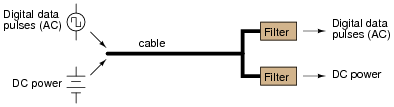
The superposition principle describes how AC signals of different frequencies may be "mixed" together and later separated in a linear network, without one signal distorting another. DC may also be similarly mixed with AC, with the same results.
This phenomenon is frequently exploited in computer networks, where DC power and AC data signals (on-and-off pulses of voltage representing 1-and-0 binary bits) may be combined on the same pair of wires, and later separated by filter circuits, so that the DC power goes to energize a circuit, and the AC signals go to another circuit where they are interpreted as digital data:
|
|
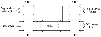
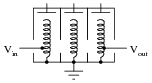
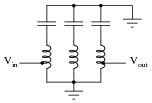
Filter circuits are also necessary on the transmission end of the cable, to prevent the AC signals from being shunted by the DC power supply's capacitors, and to prevent the DC voltage from damaging the sensitive circuitry generating the AC voltage pulses.
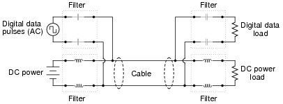
Draw some filter circuits on each end of this two-wire cable that perform these tasks, of separating the two sources from each other, and also separating the two signals (DC and AC) from each other at the receiving end so they may be directed to different loads:
|
|
|
|
Follow-up question #1: how might the superposition theorem be applied to this circuit, for the purposes of analyzing its function?
Follow-up question #2: suppose one of the capacitors were to fail shorted. Identify what effect, if any, this would have on the operation of the circuit. What if two capacitors were to fail shorted? Would it matter if those two capacitors were both on either the transmitting or the receiving side, or if one of the failed capacitors was on the transmitting side and the other was on the receiving side?
Notes:
Discuss with your students why inductors were chosen as filtering elements for the DC power, while capacitors were chosen as filtering elements for the AC data signals. What are the relative reactances of these components when subjected to the respective frequencies of the AC data signals (many kilohertz or megahertz) versus the DC power supply (frequency = 0 hertz).
This question is also a good review of the ßuperposition theorem," one of the most useful and easiest-to-understand of the network theorems. Note that no quantitative values need be considered to grasp the function of this communications network. Analyze it qualitatively with your students instead.
Question 7:
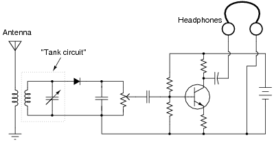
The following schematic shows the workings of a simple AM radio receiver, with transistor amplifier:
|
|
The "tank circuit" formed of a parallel-connected inductor and capacitor network performs a very important filtering function in this circuit. Describe what this filtering function is.
Follow-up question: how might a variable capacitor be constructed, to suit the needs of a circuit such as this? Note that the capacitance range for a tuning capacitor such as this is typically in the pico-Farad range.
Notes:
Challenge your students to describe how to change stations on this radio receiver. For example, if we are listening to a station broadcasting at 1000 kHz and we want to change to a station broadcasting at 1150 kHz, what do we have to do to the circuit?
Be sure to discuss with them the construction of an adjustable capacitor (air dielectric).
Question 8:
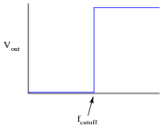
Draw the Bode plot for an ideal high-pass filter circuit:

|
|
Be sure to note the "cutoff frequency" on your plot.
|
|
Follow-up question: a theoretical filter with this kind of idealized response is sometimes referred to as a "brick wall" filter. Explain why this name is appropriate.
Notes:
The plot given in the answer, of course, is for an ideal high-pass filter, where all frequencies below fcutoff are blocked and all frequencies above fcutoff are passed. In reality, filter circuits never attain this ideal ßquare-edge" response. Discuss possible applications of such a filter with your students.
Challenge them to draw the Bode plots for ideal band-pass and band-stop filters as well. Exercises such as this really help to clarify the purpose of filter circuits. Otherwise, there is a tendency to lose perspective of what real filter circuits, with their correspondingly complex Bode plots and mathematical analyses, are supposed to do.
Question 9:
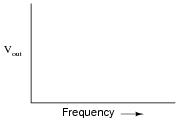
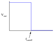
Draw the Bode plot for an ideal low-pass filter circuit:
|
|
Be sure to note the "cutoff frequency" on your plot.
|
|
Follow-up question: a theoretical filter with this kind of idealized response is sometimes referred to as a "brick wall" filter. Explain why this name is appropriate.
Notes:
The plot given in the answer, of course, is for an ideal low-pass filter, where all frequencies below fcutoff are passed and all frequencies above fcutoff are blocked. In reality, filter circuits never attain this ideal ßquare-edge" response. Discuss possible applications of such a filter with your students.
Challenge them to draw the Bode plots for ideal band-pass and band-stop filters as well. Exercises such as this really help to clarify the purpose of filter circuits. Otherwise, there is a tendency to lose perspective of what real filter circuits, with their correspondingly complex Bode plots and mathematical analyses, are supposed to do.
Question 10:
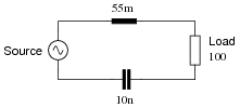
Identify what type of filter this circuit is, and calculate its cutoff frequency given a resistor value of 1 kW and a capacitor value of 0.22 mF:
|
|
Calculate the impedance of both the resistor and the capacitor at this frequency. What do you notice about these two impedance values?
fcutoff = 723.4 Hz
Notes:
Be sure to ask students where they found the cutoff frequency formula for this filter circuit.
When students calculate the impedance of the resistor and the capacitor at the cutoff frequency, they should notice something unique. Ask your students why these values are what they are at the cutoff frequency. Is this just a coincidence, or does this tell us more about how the "cutoff frequency" is defined for an RC circuit?
Question 11:
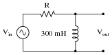
Identify what type of filter this circuit is, and calculate its cutoff frequency:
|
|
fcutoff = 1.061 kHz
Notes:
Be sure to ask students where they found the cutoff frequency formula for this filter circuit.
Question 12:
Identify what type of filter this circuit is, and calculate its cutoff frequency:
|
|
fcutoff = 1.026 kHz
Notes:
Be sure to ask students where they found the cutoff frequency formula for this filter circuit.
Question 13:
Identify what type of filter this circuit is, calculate its cutoff frequency, and distinguish the input terminal from the output terminal:
|
|
fcutoff = 48.23 Hz
The input terminal is on the right, while the output terminal is on the left.
Notes:
Be sure to ask students where they found the cutoff frequency formula for this filter circuit. Also, ask them how they were able to distinguish the input and output terminals. What would happen if these terminals were reversed (i.e. if the input signal were applied to the output terminal)?
Question 14:
The formula for determining the cutoff frequency of a simple LR filter circuit looks substantially different from the formula used to determine cutoff frequency in a simple RC filter circuit. Students new to this subject often resort to memorization to distinguish one formula from the other, but there is a better way.
In simple filter circuits (comprised of one reactive component and one resistor), cutoff frequency is that frequency where circuit reactance equals circuit resistance. Use this simple definition of cutoff frequency to derive both the RC and the LR filter circuit cutoff formulae, where fcutoff is defined in terms of R and either L or C.
|
|
Notes:
This is an exercise in algebraic substitution, taking the formula X = R and introducing f into it by way of substitution, then solving for f. Too many students try to memorize every new thing rather than build their knowledge upon previously learned material. It is surprising how many electrical and electronic formulae one may derive from just a handful of fundamental equations, if one knows how to use algebra.
Some textbooks present the LR cutoff frequency formula like this:
|
If students present this formula, you can be fairly sure they simply found it somewhere rather than derived it using algebra. Of course, this formula is exactly equivalent to the one I give in my answer - and it is good to show the class how these two are equivalent - but the real point of this question is to get your students using algebra as a practical tool in their understanding of electrical theory.
Question 15:
Identify what type of filter this circuit is, and calculate the size of resistor necessary to give it a cutoff frequency of 3 kHz:
|
|
R = 2 pf L
R = 5.65 kW
Notes:
The most important part of this question, as usual, is to have students come up with methods of solution for determining R's value. Ask them to explain how they arrived at their answer, and if their method of solution made use of any formula or principle used in capacitive filter circuits.
Question 16:
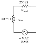
Calculate the power dissipated by this circuit's load at two different source frequencies: 0 Hz (DC), and fcutoff.
|
|
What do these figures tell you about the nature of this filter circuit (whether it is a low-pass or a high-pass filter), and also about the definition of cutoff frequency (also referred to as f-3 dB)?
Pload @ fcutoff = 32 mW
These load dissipation figures prove this circuit is a low-pass filter. They also demonstrate that the load dissipation at fcutoff is exactly half the amount of power the filter is capable of passing to the load under ideal (maximum) conditions.
Notes:
If your students have never encountered decibel (dB) ratings before, you should explain to them that -3 dB is an expression meaning öne-half power," and that this is why the cutoff frequency of a filter is often referred to as the half-power point.
The important lesson to be learned here about cutoff frequency is that its definition means something in terms of load power. It is not as though someone decided to arbitrarily define fcutoff as the point at which the load receives 70.7% of the source voltage!
Question 17:
Filter circuits don't just attenuate signals, they also shift the phase of signals. Calculate the amount of phase shift that these two filter circuits impart to their signals (from input to output) operating at the cutoff frequency:
|
|
LP filter: Q = -45o (Vout lags Vin)
Notes:
Note that no component values are given in this question, only the condition that both circuits are operating at the cutoff frequency. This may cause trouble for some students, because they are only comfortable with numerical calculations. The structure of this question forces students to think a bit differently than they might be accustomed to.
Question 18:
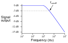
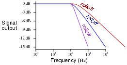
Real filters never exhibit perfect ßquare-edge" Bode plot responses. A typical low-pass filter circuit, for example, might have a frequency response that looks like this:
|
|
What does the term rolloff refer to, in the context of filter circuits and Bode plots? Why would this parameter be important to a technician or engineer?
|
|
Notes:
Point students' attention to the scale used on this particular Bode plot. This is called a log-log scale, where neither vertical nor horizontal axis is linearly marked. This scaling allows a very wide range of conditions to be shown on a relatively small plot, and is very common in filter circuit analysis.
Question 19:
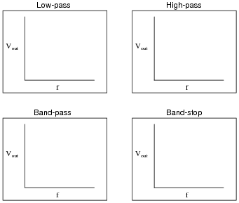
Explain what a band-pass filter is, and how it differs from either a low-pass or a high-pass filter circuit. Also, explain what a band-stop filter is, and draw Bode plots representative of both band-pass and band-stop filter types.
Challenge question: what type of filter, band-pass or band-stop, do you suppose is used in a radio receiver (tuner)? Explain your reasoning.
Notes:
In this question, I've opted to let students draw Bode plots, only giving them written descriptions of each filter type.
Question 20:
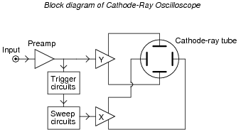
A common way of representing complex electronic systems is the block diagram, where specific functional sections of a system are outlined as squares or rectangles, each with a certain purpose and each having input(s) and output(s). For an example, here is a block diagram of an analog ("Cathode Ray") oscilloscope, or CRO:
|
|
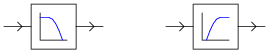
Block diagrams may also be helpful in representing and understanding filter circuits. Consider these symbols, for instance:
|
|
Which of these represents a low-pass filter, and which represents a high-pass filter? Explain your reasoning.
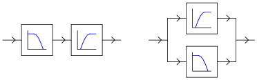
Also, identify the new filter functions created by the compounding of low- and high-pass filter "blocks":
|
|
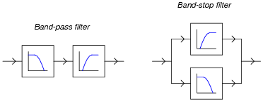
|
|
Notes:
Aside from getting students to understand that band-function filters may be built from sets of low- and high-pass filter blocks, this question is really intended to initiate problem-solving activity. Discuss with your students how they might approach a problem like this to see how the circuits respond. What "thought experiments" did they try in their minds to investigate these circuits?
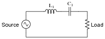
Question 21:
What kind of filtering action (high-pass, low-pass, band-pass, band-stop) does this resonant circuit provide?
|
|
Notes:
As usual, ask your students to explain why the answer is correct, not just repeat the answer that is given!
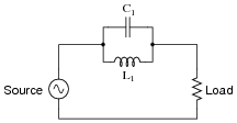
Question 22:
What kind of filtering action (high-pass, low-pass, band-pass, band-stop) does this resonant circuit provide?
|
|
Notes:
As usual, ask your students to explain why the answer is correct, not just repeat the answer that is given!
Question 23:
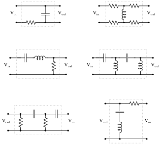
Identify each of these filter types, and explain how you were able to positively identify their behaviors:
|
|
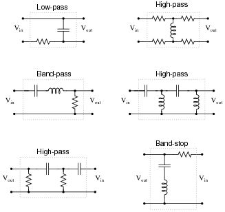
|
|
Follow-up question: in each of the circuits shown, identify at least one single component failure that has the ability to prevent any signal voltage from reaching the output terminals.
Notes:
Some of these filter designs are resonant in nature, while others are not. Resonant circuits, especially when made with high-Q components, approach ideal band-pass (or -block) characteristics. Discuss with your students the different design strategies between resonant and non-resonant band filters.
The high-pass filter containing both inductors and capacitors may at first appear to be some form of resonant (i.e. band-pass or band-stop) filter. It actually will resonate at some frequency(ies), but its overall behavior is still high-pass. If students ask about this, you may best answer their queries by using computer simulation software to plot the behavior of a similar circuit (or by suggesting they do the simulation themselves).
Regarding the follow-up question, it would be a good exercise to discuss which suggested component failures are more likely than others, given the relatively likelihood for capacitors to fail shorted and inductors and resistors to fail open.
Question 24:
Identify the following filter types, and be prepared to explain your answers:
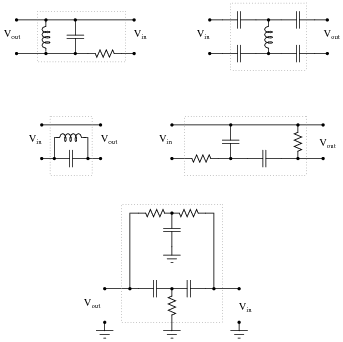
|
|
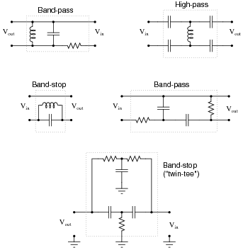
|
|
Notes:
Some of these filter designs are resonant in nature, while others are not. Resonant circuits, especially when made with high-Q components, approach ideal band-pass (or -block) characteristics. Discuss with your students the different design strategies between resonant and non-resonant band filters.
Although resonant band filter designs have nearly ideal (theoretical) characteristics, band filters built with capacitors and resistors only are also popular. Ask your students why this might be. Is there any reason inductors might purposefully be avoided when designing filter circuits?
Question 25:
The cutoff frequency, also known as half-power point or -3dB point, of either a low-pass or a high-pass filter is fairly easy to define. But what about band-pass and band-stop filter circuits? Does the concept of a "cutoff frequency" apply to these filter types? Explain your answer.
Notes:
This question presents a good opportunity to ask students to draw the Bode plot of a typical band-pass or band-stop filter on the board in front of the class to illustrate the concept. Don't be afraid to let students up to the front of the classroom to present their findings. It's a great way to build confidence in them and also to help suppress the illusion that you (the teacher) are the Supreme Authority of the classroom!
Question 26:
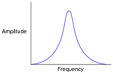
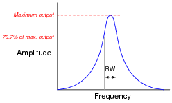
Plot the typical response of a band-pass filter circuit, showing signal output (amplitude) on the vertical axis and frequency on the horizontal axis:
|
|
Also, identify and label the bandwidth of the circuit on your filter plot.
|
|
The bandwidth of a band-pass filter circuit is that range of frequencies where the output amplitude is at least 70.7% of maximum:
|
|
Notes:
Bandwidth is an important concept in electronics, for more than just filter circuits. Your students may discover references to bandwidth of amplifiers, transmission lines, and other circuit elements as they do their research. Despite the many and varied applications of this term, the principle is fundamentally the same.
Question 27:
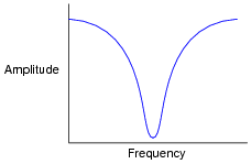
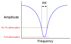
Plot the typical response of a band-stop filter circuit, showing signal output (amplitude) on the vertical axis and frequency on the horizontal axis:

|
|
Also, identify and label the bandwidth of the circuit on your filter plot.
|
|
The bandwidth of a band-stop filter circuit is that range of frequencies where the output amplitude is reduced to at least 70.7% of full attenuation:
|
|
Notes:
Bandwidth is an important concept in electronics, for more than just filter circuits. Your students may discover references to bandwidth of amplifiers, transmission lines, and other circuit elements as they do their research. Despite the many and varied applications of this term, the principle is fundamentally the same.
Question 28:
Plot the typical frequency responses of four different filter circuits, showing signal output (amplitude) on the vertical axis and frequency on the horizontal axis:
|
|
Also, identify and label the bandwidth of the filter circuit on each plot.
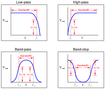
|
|
Notes:
Although "bandwidth" is usually applied first to band-pass and band-stop filters, students need to realize that it applies to the other filter types as well. This question, in addition to reviewing the definition of bandwidth, also reviews the definition of cutoff frequency. Ask your students to explain where the 70.7% figure comes from. Hint: half-power point!
Question 29:
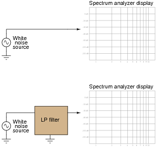
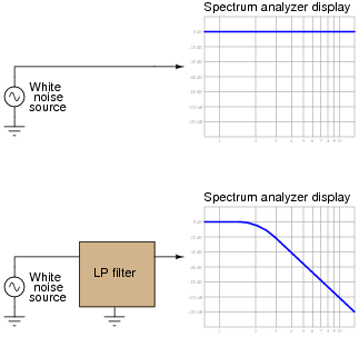
A white noise source is a special type of AC signal voltage source which outputs a broad band of frequencies ("noise") with a constant amplitude across its rated range. Determine what the display of a spectrum analyzer would show if directly connected to a white noise source, and also if connected to a low-pass filter which is in turn connected to a white noise source:
|
|
|
|
Notes:
The purpose of this question, besides providing a convenient way to characterize a filter circuit, is to introduce students to the concept of a white noise source and also to strengthen their understanding of a spectrum analyzer's function.
In case anyone happens to notice, be aware that the rolloff shown for this filter circuit is very steep! This sort of sharp response could never be realized with a simple one-resistor, one-capacitor ("first order") filter. It would have to be a multi-stage analog filter circuit or some sort of active filter circuit.
Question 30:
Predict how the operation of this second-order passive filter circuit will be affected as a result of the following faults. Consider each fault independently (i.e. one at a time, no multiple faults):
|
|
- �
- Capacitor C1 fails open:
- �
- Capacitor C2 fails shorted:
- �
- Resistor R1 fails open:
- �
- Resistor R2 fails open:
- �
- Solder bridge (short) across resistor R2:
For each of these conditions, explain why the resulting effects will occur.
- �
- Capacitor C1 fails open: No output signal at all.
- �
- Capacitor C2 fails shorted: The circuit becomes a first-order filter with fcutoff = [(R1 + R2)/(2 pR1 R2 C)].
- �
- Resistor R1 fails open: The circuit becomes a first-order filter with fcutoff = [(C1 + C2)/(2 pR2 C1 C2)].
- �
- Resistor R2 fails open: The circuit becomes a first-order filter with fcutoff = [1/(2 pR1 C1)] (assuming no load on the output).
- �
- Solder bridge (short) across resistor R2: No output signal at all.
Notes:
The purpose of this question is to approach the domain of circuit troubleshooting from a perspective of knowing what the fault is, rather than only knowing what the symptoms are. Although this is not necessarily a realistic perspective, it helps students build the foundational knowledge necessary to diagnose a faulted circuit from empirical data. Questions such as this should be followed (eventually) by other questions asking students to identify likely faults based on measurements.
Question 31:
The Q factor of a series inductive circuit is given by the following equation:
|
Likewise, we know that inductive reactance may be found by the following equation:
|
We also know that the resonant frequency of a series LC circuit is given by this equation:
|
Through algebraic substitution, write an equation that gives the Q factor of a series resonant LC circuit exclusively in terms of L, C, and R, without reference to reactance (X) or frequency (f).
|
Notes:
This is merely an exercise in algebra. However, knowing how these three component values affects the Q factor of a resonant circuit is a valuable and practical insight!
Question 32:
Calculate the resonant frequency, bandwidth, and half-power points of the following filter circuit:
|
|
Bandwidth = 289.4 Hz
f1 = 6.64 kHz
f2 = 6.93 kHz
Follow-up question: how would a decrease in the Q ("quality factor") of the circuit affect the bandwidth, or would it at all?
Notes:
The formulae required to calculate these parameters are easily obtained from any basic electronics text. No student should have trouble finding this information.
Question 33:
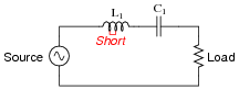
Suppose a few turns of wire within the inductor in this filter circuit suddenly became short-circuited, so that the inductor effectively has fewer turns of wire than it did before:
|
|
What sort of effect would this fault have on the filtering action of this circuit?
Challenge question: what would happen to the Q of this filter circuit as a result of the fault within the inductor?
Notes:
Determining the effect on resonant frequency is a simple matter of qualitative analysis with the resonant frequency formula. The effect on Q (challenge question) may be answered just as easily if the students know the formula relating bandwidth to L, C, and R.
Question 34:
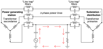
An interesting technology dating back at least as far as the 1940's, but which is still of interest today is power line carrier: the ability to communicate information as well as electrical power over power line conductors. Hard-wired electronic data communication consists of high-frequency, low voltage AC signals, while electrical power is low-frequency, high-voltage AC. For rather obvious reasons, it is important to be able to separate these two types of AC voltage quantities from entering the wrong equipment (especially the high-voltage AC power from reaching sensitive electronic communications circuitry).
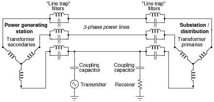
Here is a simplified diagram of a power-line carrier system:
|
|
The communications transmitter is shown in simplified form as an AC voltage source, while the receiver is shown as a resistor. Though each of these components is much more complex than what is suggested by these symbols, the purpose here is to show the transmitter as a source of high-frequency AC, and the receiver as a load of high-frequency AC.
Trace the complete circuit for the high-frequency AC signal generated by the "Transmitter" in the diagram. How many power line conductors are being used in this communications circuit? Explain how the combination of "line trap" LC networks and "coupling" capacitors ensure the communications equipment never becomes exposed to high-voltage electrical power carried by the power lines, and visa-versa.
|
|
Follow-up question #1: trace the path of line-frequency (50 Hz or 60 Hz) load current in this system, identifying which component of the line trap filters (L or C) is more important to the passage of power to the load. Remember that the line trap filters are tuned to resonate at the frequency of the communication signal (50-150 kHz is typical).
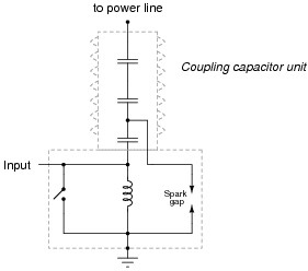
Follow-up question #2: coupling capacitor units used in power line carrier systems are special-purpose, high-voltage devices. One of the features of a standard coupling capacitor unit is a spark gap intended to "clamp" overvoltages arising from lightning strikes and other transient events on the power line:
|
|
Explain how such a spark gap is supposed to work, and why it functions as an over-voltage protection device.
Notes:
Although power line carrier technology is not used as much for communication in high-voltage distribution systems as it used to be - now that microwave, fiber optic, and satellite communications technology has superseded this older technique - it is still used in lower voltage power systems including residential (home) wiring. Ask your students if they have heard of any consumer technology capable of broadcasting any kind of data or information along receptacle wiring. "X10" is a mature technology for doing this, and at this time (2004) there are devices available on the market allowing one to plug telephones into power receptacles to link phones in different rooms together without having to add special telephone cabling.
Even if your students have not yet learned about three-phase power systems or transformers, they should still be able to discern the circuit path of the communications signal, based on what they know of capacitors and inductors, and how they respond to signals of arbitrarily high frequency.
Information on the coupling capacitor units was obtained from page 452 of the Industrial Electronics Reference Book, published by John Wiley & Sons in 1948 (fourth printing, June 1953). Although power line carrier technology is not as widely used now as it was back then, I believe it holds great educational value to students just learning about filter circuits and the idea of mixing signals of differing frequency in the same circuit.
Question 35:
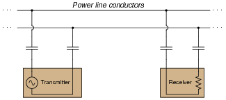
In this power-line carrier system, a pair of coupling capacitors connects a high-frequency "Transmitter" unit to two power line conductors, and a similar pair of coupling capacitors connects a "Receiver" unit to the same two conductors:
|
|
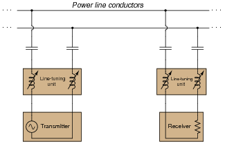
While coupling capacitors alone are adequate to perform the necessary filtering function needed by the communications equipment (to prevent damaged from the high-voltage electrical power also carried by the lines), that signal coupling may be made more efficient by the introduction of two line tuning units:
|
|
Explain why the addition of more components (in series, no less!) provides a better "connection" between the high-frequency Transmitter and Receiver units than coupling capacitors alone. Hint: the operating frequency of the communications equipment is fixed, or at least variable only over a narrow range.
Challenge question: there are many applications in electronics where we couple high-frequency AC signals by means of capacitors alone. If capacitive reactance is any concern, we just use capacitors of large enough value that the reactance is minimal. Why would this not be a practical option in a power-line carrier system such as this? Why could we not (or why would we not) just choose coupling capacitors with very high capacitances, instead of adding extra components to the system?
Notes:
Although power line carrier technology is not used as much for communication in high-voltage distribution systems as it used to be - now that microwave, fiber optic, and satellite communications technology has come of age - it is still used in lower voltage power systems including residential (home) wiring. Ask your students if they have heard of any consumer technology capable of broadcasting any kind of data or information along receptacle wiring. "X10" is a mature technology for doing this, and at this time (2004) there are devices available on the market allowing one to plug telephones into power receptacles to link phones in different rooms together without having to add special telephone cabling.
I think this is a really neat application of resonance: the complementary nature of inductors to capacitors works to overcome the less-than-ideal coupling provided by capacitors alone. Discuss the challenge question with your students, asking them to consider some of the practical limitations of capacitors, and how an inductor/capacitor resonant pair solves the line-coupling problem better than an oversized capacitor.
Question 36:
The following circuit is called a twin-tee filter:
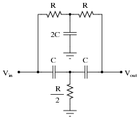
|
|
Research the equation predicting this circuit's "notch" frequency, given the component value ratios shown.
|
|
Notes:
Answering this question is simply a matter of research! There are many references a student could go to for information on twin-tee filters.
Question 37:
Suppose this band-stop filter were to suddenly start acting as a high-pass filter. Identify a single component failure that could cause this problem to occur:
|
|
Notes:
Ask your students to explain why an open R2 would cause this filter to act as a high-pass instead of a band-stop. Then, ask them to identify other possible component failures that could cause a similar effect.
By the way, this filter circuit illustrates the popular twin-tee filter topology.
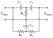
Question 38:
Examine the following schematic diagram for an audio tone control circuit:
|
|
Determine which potentiometer controls the bass (low frequency) tones and which controls the treble (high frequency) tones, and explain how you made those determinations.
|
|
Notes:
The most important answer to this question is how your students arrived at the correct potentiometer identifications. If none of your students were able to figure out how to identify the potentiometers, give them this tip: use the superposition theorem to analyze the response of this circuit to both low-frequency signals and high-frequency signals. Assume that for bass tones the capacitors are opaque (Z = �) and that for treble tones they are transparent (Z = 0). The answers should be clear if they follow this technique.
This general problem-solving technique - analyzing two or more ëxtreme" scenarios to compare the results - is an important one for your students to become familiar with. It is extremely helpful in the analysis of filter circuits!
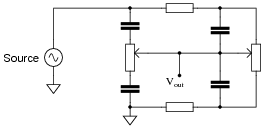
Question 39:
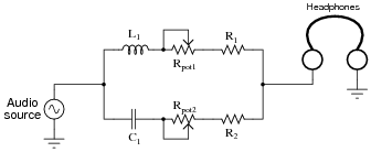
Examine the following audio tone control circuit, used to control the balance of bass and treble heard at the headphones from an audio source such as a radio or CD player:
|
|
Suppose that after working just fine for quite a long while, suddenly no more bass tones were heard through the headphones. Identify at least two component or wiring faults that could cause this to happen.
- �
- R1 failed open
- �
- Rpot1 failed open
- �
- L1 failed open
- �
- Open wire connections between any of the above listed components
Notes:
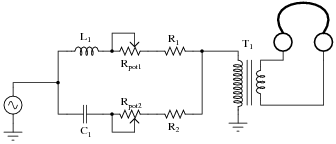
The circuit shown in the question is not very practical for direct headphone use, unless low-value resistors are used. Otherwise, the losses are too great and maximum volume suffers. An improvement over the original circuit is one where a matching transformer is used to effectively increase the impedance of the headphones:
|
|
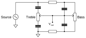
Question 40:
Suppose that the following audio tone control circuit has a problem: the second potentiometer (Rpot2) seems to act more like a plain volume control than a tone control. Instead of adjusting the amount of treble heard at the headphones, it seems to adjust the volume of bass and treble tones alike:

|
|
What do you think might be wrong with this circuit? Assuming it has been correctly designed and was working well for some time, what component or wire failure could possibly account for this behavior?
Notes:
Discuss with your students how this circuit functions before they offer their ideas for faulted components or wires. One must understand the basic operating principle(s) of a circuit before one can troubleshoot it effectively!
Question 41:
Suppose that the following audio tone control circuit has a problem: the first potentiometer (Rpot1) seems to act more like a plain volume control than a tone control. Instead of adjusting the amount of bass heard at the headphones, it seems to adjust the volume of bass and treble tones alike:

|
|
What do you think might be wrong with this circuit? Assuming it has been correctly designed and was working well for some time, what component or wire failure could possibly account for this behavior?
Notes:
Discuss with your students how this circuit functions before they offer their ideas for faulted components or wires. One must understand the basic operating principle(s) of a circuit before one can troubleshoot it effectively!
Question 42:
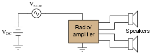
Controlling electrical "noise" in automotive electrical systems can be problematic, as there are many sources of "noise" voltages throughout a car. Spark ignitions and alternators can both generate substantial noise voltages, superimposed on the DC voltage in a car's electrical system. A simple way to electrically model this noise is to draw it as an AC "noise voltage" source in series with the DC source. If this noise enters a radio or audio amplifier, the result will be an irritating sound produced at the speakers:
|
|
What would you suggest as a "fix" for this problem if a friend asked you to apply your electronics expertise to their noisy car audio system? Be sure to provide at least two practical suggestions.
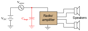
|
|
Other, more sophisticated solutions exist, however!
Follow-up question: use superposition theorem to show why the capacitor mitigates the electrical noise without interfering with the transfer of DC power to the radio/amplifier.
Notes:
The follow-up question is yet another example of how practical the superposition theorem is when analyzing filter circuits.
Question 43:
A helical resonator is a special type of band-pass filter commonly used in VHF and UHF radio receiver circuitry. Such a device is made up of multiple metal cavities, each containing a helix (coil) of wire connected to the cavity at one end and free at the other. Slots cut between the cavities permits coupling between the coils, with the input at one extreme end and the output at the other:
|
|
The above illustration shows a three-stage helical resonator, with adjustable metal plates at the top of each helix for tuning. Draw a schematic representation of this resonator, and explain where the capacitance comes from that allows each of the coils to form a resonant circuit.
|
|
Follow-up question: why do you suppose multiple stages of tuned ("tank") circuits would be necessary in a high-quality tuner circuit? Why not just use a single tank circuit as a filter? Would that not be simpler and less expensive?
Notes:
If students have a difficult time seeing where the capacitance comes from, remind them that we are dealing with very high frequencies here, and that air between metal parts is a sufficient dielectric to create the needed capacitance.
The coupling between coils may be a bit more difficult to grasp, especially if your students have not yet studied mutual inductance. Suffice it to say that energy is transferred between coils with little loss at high frequencies, permitting an RF signal to enter at one end of the resonator and exit out the other without any wires physically connecting the stages together.
Question 44:
| Don't just sit there! Build something!! |
Learning to mathematically analyze circuits requires much study and practice. Typically, students practice by working through lots of sample problems and checking their answers against those provided by the textbook or the instructor. While this is good, there is a much better way.
You will learn much more by actually building and analyzing real circuits, letting your test equipment provide the änswers" instead of a book or another person. For successful circuit-building exercises, follow these steps:
- 1.
- Carefully measure and record all component values prior to circuit construction.
- 2.
- Draw the schematic diagram for the circuit to be analyzed.
- 3.
- Carefully build this circuit on a breadboard or other convenient medium.
- 4.
- Check the accuracy of the circuit's construction, following each wire to each connection point, and verifying these elements one-by-one on the diagram.
- 5.
- Mathematically analyze the circuit, solving for all voltage and current values.
- 6.
- Carefully measure all voltages and currents, to verify the accuracy of your analysis.
- 7.
- If there are any substantial errors (greater than a few percent), carefully check your circuit's construction against the diagram, then carefully re-calculate the values and re-measure.
For AC circuits where inductive and capacitive reactances (impedances) are a significant element in the calculations, I recommend high quality (high-Q) inductors and capacitors, and powering your circuit with low frequency voltage (power-line frequency works well) to minimize parasitic effects. If you are on a restricted budget, I have found that inexpensive electronic musical keyboards serve well as "function generators" for producing a wide range of audio-frequency AC signals. Be sure to choose a keyboard "voice" that closely mimics a sine wave (the "panflute" voice is typically good), if sinusoidal waveforms are an important assumption in your calculations.
As usual, avoid very high and very low resistor values, to avoid measurement errors caused by meter "loading". I recommend resistor values between 1 kW and 100 kW.
One way you can save time and reduce the possibility of error is to begin with a very simple circuit and incrementally add components to increase its complexity after each analysis, rather than building a whole new circuit for each practice problem. Another time-saving technique is to re-use the same components in a variety of different circuit configurations. This way, you won't have to measure any component's value more than once.
Notes:
It has been my experience that students require much practice with circuit analysis to become proficient. To this end, instructors usually provide their students with lots of practice problems to work through, and provide answers for students to check their work against. While this approach makes students proficient in circuit theory, it fails to fully educate them.
Students don't just need mathematical practice. They also need real, hands-on practice building circuits and using test equipment. So, I suggest the following alternative approach: students should build their own "practice problems" with real components, and try to mathematically predict the various voltage and current values. This way, the mathematical theory "comes alive," and students gain practical proficiency they wouldn't gain merely by solving equations.
Another reason for following this method of practice is to teach students scientific method: the process of testing a hypothesis (in this case, mathematical predictions) by performing a real experiment. Students will also develop real troubleshooting skills as they occasionally make circuit construction errors.
Spend a few moments of time with your class to review some of the "rules" for building circuits before they begin. Discuss these issues with your students in the same Socratic manner you would normally discuss the worksheet questions, rather than simply telling them what they should and should not do. I never cease to be amazed at how poorly students grasp instructions when presented in a typical lecture (instructor monologue) format!
An excellent way to introduce students to the mathematical analysis of real circuits is to have them first determine component values (L and C) from measurements of AC voltage and current. The simplest circuit, of course, is a single component connected to a power source! Not only will this teach students how to set up AC circuits properly and safely, but it will also teach them how to measure capacitance and inductance without specialized test equipment.
A note on reactive components: use high-quality capacitors and inductors, and try to use low frequencies for the power supply. Small step-down power transformers work well for inductors (at least two inductors in one package!), so long as the voltage applied to any transformer winding is less than that transformer's rated voltage for that winding (in order to avoid saturation of the core).
A note to those instructors who may complain about the "wasted" time required to have students build real circuits instead of just mathematically analyzing theoretical circuits:
What is the purpose of students taking your course?
If your students will be working with real circuits, then they should learn on real circuits whenever possible. If your goal is to educate theoretical physicists, then stick with abstract analysis, by all means! But most of us plan for our students to do something in the real world with the education we give them. The "wasted" time spent building real circuits will pay huge dividends when it comes time for them to apply their knowledge to practical problems.
Furthermore, having students build their own practice problems teaches them how to perform primary research, thus empowering them to continue their electrical/electronics education autonomously.
In most sciences, realistic experiments are much more difficult and expensive to set up than electrical circuits. Nuclear physics, biology, geology, and chemistry professors would just love to be able to have their students apply advanced mathematics to real experiments posing no safety hazard and costing less than a textbook. They can't, but you can. Exploit the convenience inherent to your science, and get those students of yours practicing their math on lots of real circuits!