Electron versus Conventional flow
Question 1:
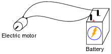
In this electrical circuit, trace the direction of current through the wires:
|
|
Notes:
This question breaches one of the more contentious subjects in electricity/electronics: which way do we denote the direction of current? While there is no debate as to which direction electrons move through a metal conductor carrying current, there are two different conventions for denoting current travel, one of which goes in the direction of electrons and the other which goes against the direction of electrons. The reason for having these two disparate conventions is embedded in the history of electrical science, and what your students find in their research will likely fuel an interesting conversation.
Question 2:
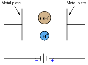
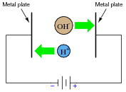
Show which directions these free-floating ions would move, if exposed to an electric field of the polarity shown:
|
|
Note: the "H+" ion is a positively charged hydrogen atom, while the ÖH-" ion is a negatively charged hydroxyl ion.
|
|
Follow-up question: which of these metal plates would we call the cathode, and which would we call the anode?
Notes:
The scenario shown is not academic - it is what happens when an electric field is applied to water. The dissociated ions move in opposite directions, liberating hydrogen gas at the negative electrode and oxygen gas at the positive.
Question 3:
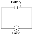
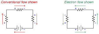
Label the directions of both electron flow and conventional flow in this simple circuit:
|
|

|
|
Notes:
In case anyone asks, the little circles with the letter ë" inside are supposed to represent electrons. Kind of silly, I know, but I was looking for some way of clearly distinguishing one direction from the other without just relying on the text labels.
Question 4:
In metallic conductors, the dominant carriers of electric charge are free electrons, which of course are negatively charged. Are there any examples of electric conduction where electric charge is carried by positively-charged particles?
Notes:
Other examples exist, so do not accept the given answer as the only answer!
Note: some students may suggest holes in semiconductors as an example of positive charge-carriers. This is technically not true, though. A "hole" does not exist as a real particle of matter. It is an abstraction, used by solid-state physicists and engineers to differentiate conduction-band electron motion (ëlectrons") from valence-band electron motion ("holes").
Question 5:
Explain, in your own words, how we came to have two completely opposite notations for labeling the direction of electric current. What historical events led to this confusion, and why does it still exist today?
Notes:
There are plenty of information sources for students to research on this topic. Ask them where they found their facts!
Question 6:
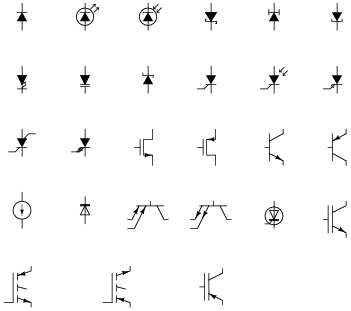
When you see an electronic device symbol such as any one of these, which direction do the symbols' intrinsic arrows represent, electron or conventional flow?
|
|
The situation is a bit more complex than simply saying that the arrow points in the direction of conventional flow (the standard answer). For a semiconductor device (diode, transistor, thyristor, etc.), an arrowhead represents a PN junction, with the fat end of the arrowhead representing the "P" side and the pointed end representing the "N" side. This much is unambiguous:

|
|
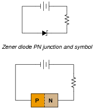
However, there is at least one device whose normal direction of current (in conventional flow) goes against this arrow: the zener diode.
|
|
This example can be quite confusing, because the diode is designed to break down in reverse-bias mode. Zener diodes can and will conduct when forward-biased, just like any other diode, but what makes them useful is their reverse-bias behavior. So although it is definitely easier for current to go the "correct" way through a zener diode (arrowhead in the direction of conventional flow), the normal operating direction of current is opposite.
Some semiconductor devices use arrowheads to denote the presence of a non-conducting PN junction. Examples of this include JFETs and MOSFETs:
|
|
Like the zener diode, the PN junctions shown by the arrowheads in these symbols are designed to operate in reverse-bias mode. Unlike the zener diode, however, the PN junctions within these devices are not supposed to break down, and therefore normally carry negligible current. Here, the arrows represent the direction that conventional flow would go, provided the necessary applied voltages to forward-bias those junctions, even though these devices do not normally operate in that mode.
Notes:
Your students can see how confusing this can be, with arrowheads sometimes representing direction of current and sometimes not. In a semiconductor device, an arrowhead simply represents a PN junction, with the direction of that arrowhead representing how conventional flow would go if that PN junction were forward-biased.
Then, of course, we have the symbol for a current source, whose arrow always points in the direction of conventional flow.
It should become apparent that conventional flow is the easiest approach when working with semiconductor devices. There are many people (technicians, especially) who successfully apply electron flow to the analysis of semiconductor devices, but they have to train themselves to think ägainst the arrow." This adds one more level of confusion to an already (potentially) confusing topic, which is why I personally choose to teach conventional flow when first exposing students to semiconductor devices.
Any way you approach this subject, it is a sad state of affairs!
Question 7:
Two people are debating electron flow versus conventional flow. One of them says that the you will get different results predicting polarity of voltage drops in a resistive circuit depending on which convention you use. The other person says the convention for labeling current does not matter at all, and that the correct polarities will be predicted either way.
Which of these two people is correct? Explain why, and give an example to prove your point.
|
|
Notes:
It is important to remember that there is only one convention for using "+" and "-" symbols to designate the polarity of a voltage drop (thankfully!).
Question 8:
Suppose a person is more familiar with conventional flow notation than electron flow notation. If this person find themselves in a situation where they must draw the direction of current according to electron flow notation, what advice would you give them for making the transition.
Notes:
A good strategy might be to use a pencil and lightly draw the arrows in the direction of conventional flow, then over-draw those arrows in the reverse direction using more hand pressure (making a darker line).
It should go without saying that this technique works just as well for the person who is more comfortable with electron flow notation, but must switch to conventional flow for some reason.
Question 9:
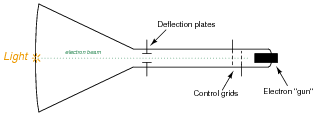
A Cathode Ray Tube, or CRT, is the heart of an analog oscilloscope. It functions by aiming a focused beam of electrons at a phosphorescent screen, causing light at the point of impact:
|
|
What style of current notation (electron or conventional) would best suit a description for the operation of a CRT?
Notes:
The answer given provides a clue as to why electron flow notation is still popular among technicians and the institutions that train them. There is a legacy of electron-flow-based instruction originating from the days when vacuum tubes were the predominant active component in electronic circuits. If you are teaching the operation of these devices in the simplest terms, so that non-engineers can understand them, it would make the most sense to standardize on a notation for current that follows the actual electrons. Electrical engineers, on the other hand, established their own convention for designating direction of current before the electron was even discovered, which is why that branch of electrical science still denotes the direction of current opposite the direction of electron motion.
Question 10:
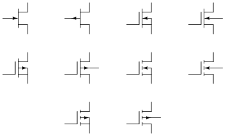
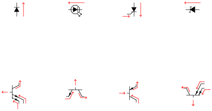
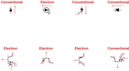
In the following graphic, you will see the directions of currents labeled with arrows for each semiconductor component. Some of these arrows are pointing in the direction of conventional flow, while others are pointing in the direction of electron flow. Determine which convention is being used to label currents for each component (note: I have only used one convention for each component - I have not mixed conventional and electron flow while labeling multiple currents on the same component!).
|
|
|
|
Notes:
The only clues as to notation are the arrows. Students may not be at the point where they can recognize the proper directions of current for the non-arrowed component terminals, but at least they should be able to compare the current arrows against the component symbol arrows and see whether there is agreement (conventional flow) or disagreement (electron flow).