Basic logic gates
Question 1:
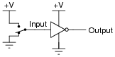
Identify the type of logic gate shown in this schematic diagram, and explain why it has the name it does:
|
|
Note: inverter gates are often shown like this instead:
|
|
Note: inverter gates are sometimes referred to as NOT gates, because when the input is high, the output will not be high.
Notes:
Your students should have no great difficulty identifying this particular logic gate if they have a good digital electronics reference book at their disposal.
Question 2:
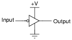
Identify the type of logic gate shown in this schematic diagram, and explain why it has the name it does:

|
|
Follow-up question: show how a light-emitting diode could be connected to the output of this logic gate to provide visual indication of its output state.
Challenge question: show how this logic gate could drive a high-current load such as a solenoid or an electric motor.
Notes:
Your students should have no great difficulty identifying this particular logic gate if they have a good digital electronics reference book at their disposal.
Question 3:
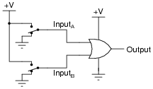
Identify the type of logic gate shown in this schematic diagram, and explain why it has the name it does:
|
|
Follow-up question: replace the two SPDT switches with SPST switches, complete with pullup or pulldown resistors as necessary.
Notes:
Your students should have no great difficulty identifying this particular logic gate if they have a good digital electronics reference book at their disposal.
Question 4:
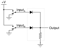
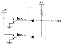
Crude logic gates circuits may be constructed out of nothing but diodes and resistors. Take for example this logic gate circuit:
|
|
Identify what type of logic function is represented by this gate circuit (AND, OR, inverter, etc.).
Notes:
Diode-resistor gate circuits such as this are rarely used in real digital circuitry because they have no capacity to amplify weak input signals. They also have no capacity for signal inversion, rendering them incapable of representing a great many logic function types. Gates made from transistors are much preferred over diode-resistor technology.
Question 5:
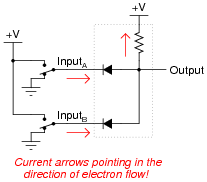
Crude logic gates circuits may be constructed out of nothing but diodes and resistors. Take for example this logic gate circuit:
|
|
Identify what type of logic function is represented by this gate circuit (AND, OR, inverter, etc.). Also, trace the directions of all currents in this circuit.
|
|
Follow-up question: show how the two SPDT switches could be replaced by SPST switches (without the need for pullup or pulldown resistors).
Challenge question: explain why it may be impractical to design this diode-resistor gate circuit to directly drive an LED so that it lights up when the output state is "high."
Notes:
Diode-resistor gate circuits such as this are rarely used in real digital circuitry because they have no capacity to amplify weak input signals. They also have no capacity for signal inversion, rendering them incapable of representing a great many logic function types. Gates made from transistors are much preferred over diode-resistor technology.
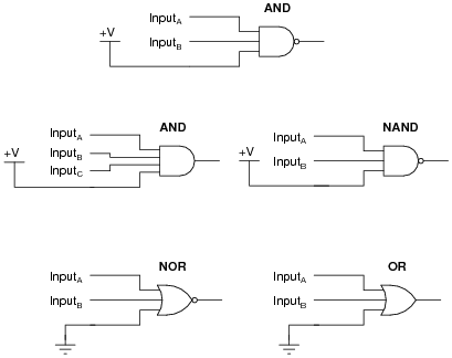
Question 6:
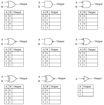
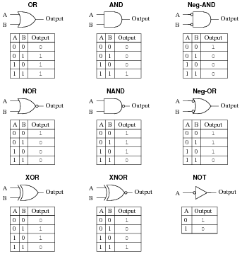
Identify each of these logic gates by name, and complete their respective truth tables:
|
|
|
|
Notes:
In order to familiarize students with the standard logic gate types, I like to given them practice with identification and truth tables each day. Students need to be able to recognize these logic gate types at a glance, or else they will have difficulty analyzing circuits that use them.
Question 7:
One way to think of the basic logic gate types (all but the XOR and XNOR gates) is to consider what single input state guarantees a certain output state. For example, we could describe the function of an OR gate as such:
|
Identify what type of gate is represented by each of the following phrases:
- �
- Any high input guarantees a low output.
- �
- Any low input guarantees a high output.
- �
- Any low input guarantees a low output.
- �
- Any high input guarantees a low output: NOR gate.
- �
- Any low input guarantees a high output: NAND gate.
- �
- Any low input guarantees a low output: AND gate.
Notes:
This is a very useful way to think of the different logic gate types, as often you are faced with a choice of which gate type to use for a specific function in a digital circuit based on a requirement cast in these terms (Äny blank input guarantees a blank output").
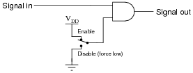
For example, we might need a gate to perform a "disable" function for a digital signal:

|
|
Considered in terms of what input state forces a low output, the choice to use an AND gate becomes obvious.
Question 8:
One way to think of logic gate types is to consider what input states guarantee a certain output state. For example, we could describe the function of an AND gate as such:
|
Identify what type of gate is represented by each of the following phrases:
- �
- Any low input guarantees a high output.
- �
- Any high input guarantees a low output.
- �
- Any high input guarantees a high output.
- �
- Any difference in the inputs guarantees a high output.
- �
- Any difference in the inputs guarantees a low output.
Also, explain how this sort of gate identification could be useful in troubleshooting logic gate circuits.
- �
- Any low input guarantees a high output: NAND gate.
- �
- Any high input guarantees a low output: NOR gate.
- �
- Any high input guarantees a high output: OR gate.
- �
- Any difference in the inputs guarantees a high output: XOR gate.
- �
- Any difference in the inputs guarantees a low output: XNOR gate.
Notes:
This is a very useful way to think of the different logic gate types, as often you are faced with a choice of which gate type to use for a specific function in a digital circuit based on a requirement cast in these terms (Äny blank input guarantees a blank output").
For example, we might need a gate to perform a "disable" function for a digital signal:
|
|
Considered in terms of what input state forces a low output, the choice to use an AND gate becomes obvious.
Question 9:
A different way to view the functions of two-input logic gates is to think of them in terms of signal controllers, where the status of one input affects how the other input's signal passes through to the output. The generic schematic diagram for this format is as such:
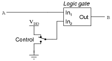
|
|
Identify the types of logic gates which do the following (there is more than one type of gate for each of the following rules!):
- �
- B = A when Control is high
- �
- B = A when Control is low
- �
- B = [`A] when Control is high
- �
- B = [`A] when Control is low
Also, explain how an understanding of this can be helpful in troubleshooting faulted logic gates.
- �
- B = A when Control is high: AND gate and XNOR gate.
- �
- B = A when Control is low: OR gate and XOR gate.
- �
- B = [`A] when Control is high: NAND gate and XOR gate.
- �
- B = [`A] when Control is low: NOR gate and XNOR gate.
Follow-up question: explain why XOR and XNOR gates are so useful as signal controllers.
Notes:
This is a very useful way to think of the different logic gate types, as it is often required to use a gate as a controlled buffer or controlled inverter.
Question 10:
Many types of logic gate circuits are built with more than two inputs. These are useful, even necessary, in some digital circuit applications. Research the part numbers and datasheets of the following logic gate integrated circuits:
- �
- Triple 3-input NOR gate
- �
- Dual 4-input AND gate
- �
- Single 8-input NAND gate
Notes:
If you haven't already, ask your students to provide a sample truth table for any of these gates.
Question 11:
Complete the truth table for a three-input AND gate:

|
|
-
A B C Output
0 0 0
0 0 1
0 1 0
0 1 1
1 0 0
1 0 1
1 1 0
1 1 1
-
A B C Output
0 0 0 0
0 0 1 0
0 1 0 0
0 1 1 0
1 0 0 0
1 0 1 0
1 1 0 0
1 1 1 1
Follow-up question: how do you suppose the truth tables would look like for three-input OR, NOR, and NAND gates? Explain how one may transition from the regular two-input gates to gate circuits with more than two inputs. What remains the same despite additional input lines?
Notes:
There isn't much to comment on here, but this is a concept some students do not immediately see (how gates work with more than two inputs).
Question 12:
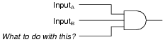
Suppose you needed a two-input AND gate, but happened to have an unused 3-input AND gate in one of the integrated circuits ("chips") already in the system you were building. Of course, you could just add another IC containing 2-input AND gates, but it seems a shame to waste the 3-input gate already there.
Explain what you would need to do with the third input terminal on this gate in order to use it as a 2-input AND gate:
|
|
Now, explain what to do with each of the following gates' third inputs, in order to use each of them as 2-input gates:
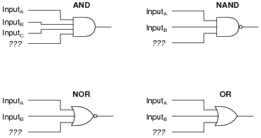
|
|
In each case, describe why your solution works.
|
|
Notes:
A helpful way for students to think about this question is to consider gates in terms of what input state forces the output to go to a particular state. For example, AND gate outputs are forced low by any low input, therefore the unused input had better not be tied to ground - the only remaining option is to tie it high.