Safety grounding
Question 1:
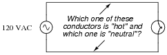
In simple AC power systems, one of the two conductors is typically called the hot, while the other conductor is typically called the neutral. What distinguishes the "hot" conductor from the "neutral" conductor in such a system? In other words, what exactly determines whether a conductor will be called either "hot" or "neutral"?
|
|
|
|
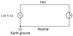
Follow-up question #1: in a power circuit such as this, there is typically a single fuse or circuit breaker for overcurrent protection. Identify the best location to place this fuse or circuit breaker in the circuit.
Follow-up question #2: explain how to use a multimeter to identify the "hot" and "neutral" conductors of a power system such as this.
Notes:
Ask your students what safety issues surround the "hot" and "neutral" conductors, respectively. What do the names imply about relative hazard, and why is this? Ask them to explain how these safety considerations impact the placement of the overcurrent protection device.
Question 2:
Explain why most electrical power systems have one of their current-carrying conductors connected to earth ground ("grounded"). Why not just leave all power conductors ungrounded? Would this not reduce electric shock hazard?
Notes:
Be sure to discuss with your students the benefits and drawbacks of power system grounding. There are some instances where systems are left intentionally ungrounded because the safety benefit of grounding them is negligible (high-voltage power distribution systems may often be ungrounded for this reason). In low-voltage (120 volt) domestic power systems, though, grounding is required by law.
Question 3:
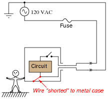
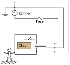
Is there any shock hazard posed to a person touching the metal case of this appliance? Explain your answer.
|
|
Follow-up question: what do the double-chevron symbols represent in a schematic diagram?

|
|
Notes:
Even though no shock hazard presently exists in the circuit, ask your students to identify a condition where the ßhorted" wire inside the appliance would pose a shock hazard. What would have to change in order for this wiring fault to pose a hazard?
Question 4:
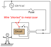
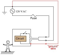
Is there any shock hazard posed to a person touching the metal case of this appliance? Explain your answer.
|
|
Notes:
Aside from removing the ßhort" connecting the power conductor to the metal case of the appliance, what else could be done to eliminate the shock hazard in this scenario? Discuss this with your students.
Question 5:
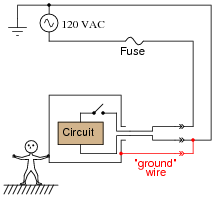
The metal case of this appliance is grounded by means of a third conductor:
|
|
Explain how this grounding connection makes the appliance safer for anyone touching its metal case.
Notes:
Ask your students to explain why the case's electrical commonality with earth makes it safer to touch. What do they know about ëlectrically common points" in a circuit, and voltage between those points?
Question 6:
What is a polarized power plug, and what does this have to do with electrical safety?
Notes:
Discuss with your students the relative merits of polarized plugs versus three-wire plugs that provide a hard ground connection with the frame of the electrical device. Which plug type provides a greater level of safety? Why?
Question 7:
The presence of a "ground" wire increases the degree of electrical safety for anyone using an electrical appliance. It entails having a third "prong" on the power plug, connecting with a third hole on the power receptacle, which connects to a separate wire running all the way back to the power system's grounding point:
|
|
But why not eliminate all that extra wiring, and simply connect the third hole on the power receptacle to the "neutral" wire?
|
|
Why would this idea be unwise?
Notes:
Discuss this particular failure scenario with your students, drawing a schematic diagram if necessary. Not only does this illustrate the importance of having a separate ground conductor, but it also shows how the neutral wire can potentially be unsafe to touch!
Question 8:
In the United States of America, the National Electrical Code (NEC) specifies certain color codes to be used for designation of grounded, grounding, and ungrounded wires in AC power systems. First, relate the terms "hot," "neutral," and "ground" to the terms "grounded," "grounding," and üngrounded". Then, describe the acceptable color codes for each conductor. Also, note the article and section of the National Electrical Code under which these specifications are found.
Grounding = Bare (uninsulated), green, or green with a yellow stripe.
Ungrounded = Colors other than white, natural grey, or green.
Notes:
It is important to note that even though these color codes have been standardized for many years, it is unwise to rely on color coding as an indication of hazard. In other words, just because a wire has green insulation does not mean it is necessarily safe to touch! There will always be mistakes made from time to time in wire installation, and in older systems where someone might have re-connected wires in incorrect ways. When in doubt, always use a voltmeter to check for the presence of hazardous voltage!
Question 9:
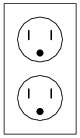
Explain how you would use a voltmeter to identify the "hot," "neutral," and "ground" conductors on a three-prong power receptacle:
|
|
Notes:
Knowing how to check for proper wiring in power receptacles is a very practical skill for homeowners. Sure, there are simple neon-lamp testers available that you can simply plug in to a receptacle to test it, but using a voltmeter requires knowledge.
Incidentally, this test is very easy to perform during class discussion time, as multiple power receptacles should be available in any classroom. Be sure to review certain basic safety rules (use one hand only, etc.) when performing this test!
Question 10:
Special safety devices called Ground Fault Current Interrupters, or GFCI's, reduce the risk of shock hazard in electrical systems even where there is no ground conductor. Explain the operating principle of a GFCI. How are they able to sense a "ground fault" condition, so as to automatically turn off power to a receptacle?
Notes:
Be sure to discuss with your students what "differential current measurement" means, rather than assume they all researched the answer in greater detail than what is provided here. This really is a clever way to detect the presence of a ground fault!
You should point out to your students that GFCI power receptacles are commonly installed in "wet" areas of residences, such as in the bathroom and outside, where the hazard of ground-fault electric shock is maximized by the presence of water.
This question also provides an opportunity to discuss why the presence of water at a point of bodily contact increases the severity of electric shock.
Question 11:
Suppose a GFCI is rated to "trip" with a ground fault current of 5 mA. Given a source voltage of 115 volts, calculate the ground fault resistance range required to trip.
Notes:
This question requires the use of Ohm's Law, but to calculate a range of resistance values and not just a singular value. All students should be able to obtain the figure of 23 kW, but some may be confused as to whether this is a minimum or a maximum resistance value needed to trip the GFCI. Discuss this with your students, asking them to explain how we know 23 kW is a maximum figure and not a minimum figure.
Question 12:
I once watched a television advertisement for an electric drill, in which one of the people selling this product claimed it was "double-insulated," to which the other person replied, "So it doesn't get hot in your hand, right?"
What do you think of this comment? Is this what "double-insulated" means?
Notes:
One fact of interest here is that double-insulated tools usually do not have three-prong power plugs. In other words, they do not need a "ground" wire to ensure operator safety.