Kirchhoff's Laws
Question 1:
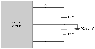
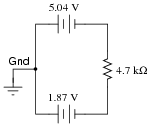
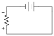
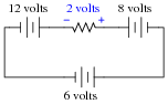
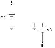
Many electronic circuits use what is called a split or a dual power supply:
|
|
Determine what a digital voltmeter would indicate if connected between the following points:
- �
- Red lead on Ä", black lead on ground
- �
- Red lead on "B", black lead on ground
- �
- Red lead on Ä", black lead on "B"
- �
- Red lead on "B", black lead on Ä"
NOTE: in electronic systems, "ground" is often not associated with an actual earth-soil contact. It usually only refers to a common point of reference somewhere in the circuit used to take voltage measurements. This allows us to specify voltages at single points in the circuit, with the implication that "ground" is the other point for the voltmeter to connect to.
- �
- Red lead on Ä", black lead on ground (Digital voltmeter reads +15 volts)
- �
- Red lead on "B", black lead on ground (Digital voltmeter reads -15 volts)
- �
- Red lead on Ä", black lead on "B" (Digital voltmeter reads +30 volts)
- �
- Red lead on "B", black lead on Ä" (Digital voltmeter reads -30 volts)
Notes:
This question may be easily answered with only a voltmeter, two batteries, and a single "jumper" wire to connect the two batteries in series. It does not matter if the batteries are 15 volts each! The fundamental principle may still be investigated with batteries of any voltage, so this is a very easy demonstration to set up during discussion time.
Question 2:
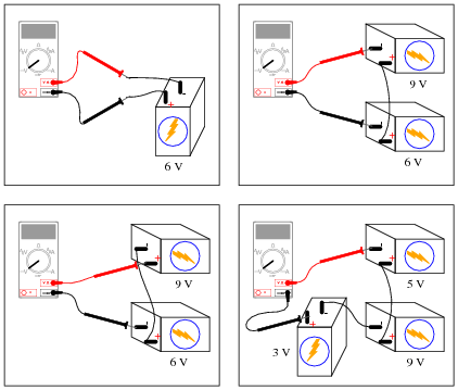
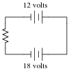
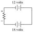
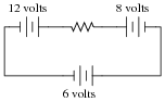
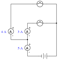
Determine what the magnitude and polarity of the voltmeter's indication will be in each case:
|
|

|
|
Notes:
Here, students must apply Kirchhoff's Voltage Law to determine what the voltmeter's indication will be. This question works well as a prelude to determining comparator (open-loop opamp) output polarities.
Question 3:
| Don't just sit there! Build something!! |
Learning to mathematically analyze circuits requires much study and practice. Typically, students practice by working through lots of sample problems and checking their answers against those provided by the textbook or the instructor. While this is good, there is a much better way.
You will learn much more by actually building and analyzing real circuits, letting your test equipment provide the änswers" instead of a book or another person. For successful circuit-building exercises, follow these steps:
- 1.
- Carefully measure and record all component values prior to circuit construction.
- 2.
- Draw the schematic diagram for the circuit to be analyzed.
- 3.
- Carefully build this circuit on a breadboard or other convenient medium.
- 4.
- Check the accuracy of the circuit's construction, following each wire to each connection point, and verifying these elements one-by-one on the diagram.
- 5.
- Mathematically analyze the circuit, solving for all values of voltage, current, etc.
- 6.
- Carefully measure those quantities, to verify the accuracy of your analysis.
- 7.
- If there are any substantial errors (greater than a few percent), carefully check your circuit's construction against the diagram, then carefully re-calculate the values and re-measure.
Avoid very high and very low resistor values, to avoid measurement errors caused by meter "loading". I recommend resistors between 1 kW and 100 kW, unless, of course, the purpose of the circuit is to illustrate the effects of meter loading!
One way you can save time and reduce the possibility of error is to begin with a very simple circuit and incrementally add components to increase its complexity after each analysis, rather than building a whole new circuit for each practice problem. Another time-saving technique is to re-use the same components in a variety of different circuit configurations. This way, you won't have to measure any component's value more than once.
Notes:
It has been my experience that students require much practice with circuit analysis to become proficient. To this end, instructors usually provide their students with lots of practice problems to work through, and provide answers for students to check their work against. While this approach makes students proficient in circuit theory, it fails to fully educate them.
Students don't just need mathematical practice. They also need real, hands-on practice building circuits and using test equipment. So, I suggest the following alternative approach: students should build their own "practice problems" with real components, and try to mathematically predict the various voltage and current values. This way, the mathematical theory "comes alive," and students gain practical proficiency they wouldn't gain merely by solving equations.
Another reason for following this method of practice is to teach students scientific method: the process of testing a hypothesis (in this case, mathematical predictions) by performing a real experiment. Students will also develop real troubleshooting skills as they occasionally make circuit construction errors.
Spend a few moments of time with your class to review some of the "rules" for building circuits before they begin. Discuss these issues with your students in the same Socratic manner you would normally discuss the worksheet questions, rather than simply telling them what they should and should not do. I never cease to be amazed at how poorly students grasp instructions when presented in a typical lecture (instructor monologue) format!
A note to those instructors who may complain about the "wasted" time required to have students build real circuits instead of just mathematically analyzing theoretical circuits:
What is the purpose of students taking your course?
If your students will be working with real circuits, then they should learn on real circuits whenever possible. If your goal is to educate theoretical physicists, then stick with abstract analysis, by all means! But most of us plan for our students to do something in the real world with the education we give them. The "wasted" time spent building real circuits will pay huge dividends when it comes time for them to apply their knowledge to practical problems.
Furthermore, having students build their own practice problems teaches them how to perform primary research, thus empowering them to continue their electrical/electronics education autonomously.
In most sciences, realistic experiments are much more difficult and expensive to set up than electrical circuits. Nuclear physics, biology, geology, and chemistry professors would just love to be able to have their students apply advanced mathematics to real experiments posing no safety hazard and costing less than a textbook. They can't, but you can. Exploit the convenience inherent to your science, and get those students of yours practicing their math on lots of real circuits!
Question 4:
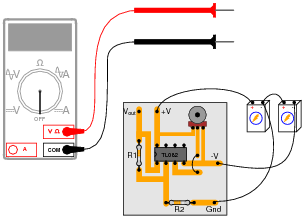
Suppose a technician is checking the operation of the following electronic circuit:
|
|
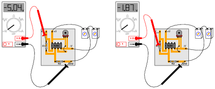
She decides to measure the voltage on either side of resistor R1 with reference to ground, and obtains these readings:
|
|
On the top side of R1, the voltage with reference to ground is -5.04 volts. On the bottom side of R1, the voltage with reference to ground is -1.87 volts. The color code of resistor R1 is Yellow, Violet, Orange, Gold. From this information, determine the following:
- �
- Voltage across R1 (between top to bottom):
- �
- Polarity (+ and -) of voltage across R1:
- �
- Current (magnitude) through R1:
- �
- Direction of current through R1:
Additionally, explain how this technician would make each one of these determinations. What rules or laws of electric circuits would she apply?
- �
- Voltage across R1 (between top to bottom): 3.17 volts
- �
- Polarity (+ and -) of voltage across R1: (-) on top, (+) on bottom
- �
- Current (magnitude) through R1: 67.45 mA
- �
- Direction of current through R1: upward, following conventional flow
Follow-up question: calculate the range of possible currents, given the specified tolerance of resistor R1 (67.45 mA assumes 0% error).
Challenge question: if you recognize the type of circuit this is (by the part number of the IC "chip": TL082), identify the voltage between pin 3 and ground.
Notes:
This is a good example of how Kirchhoff's Voltage Law is more than just an abstract tool for mathematical analysis - it is also a powerful technique for practical circuit diagnosis. Students must apply KVL to determine the voltage drop across R1, and then use Ohm's Law to calculate its current.
If students experience difficulty visualizing how KVL plays a part in the solution of this problem, show them this illustration:
|
|
By the way, the answer to the challenge question may only be realized if students recognize this circuit as a noninverting opamp voltage amplifier. The voltage at pin 3 (noninverting input) will be the same as the voltage at pin 2 (inverting input): -1.87 volts.
Question 5:
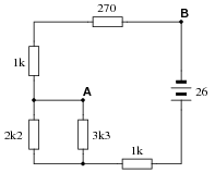
Calculate the amount of voltage between points A and B in this circuit. Be sure to identify polarity as well as magnitude:
|
|
Notes:
Nothing here but series-parallel calculation practice, combined with KVL. Ask your students to explain how they calculated this voltage, because there is definitely more than one way to do it!
Question 6:
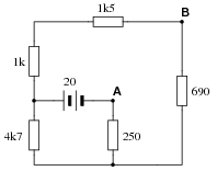
Calculate the amount of voltage between points A and B in this circuit. Be sure to identify polarity as well as magnitude:
|
|
Notes:
Nothing here but series-parallel calculation practice, combined with KVL. Ask your students to explain how they calculated this voltage, because there is definitely more than one way to do it!
Question 7:
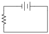
Determine the polarity of voltage across the resistor in this simple circuit, and be prepared to explain how you did so:
|
|
|
|
Notes:
The answer to this question is fairly trivial, but the real point of it is to get students thinking about how and why it is the way it is. One thing I've noticed as an instructor of electronics is that most students tend to follow the rule of proximity: the resistor's voltage drop polarity is determined by proximity to poles of the battery. The resistor terminal closest to the battery's negative terminal must be negative as well, or so the thinking goes. While this is sound reasoning in a simple circuit such as this, it can lead to confusion in circuits where there is more than one power source at work!
Question 8:
Determine the polarity of voltage across the resistor in this simple circuit, and be prepared to explain how you did so:
|
|
|
|
Follow-up question: are the battery voltage values important to the answer? Explain why or why not.
Notes:
The answer to this question is fairly simple, but the real point of it is to get students thinking about how and why it is the way it is. One thing I've noticed as an instructor of electronics is that most students tend to follow the rule of proximity: the resistor's voltage drop polarity is determined by proximity to poles of the battery. The resistor terminal closest to the battery's negative terminal must be negative as well, or so the thinking goes.
In this particular circuit, though, the rule of proximity does not hold very well, and a different rule is necessary.
Question 9:
Determine both the polarity of voltage across the resistor in this circuit, and how much voltage will be dropped across the resistor:
|
|
Explain the procedure(s) you used to answer both these questions.
|
|
Notes:
The answer to this question is fairly simple, but the real point of it is to get students thinking about how and why it is the way it is. One thing I've noticed as an instructor of electronics is that most students tend to follow the rule of proximity: the resistor's voltage drop polarity is determined by proximity to poles of the battery. The resistor terminal closest to the battery's negative terminal must be negative as well, or so the thinking goes.
In this particular circuit, though, the rule of proximity does not hold very well, and a different rule is necessary.
Question 10:
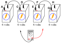
Determine what a digital voltmeter (DVM) would indicate if connected between the following points in this circuit:
|
|
- �
- Red lead on A, black lead on H
- �
- Red lead on C, black lead on G
- �
- Red lead on F, black lead on B
- �
- Red lead on F, black lead on A

|
|
- �
- Red lead on A, black lead on H = +24 volts
- �
- Red lead on C, black lead on G = +12 volts
- �
- Red lead on F, black lead on B = -12 volts
- �
- Red lead on F, black lead on A = -18 volts
Notes:
Kirchhoff's Voltage Law (KVL) is very easily explored in real life with a set of batteries and "jumper wire" connections. Encourage your students to build battery circuits like the one shown in this question, to be able to see the results for themselves!
One really nice feature of digital multimeters (DMMs) is the ability to register negative as well as positive quantities. This feature is very useful when teaching Kirchhoff's Laws, with the algebraic (sign-dependent) summation of voltages and currents.
Question 11:
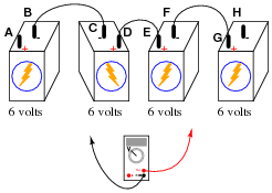
Determine what a digital voltmeter (DVM) would indicate if connected between the following points in this circuit:
|
|
- �
- Red lead on A, black lead on H
- �
- Red lead on C, black lead on G
- �
- Red lead on F, black lead on B
- �
- Red lead on F, black lead on A
|
|
- �
- Red lead on A, black lead on H = +12 volts
- �
- Red lead on C, black lead on G = 0 volts
- �
- Red lead on F, black lead on B = 0 volts
- �
- Red lead on F, black lead on A = -6 volts
Notes:
Kirchhoff's Voltage Law (KVL) is very easily explored in real life with a set of batteries and "jumper wire" connections. Encourage your students to build battery circuits like the one shown in this question, to be able to see the results for themselves!
One really nice feature of digital multimeters (DMMs) is the ability to register negative as well as positive quantities. This feature is very useful when teaching Kirchhoff's Laws, with the algebraic (sign-dependent) summation of voltages and currents.
Students may arrive at more than one method for determining voltmeter indications in problems like these. Encourage this type of creativity during discussion time, as it both helps students gain confidence in being able to approach problems on their own terms, as well as educates those students who might be confused with the concept. Quite often the explanation of a peer is more valuable than the explanation of an instructor. When students are given the freedom to explore problem-solving methods, and then share those methods with their classmates, substantial learning always results.
Question 12:
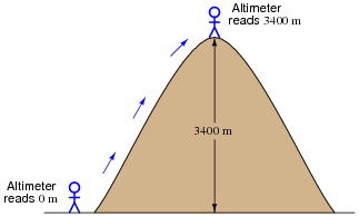
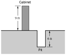
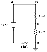
A barometric altimeter is a device used to measure altitude (height) by means of atmospheric pressure. The higher you go up from sea level, the less air pressure you encounter. This decrease in air pressure is closely correlated with height, and thus can be used to infer altitude.
This type of altimeter usually comes equipped with a "zero" adjustment, so that the instrument's indication may be offset to compensate for changes in air pressure resulting from different weather conditions. This same "zero" adjustment may also be used to establish the altimeter's zero indication at any arbitrary height.
For example, if a mountain climber sets her barometric altimeter to zero meters at the base of a mountain, then climbs to the summit of that mountain (3400 meters higher than the base), the altimeter should register 3400 meters at the summit:
|
|
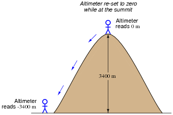
While at the summit, the climber may re-set the altimeter's "zero" adjustment to register 0 meters once again. If the climber then descends to the base of the mountain, the altimeter will register -3400 meters:
|
|
Explain how this scenario of mountain climbing and altimeter calibration relates to the measurement of voltage between points A and B in the following circuit:
|
|
Notes:
Physical height (and depth) is a very useful analogy for electrical potential, helping students relate this abstract thing called "voltage" to more common differential measurements.
Question 13:
Determine the amount of voltage measured at points A and B with reference to ground, and also determine voltage VAB (defined here as the voltage indicated by a voltmeter with the red test lead touching point A and the black test lead touching point B):
|
|
VB = +6 volts
VAB = +3 volts
Follow-up question: explain why the mathematical signs ("+") are important in these answers.
Notes:
Determining differential voltages is a skill that many students find frustrating to attain. There is more than one way to explain how to arrive at +3 volts as the answer for VAB, and it is good for students to see more than one way presented.
Question 14:
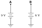
A student is puzzled by a problem given by her instructor. The task is to determine the voltage VAB (defined by the instructor as the voltage indicated by a voltmeter with the red test lead touching point A and the black test lead touching point B) in this circuit:
|
|
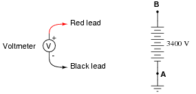
The student has already figured out that VA = +9 V and VB = -6 V, but does not know for certain how to calculate the voltage between points A and B. Asking her instructor for an explanation, the instructor begins to draw this illustration:
|
|
Before the instructor begins to explain what the illustration means, however, he receives a call on his telephone and must leave the student momentarily. The student then asks you to help explain what the instructor's illustration might mean, and how it applies to the problem of determining voltage VAB in the original circuit.
What would your explanation be? Where do you think the instructor was going with this illustration, and how it might relate to voltages in a circuit?
Notes:
It may be good to remind your students that voltage is and forever will be a quantity between two points and never defined at a single point. The only reason we can say VA = +9 volts and VB = -6 volts is because there is a ground point in the circuit, which by convention is the point of reference for any voltages defined at other, single points in the circuit.
Question 15:
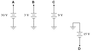
Determine the voltages registered by a voltmeter between the following points in this circuit:
|
|
VA = (red lead on A, black lead on ground)
VB = (red lead on B, black lead on ground)
VC = (red lead on C, black lead on ground)
VD = (red lead on D, black lead on ground)
VAC = (red lead on A, black lead on C)
VDB = (red lead on D, black lead on B)
VBA = (red lead on B, black lead on A)
VBC = (red lead on B, black lead on C)
VCD = (red lead on C, black lead on D)
VB = +3 volts (red lead on B, black lead on ground)
VC = +9 volts (red lead on C, black lead on ground)
VD = -15 volts (red lead on D, black lead on ground)
VAC = +21 volts (red lead on A, black lead on C)
VDB = -18 volts (red lead on D, black lead on B)
VBA = -27 volts (red lead on B, black lead on A)
VBC = -6 volts (red lead on B, black lead on C)
VCD = +24 volts (red lead on C, black lead on D)
Notes:
Discuss with your students multiple techniques of solving for these voltages, asking them first for their solution strategies.
Question 16:
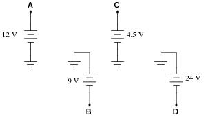
Determine the voltages registered by a voltmeter between the following points in this circuit:
|
|
VA = (red lead on A, black lead on ground)
VB = (red lead on B, black lead on ground)
VC = (red lead on C, black lead on ground)
VD = (red lead on D, black lead on ground)
VAC = (red lead on A, black lead on C)
VDB = (red lead on D, black lead on B)
VBA = (red lead on B, black lead on A)
VBC = (red lead on B, black lead on C)
VCD = (red lead on C, black lead on D)
VB = -9 volts (red lead on B, black lead on ground)
VC = +4.5 volts (red lead on C, black lead on ground)
VD = -24 volts (red lead on D, black lead on ground)
VAC = +7.5 volts (red lead on A, black lead on C)
VDB = -15 volts (red lead on D, black lead on B)
VBA = -21 volts (red lead on B, black lead on A)
VBC = -13.5 volts (red lead on B, black lead on C)
VCD = +28.5 volts (red lead on C, black lead on D)
Notes:
Discuss with your students multiple techniques of solving for these voltages, asking them first for their solution strategies.
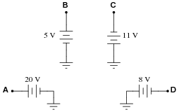
Question 17:
Determine the voltages registered by a voltmeter between the following points in this circuit:
|
|
VA = (red lead on A, black lead on ground)
VB = (red lead on B, black lead on ground)
VC = (red lead on C, black lead on ground)
VD = (red lead on D, black lead on ground)
VAC = (red lead on A, black lead on C)
VDB = (red lead on D, black lead on B)
VBA = (red lead on B, black lead on A)
VBC = (red lead on B, black lead on C)
VCD = (red lead on C, black lead on D)
VB = +5 volts (red lead on B, black lead on ground)
VC = -11 volts (red lead on C, black lead on ground)
VD = -8 volts (red lead on D, black lead on ground)
VAC = +31 volts (red lead on A, black lead on C)
VDB = -13 volts (red lead on D, black lead on B)
VBA = -15 volts (red lead on B, black lead on A)
VBC = +16 volts (red lead on B, black lead on C)
VCD = -3 volts (red lead on C, black lead on D)
Notes:
Discuss with your students multiple techniques of solving for these voltages, asking them first for their solution strategies.
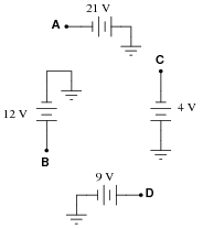
Question 18:
Determine the voltages registered by a voltmeter between the following points in this circuit:
|
|
VA = (red lead on A, black lead on ground)
VB = (red lead on B, black lead on ground)
VC = (red lead on C, black lead on ground)
VD = (red lead on D, black lead on ground)
VAC = (red lead on A, black lead on C)
VDB = (red lead on D, black lead on B)
VBA = (red lead on B, black lead on A)
VBC = (red lead on B, black lead on C)
VCD = (red lead on C, black lead on D)
VB = +12 volts (red lead on B, black lead on ground)
VC = -4 volts (red lead on C, black lead on ground)
VD = +9 volts (red lead on D, black lead on ground)
VAC = -17 volts (red lead on A, black lead on C)
VDB = -3 volts (red lead on D, black lead on B)
VBA = +33 volts (red lead on B, black lead on A)
VBC = +16 volts (red lead on B, black lead on C)
VCD = -13 volts (red lead on C, black lead on D)
Notes:
Discuss with your students multiple techniques of solving for these voltages, asking them first for their solution strategies.
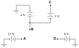
Question 19:
Determine the voltages registered by a voltmeter between the following points in this circuit:
|
|
VA = (red lead on A, black lead on ground)
VB = (red lead on B, black lead on ground)
VC = (red lead on C, black lead on ground)
VD = (red lead on D, black lead on ground)
VAC = (red lead on A, black lead on C)
VDB = (red lead on D, black lead on B)
VBA = (red lead on B, black lead on A)
VBC = (red lead on B, black lead on C)
VCD = (red lead on C, black lead on D)
VB = +4 volts (red lead on B, black lead on ground)
VC = +7 volts (red lead on C, black lead on ground)
VD = -6 volts (red lead on D, black lead on ground)
VAC = +6 volts (red lead on A, black lead on C)
VDB = -10 volts (red lead on D, black lead on B)
VBA = -9 volts (red lead on B, black lead on A)
VBC = -3 volts (red lead on B, black lead on C)
VCD = +13 volt (red lead on C, black lead on D)
Notes:
Discuss with your students multiple techniques of solving for these voltages, asking them first for their solution strategies.
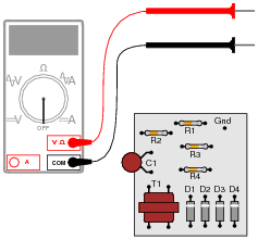
Question 20:
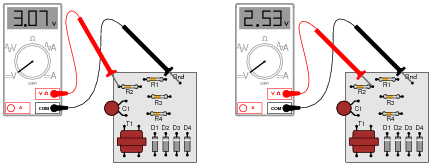
Suppose you wanted to measure the amount of current going through resistor R2 on this printed circuit board, but did not have the luxury of breaking the circuit to do so (unsoldering one end of the resistor, detaching it from the PCB, and connecting an ammeter in series). All you can do while the circuit is powered is measure voltage with a voltmeter:
|
|
So, you decide to touch the black probe of the voltmeter to the circuit's "Gnd" (ground) test point, and measure the voltage with reference to ground on both sides of R2. The results are shown here:
|
|
R2's color code is Orange, Orange, Red, Gold. Based on this information, determine both the direction and the magnitude of DC current through resistor R2, and explain how you did so.
Follow-up question: this technique for estimating resistor current depends on one important assumption. Describe what this assumption is, and how the accuracy of your current calculation may be affected if the assumption is invalid.
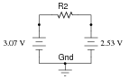
Notes:
This is a good example of how Kirchhoff's Voltage Law is more than just an abstract tool for mathematical analysis - it is also a powerful technique for practical circuit diagnosis. Students must apply KVL to determine the voltage drop across R2, and then use Ohm's Law to calculate its current.
If students experience difficulty visualizing how KVL plays a part in the solution of this problem, show them this illustration:
|
|
Question 21:
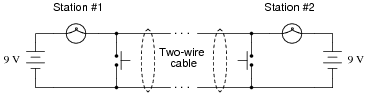
Shown here is a simple telegraph circuit:
|
|
Explain why the lamps energize when either pushbutton is actuated, and why they de-energize when both pushbuttons are open (despite there being an unbroken circuit connecting both lamps and both batteries).
Notes:
This is a simple circuit, yet practical in its function as a telegraph and as an example of KVL in action.
Question 22:
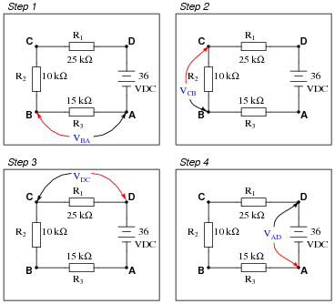
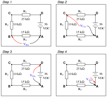
Imagine you are using a digital voltmeter to measure voltages between pairs of points in a circuit, following the sequence of steps shown in these diagrams:
|
|
How much voltage would be registered by the voltmeter in each of the steps? Be sure to include the sign of the DC voltage measured (note the coloring of the voltmeter leads, with the red lead always on the first point denoted in the subscript: VBA = red lead on "B" and black lead on Ä"):
- �
- VBA =
- �
- VCB =
- �
- VDC =
- �
- VAD =
What is the algebraic sum of these voltages?
- �
- VBA = +10.8 volts
- �
- VCB = +7.2 volts
- �
- VDC = +18 volts
- �
- VAD = -36 volts
Notes:
Ask your students this question: "Will the algebraic sum of voltage measurements ever be other than zero in a loop?" Ask them to explain why this is, as best they can.
Question 23:
Imagine you are using a digital voltmeter to measure voltages between pairs of points in a circuit, following the sequence of steps shown in these diagrams:
|
|
How much voltage would be registered by the voltmeter in each of the steps? Be sure to include the sign of the DC voltage measured (note the coloring of the voltmeter leads, with the red lead always on the first point denoted in the subscript: VBA = red lead on "B" and black lead on Ä"):
- �
- VBA =
- �
- VCA =
- �
- VDA =
- �
- VAA =
Challenge question: how do these voltage measurements prove Kirchhoff's Voltage Law, where the algebraic sum of all voltages in a loop equals 0 volts?
- �
- VBA = +10.8 volts
- �
- VCA = +18.0 volts
- �
- VDA = +36.0 volts
- �
- VAA = 0 volts
With each successive step, one more voltage is being added to the previously measured voltage(s), as the meter measures across a larger series chain of resistors. Ultimately,
|
Notes:
Building on the knowledge of series voltages being additive, this example serves as a simple proof of Kirchhoff's Voltage Law. At the final step of the sequence, the voltage indicated by the meter must be zero volts because the two test leads are now electrically common to each other.
Question 24:
Identify each of the specified voltages in the following circuit. The subscripts refer to the specific test points (where the red test lead of the voltmeter touches the circuit), while ground is the point where the voltmeter's black lead is assumed to be attached:
|
|
For example, VB means the voltage indicated by a voltmeter with the red test lead touching point B and the black test lead touching ground.
- �
- VA =
- �
- VB =
- �
- VC =
- �
- VD =
- �
- VE =
- �
- VA = +16 volts
- �
- VB = +16 volts
- �
- VC = +10 volts
- �
- VD = 0 volts
- �
- VE = -2 volts
Follow-up question: explain how it is possible to determine that VA and VB will be exactly the same value, prior to performing any mathematical calculations.
Notes:
This question helps to familiarize students with the concept of "ground" as the default reference point for taking voltage measurements, as well as being an application of Kirchhoff's Voltage Law.
Question 25:
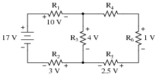
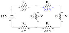
Use Kirchhoff's Voltage Law to calculate the magnitude and polarity of the voltage across resistor R4 in this resistor network:
|
|
|
|
Notes:
In your discussion, be sure to explore more than one "loop" when using KVL. Not only does this demonstrate the arbitrary nature of your loop choice, but it also serves as a double-check for your work!
It is not necessary to know anything about series-parallel or even parallel circuits in order to solve the R4's voltage - all one needs to know is how to use Kirchhoff's Voltage Law.
Question 26:
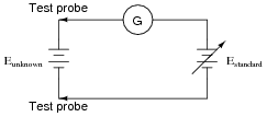
A very old but highly accurate technique for measuring voltage is to use a sensitive meter (a galvanometer) as a "balance" indicator between two voltage sources: the unknown source and a calibrated, adjustable source called the standard:
|
|
The technique is to adjust the standard voltage source until the galvanometer registers exactly zero. When this condition is met, the system is said to be "balanced," indicating that the two voltage sources are equal in magnitude to each other. This voltage magnitude is then read from the calibrated adjustment dial on the standard source.
Explain how this voltage measurement technique exploits Kirchhoff's Voltage Law, which states that the algebraic sum of all voltages in a loop must equal zero:
|
Notes:
Potentiometric voltage measurement is not only practical, but for quite a while in the early field of electrical measurements it was the only way to accurately measure voltage from "weak" (high-impedance) sources. It is still used today in electrical metrology, and serves as a simple application of KVL for students to examine.
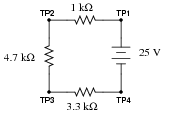
Question 27:
Calculate the amount of voltage between test points TP1 and TP3, and also the amount of voltage between test points TP2 and TP4:
|
|
VTP1-TP3 = VTP2-TP4 =
Notes:
Ask your students to explain how they obtained their answers. There is more than one correct way to answer this question!
Question 28:
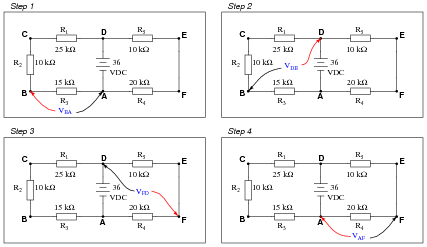
Imagine you are using a digital voltmeter to measure voltages between pairs of points in a circuit, following the sequence of steps shown in the following diagrams:
|
|
How much voltage would be registered by the voltmeter in each of the steps? Be sure to include the sign of the DC voltage measured (note the coloring of the voltmeter leads, with the red lead always on the first point denoted in the subscript: VBA = red lead on "B" and black lead on Ä"):
- �
- VBA =
- �
- VDB =
- �
- VFD =
- �
- VAF =
What is the algebraic sum of these voltages?
- �
- VBA = +10.8 volts
- �
- VDB = +25.2 volts
- �
- VFD = -24.0 volts
- �
- VAF = -12.0 volts
Notes:
Ask your students this question: "Will the algebraic sum of voltage measurements ever be other than zero in a loop?" Ask them to explain why this is, as best they can.
Question 29:
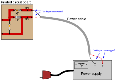
Suppose you were measuring the voltage between "test points" TP1 and TP2 on this printed circuit board, where the circuit receives DC power from a voltage source. Suddenly, this voltage decreases. Wondering if perhaps the power supply voltage itself decreased, you go back to measure its output voltage and find that it is unchanged from before:
|
|
Based on your knowledge of Kirchhoff's Voltage Law, what must have happened to cause the voltage between TP1 and TP2 on the circuit board to suddenly decrease, given the power supply's stable voltage output? Hint: the components on the circuit board are irrelevant to the answer!
Notes:
Ask your students where the increased voltage drop(s) might be located in this circuit. It might be helpful to draw the test points, power cable, and power supply as a circuit, using standard schematic symbols. Ask your students, "What type of fault might cause such voltage drop increases in this loop?"
Question 30:
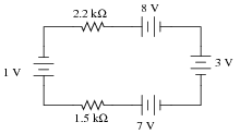
When electricity and electronics students begin learning about series circuits and Kirchhoff's Voltage Law, they are often mercilessly subjected to circuits such as this:
|
|
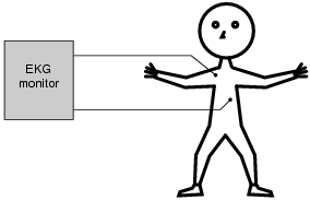
A common (and legitimate!) question asked by students is, "Where would we ever encounter a circuit such as this, with batteries opposing each other?" In practice, it is rare to find electrochemical batteries intentionally connected in such a manner, with some aiding and some opposing. However, there are many practical applications where the voltages involved are not intentional, but rather are unavoidable potentials created by junctions of dissimilar materials. Take for instance the application of EKG (electrocardiogram) measurements, where metal electrodes must be placed in contact with a human body to intercept tiny voltage signals from the contracting heart muscles:
|
|
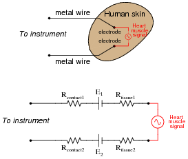
A junction of metal wire to human skin is surprisingly complex from an electrical perspective, and may be approximately modeled by the following collection of idealized components:
|
|
Resistors Rcontact1 and Rcontact2 represent electrical resistance between the metal electrodes and skin at the point of contact. Resistors Rtissue1 and Rtissue2 represent electrical resistance of human tissue between the points of electrode contact and the actual heart muscle. The two series-opposing potentials (E1 and E2) are not intentional, but rather the result of electrochemical action between the metal electrode surfaces and human skin. They cannot be eliminated, but their combined effect is minimal because they are approximately equal in magnitude. Explain how Kirchhoff's Voltage Law applies to this equivalent circuit, especially how the biomedical instrument ßees" only the heart muscle voltage signal and neither of the skin-contact potentials.
Follow-up question: why is the heart muscle represented in the equivalent circuit by an AC voltage source symbol rather than by a DC voltage source symbol (battery)? Does this matter when we apply KVL to the loop? Why or why not?
Notes:
The question of "where will we ever see this?" is too often ignored by teachers, who forget the lack of context present in their new students' understanding. Remember that this is all new to most of your students, so they lack the years of experience you have working with circuits in practical scenarios. A question like this deserves to be answered, and answered well.
Truth be known, the equivalent circuit for electrode-to-skin contact is far more complex than what is shown here (impedances everywhere!), but the point here is to simplify it enough so that students studying DC circuits and KVL would be able to grasp it.
Electrode half-cell potentials (E1 and E2 in the equivalent schematic diagram) caused by electrochemical action are not the only source of stray potentials in measurement circuits by any means! Noise voltage is a consideration in many circumstances (whether induced by outside sources or generated by physical action such as Johnson noise), thermal voltages caused by junctions of dissimilar metals, and others. If all we are doing is making crude measurements, these stray voltages will be of little concern. If precision is necessary, which is often the case in medical and scientific measurements, these spurious voltages can be devastating.
Question 31:
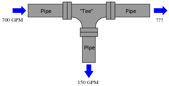
How much water must flow out of the pipe with the question-mark symbols next to it?
|
|
Explain how this hydraulic example relates to Kirchhoff's Current Law (KCL) in an electric circuit.
Notes:
Ask your students to draw an electric circuit schematic showing how the same principle illustrated in the hydraulic system would apply to electric current, with "flow rates" of 700 amps, 150 amps, and 550 amps, respectively.
Question 32:
In this circuit there is at least one ammeter that is not reading correctly:
|
|
Apply Kirchhoff's Current Law to this circuit to prove why all three current measurements shown here cannot be correct.
Notes:
Another way of stating KCL is to say, "What goes in must come out." When continuous DC currents are involved, this law is really nothing more than a restatement of the Conservation of Charge. Of course, there are transient exceptions to this law (static electric charge and discharge, for example) as well as interesting AC exceptions (current "through" a capacitor), so a hard-literal interpretation of KCL may cause confusion later one. However, it is a fairly intuitive Law to grasp, and consequently I seldom find students experiencing difficulty with it.
Question 33:
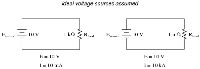
A voltage source is a source of electricity that (ideally) outputs a constant voltage. That is, a perfect voltage source will hold its output voltage constant regardless of the load imposed upon it:
|
|
In real life, there is no such thing as a perfect voltage source, but sources having extremely low internal resistance come close.
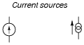
Another type of electricity source is the current source, which (ideally) outputs a constant current regardless of the load imposed upon it. A common symbol for a current source is a circle with an arrow inside (always pointing in the direction of conventional flow, not electron flow!). Another symbol is two intersecting circles, with an arrow nearby pointing in the direction of conventional flow:
|
|
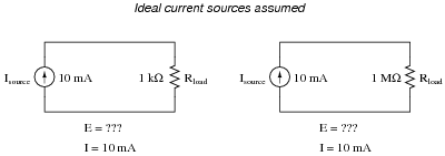
Predict how an ideal current source would behave for the following two load scenarios:
|
|
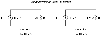
|
|
Follow-up question: identify the polarity of the voltage drops across the resistors in the circuits shown above.
Notes:
Let students know that there really is such a thing as a perfect current source, just as there is no such thing as a perfect voltage source. However, there are devices the closely approximate ideal current sources (current transformers in AC circuits and "current mirror" DC transistor circuits, for example).
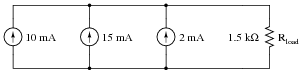
Question 34:
Calculate the total current output to the load resistor by this set of parallel-connected current sources:
|
|
Also, calculate the voltage dropped across Rload.
Follow-up question: trace the direction of current through all three sources as well as the load resistor. Compare these directions with the polarity of their shared voltage. Explain how the relationship between voltage polarity and current direction relates to each component's identity as either a source or a load.
Notes:
Have your students collectively agree on a procedure they may use to accurate discern series voltage sums and polarities. Guide their discussion, helping them identify principles that are true and valid for all series circuits.
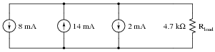
Question 35:
Calculate the total current output to the load resistor by this set of parallel-connected current sources:
|
|
Also, calculate the voltage dropped across Rload.
Follow-up question: indicate the polarity of the voltage across the load resistor with "+" and "-" symbols.
Notes:
Have your students collectively agree on a procedure they may use to accurate discern series voltage sums and polarities. Guide their discussion, helping them identify principles that are true and valid for all series circuits.
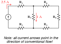
Question 36:
Use Kirchhoff's Current Law to calculate the magnitude and direction of the current through resistor R4 in this resistor network:
|
|
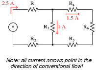
|
|
Notes:
It is not necessary to know anything about series-parallel or even parallel circuits in order to solve the R4's current - all one needs to know is how to use Kirchhoff's Current Law.
Question 37:
Use Kirchhoff's Current Law to calculate the magnitudes and directions of currents through all resistors in this circuit:
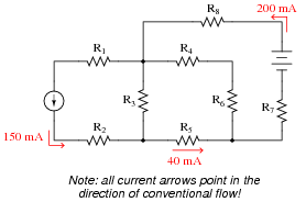
|
|
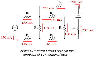
|
|
Notes:
It is not necessary to know anything about series-parallel or even parallel circuits in order to solve the R4's current - all one needs to know is how to use Kirchhoff's Current Law.
Question 38:
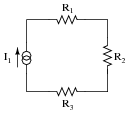
Predict how all component voltages and currents in this circuit will be affected as a result of the following faults. Consider each fault independently (i.e. one at a time, no multiple faults):
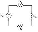
|
|
- �
- Voltage source V1 fails with increased output:
- �
- Solder bridge (short) across resistor R1:
- �
- Solder bridge (short) across resistor R2:
- �
- Resistor R3 fails open:
For each of these conditions, explain why the resulting effects will occur.
- �
- Voltage source V1 fails with increased output: All resistor currents increase, all resistor voltages increase, current through V1 increases.
- �
- Solder bridge (short) across resistor R1: All resistor currents increase, voltage across resistors R2 and R3 increase, voltage across resistor R1 decreases to zero, current through V1 increases.
- �
- Solder bridge (short) across resistor R2: All resistor currents increase, voltage across resistors R1 and R3 increase, voltage across resistor R2 decreases to zero, current through V1 increases.
- �
- Resistor R3 fails open: All resistor currents decrease to zero, voltages across R1 and R2 decrease to zero, voltage across R3 increases to equal V1.
Notes:
The purpose of this question is to approach the domain of circuit troubleshooting from a perspective of knowing what the fault is, rather than only knowing what the symptoms are. Although this is not necessarily a realistic perspective, it helps students build the foundational knowledge necessary to diagnose a faulted circuit from empirical data. Questions such as this should be followed (eventually) by other questions asking students to identify likely faults based on measurements.
Question 39:
Predict how all component voltages and currents in this circuit will be affected as a result of the following faults. Consider each fault independently (i.e. one at a time, no multiple faults):
|
|
- �
- Current source I1 fails with increased output:
- �
- Solder bridge (short) across resistor R1:
- �
- Solder bridge (short) across resistor R2:
- �
- Resistor R3 fails open:
For each of these conditions, explain why the resulting effects will occur.
- �
- Current source I1 fails with increased output: All resistor currents increase, all resistor voltages increase, voltage across I1 increases.
- �
- Solder bridge (short) across resistor R1: All resistor currents remain unchanged, voltage across resistor R1 decreases to zero, voltage across I1 decreases by the amount R1 previously dropped.
- �
- Solder bridge (short) across resistor R2: All resistor currents remain unchanged, voltage across resistor R2 decreases to zero, voltage across I1 decreases by the amount R2 previously dropped.
- �
- Resistor R3 fails open: Theoretically, all resistor currents remain unchanged while a large arc jumps across the failed-open R3 (and possibly across I1 as well). Realistically, all resistor currents will decrease to zero while the voltages across R3 and I1 will increase to maximum.
Notes:
The purpose of this question is to approach the domain of circuit troubleshooting from a perspective of knowing what the fault is, rather than only knowing what the symptoms are. Although this is not necessarily a realistic perspective, it helps students build the foundational knowledge necessary to diagnose a faulted circuit from empirical data. Questions such as this should be followed (eventually) by other questions asking students to identify likely faults based on measurements.
Question 40:
Predict how all component voltages and currents in this circuit will be affected as a result of the following faults. Consider each fault independently (i.e. one at a time, no multiple faults):
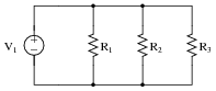
|
|
- �
- Voltage source V1 fails with increased output:
- �
- Resistor R1 fails open:
- �
- Resistor R3 fails open:
- �
- Solder bridge (short) across resistor R2:
For each of these conditions, explain why the resulting effects will occur.
- �
- Voltage source V1 fails with increased output: All resistor currents increase, all resistor voltages increase, current through V1 increases.
- �
- Resistor R1 fails open: All resistor voltages remain unchanged, current through R1 decreases to zero, currents through R2 and R3 remain unchanged, current through V1 decreases by the amount that used to go through R1.
- �
- Resistor R3 fails open: All resistor voltages remain unchanged, current through R3 decreases to zero, currents through R1 and R2 remain unchanged, current through V1 decreases by the amount that used to go through R3.
- �
- Solder bridge (short) across resistor R2: Theoretically, all resistor voltages remain unchanged while a near-infinite amount of current goes through the shorted R2. Realistically, all resistor voltages will decrease to nearly zero while the currents through R2 and V1 will increase dramatically.
Notes:
The purpose of this question is to approach the domain of circuit troubleshooting from a perspective of knowing what the fault is, rather than only knowing what the symptoms are. Although this is not necessarily a realistic perspective, it helps students build the foundational knowledge necessary to diagnose a faulted circuit from empirical data. Questions such as this should be followed (eventually) by other questions asking students to identify likely faults based on measurements.
Question 41:
Predict how all component voltages and currents in this circuit will be affected as a result of the following faults. Consider each fault independently (i.e. one at a time, no multiple faults):
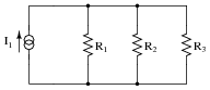
|
|
- �
- Current source I1 fails with increased output:
- �
- Resistor R1 fails open:
- �
- Resistor R3 fails open:
- �
- Solder bridge (short) across resistor R2:
For each of these conditions, explain why the resulting effects will occur.
- �
- Current source I1 fails with increased output: All resistor currents increase, all resistor voltages increase, voltage across I1 increases.
- �
- Resistor R1 fails open: All resistor voltages increase, current through R1 decreases to zero, currents through R2 and R3 increase, current through I1 remains unchanged, voltage across I1 increases.
- �
- Resistor R3 fails open: All resistor voltages increase, current through R3 decreases to zero, currents through R1 and R2 increase, current through I1 remains unchanged, voltage across I1 increases.
- �
- Solder bridge (short) across resistor R2: All resistor voltages decrease to zero, currents through R1 and R3 decrease to zero, current through shorted R2 increases to equal I1, current through I1 remains unchanged, voltage across I1 decreases to zero.
Notes:
The purpose of this question is to approach the domain of circuit troubleshooting from a perspective of knowing what the fault is, rather than only knowing what the symptoms are. Although this is not necessarily a realistic perspective, it helps students build the foundational knowledge necessary to diagnose a faulted circuit from empirical data. Questions such as this should be followed (eventually) by other questions asking students to identify likely faults based on measurements.
Question 42:
Calculate and label the currents at each node (junction point) in this circuit:
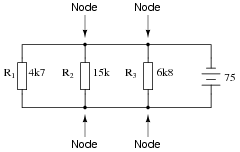
|
|
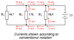
|
|
Notes:
Discuss with your students techniques for calculating the node currents. What Laws did your students apply, and more importantly, in what order did they apply them?
Question 43:
Calculate and label the currents at each node (junction point) in this circuit:
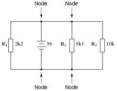
|
|
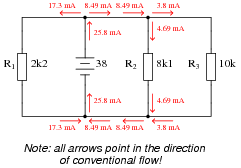
|
|
Notes:
Discuss with your students techniques for calculating the node currents. What Laws did your students apply, and more importantly, in what order did they apply them?
Question 44:
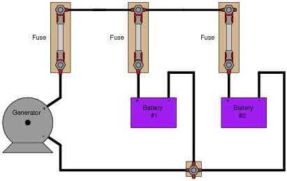
Determine the current through battery #2 in this power system, if the generator is outputting 50 amps, battery #1 is charging at a rate of 22 amps, and the light bulbs draw 5 amps of current each. Be sure to indicate whether battery #2 is charging or discharging:
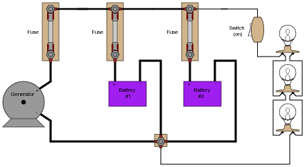
|
|
Notes:
Perhaps the most difficult portion of this question for students to figure out is which way current goes when a battery is charging, versus when it is discharging. Thus, it is a good review for students on secondary battery theory!
Another challenge for students might be where to label a "node" for the algebraic summation of currents. Do not simply tell them, but rather let them choose the node.
Question 45:
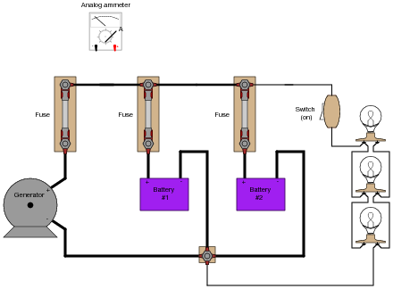
Explain how an analog ammeter could be used to measure the current output of the generator in this circuit, as it charges the two batteries and energizes the three light bulbs. Be sure to connect the ammeter in the circuit in such a way that the meter needle does not drive "downscale"!
|
|
Follow-up question: describe any relevant safety procedures and considerations necessary prior to performing this task.
Notes:
Be sure to reinforce the safety aspects of this task. Although the primary focus of this question is most definitely Kirchhoff's Current Law, that is no excuse to avoid discussing electrical safety!
Question 46:
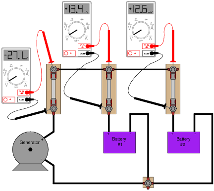
Suppose you are asked to determine whether or not each battery in this circuit is charging or discharging:
|
|
To do so, of course, you need to determine the direction of current through each battery. Unfortunately, your multimeter does not have the current rating necessary to directly measure such large currents, and you do not have access to a clamp-on (magnetic) ammeter capable of measuring DC current.
You are about to give up when a master technician comes along and uses her multimeter (set to measure millivolts) to take these three voltage measurements:
|
|
"There," she says, ït's easy!" With that, she walks away, leaving you to figure out what those measurements mean. Determine the following:
- �
- How these DC millivoltage measurements indicate direction of current.
- �
- Whether or not each battery is charging or discharging.
- �
- Whether or not these millivoltage measurements can tell you how much current is going through each battery.
- �
- How this general principle of measurement may be extended to other practical applications.
Notes:
This is a very practical (and handy!) method of qualitative current measurement I've used many times on the job. Fuses, as well as other current-handling components, always have some non-zero amount of electrical resistance between their terminals, which means they are usable as crude shunt resistors. Their actual resistance will most likely be unknown to you, which is why they are useful in this capacity as qualitative measurement devices only, not quantitative.
Some students may point out that the measurement taken across the generator's fuse is not necessary to determine battery charging status. Technically, this is true, but doing so helps to confirm the validity of this technique. The polarity of that measurement does indeed show (conventional flow) current to be going upward through the generator fuse, versus downward through the battery fuses.
Students may also point out that the battery fuse millivoltage measurements do not add up to equal the generator fuse millivoltage measurement, as Kirchhoff's Current Law (KCL) would suggest. This is one example showing how the technique is strictly qualitative, not quantitative. We have no idea how much resistance lies within each fuse, and so we cannot rely on the millivoltage measurements as being proportional to current. This is especially true if the fuses are not identical!
Other circuit elements lending themselves to this same sort of application include overload "heater" elements for motor control circuits, long lengths of wire (provided you can stretch your millivolt-meter leads to reach both ends), circuit breakers, (closed) switches, and wire connections (particularly if the connection is old and possibly corroded).
Question 47:
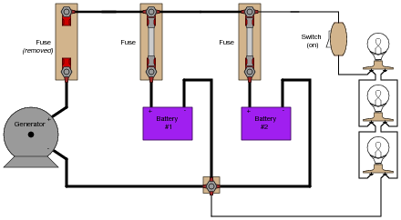
The generator in this power system is disconnected for routine servicing by removing its fuse, leaving the two batteries to supply all power to the bank of light bulbs:
|
|
The two batteries are rated such that they are supposed to provide at least 10 hours of back-up power in the event of a generator öutage" such as this. Unfortunately, the light bulbs begin to dim much sooner than expected. Something is wrong in the system, and you are asked to figure out what.
Explain what steps you would take to diagnose the problem in this circuit, commenting on any relevant safety measures taken along the way.
Notes:
I purposely avoided giving away explicit answers in the Answer section of this question, electing instead to simply provide a sound procedure. The point here is for students to figure out on their own what the voltmeter indications would mean with regard to battery condition.
Question 48:
Although the voltage divider and current divider equations are very useful in circuit analysis, they are easily confused for one another because they look so similar:
|
Specifically, it is easy to forget which way the resistance fraction goes for each one. Is it [R/(Rtotal)] or is it [(Rtotal)/R] ? Simply trying to memorize which fraction form goes with which equation is a bad policy, since memorization of arbitrary forms tends to be unreliable. What is needed is recognition of some sort of principle that makes the form of each equation sensible. In other words, each equation needs to make sense why it is the way it is.
Explain how one would be able to tell that the following equations are wrong, without referring to a book:
|
Notes:
Note that I do not explain why the fraction is less than 1 for each equation. I leave it to the students to figure out that R < Rtotal for series circuits and Rtotal < R for parallel circuits.
Many students have the unfortunate tendency to memorize in favor of understand, especially when it comes to equations. Comprehension is, of course, far superior, and exercises like this one help students build comprehension of the formulae they use in electronics.