Linear computational circuitry
Question 1:
| Don't just sit there! Build something!! |
Learning to mathematically analyze circuits requires much study and practice. Typically, students practice by working through lots of sample problems and checking their answers against those provided by the textbook or the instructor. While this is good, there is a much better way.
You will learn much more by actually building and analyzing real circuits, letting your test equipment provide the änswers" instead of a book or another person. For successful circuit-building exercises, follow these steps:
- 1.
- Carefully measure and record all component values prior to circuit construction.
- 2.
- Draw the schematic diagram for the circuit to be analyzed.
- 3.
- Carefully build this circuit on a breadboard or other convenient medium.
- 4.
- Check the accuracy of the circuit's construction, following each wire to each connection point, and verifying these elements one-by-one on the diagram.
- 5.
- Mathematically analyze the circuit, solving for all voltage and current values.
- 6.
- Carefully measure all voltages and currents, to verify the accuracy of your analysis.
- 7.
- If there are any substantial errors (greater than a few percent), carefully check your circuit's construction against the diagram, then carefully re-calculate the values and re-measure.
Avoid using the model 741 op-amp, unless you want to challenge your circuit design skills. There are more versatile op-amp models commonly available for the beginner. I recommend the LM324 for DC and low-frequency AC circuits, and the TL082 for AC projects involving audio or higher frequencies.
As usual, avoid very high and very low resistor values, to avoid measurement errors caused by meter "loading". I recommend resistor values between 1 kW and 100 kW.
One way you can save time and reduce the possibility of error is to begin with a very simple circuit and incrementally add components to increase its complexity after each analysis, rather than building a whole new circuit for each practice problem. Another time-saving technique is to re-use the same components in a variety of different circuit configurations. This way, you won't have to measure any component's value more than once.
Notes:
It has been my experience that students require much practice with circuit analysis to become proficient. To this end, instructors usually provide their students with lots of practice problems to work through, and provide answers for students to check their work against. While this approach makes students proficient in circuit theory, it fails to fully educate them.
Students don't just need mathematical practice. They also need real, hands-on practice building circuits and using test equipment. So, I suggest the following alternative approach: students should build their own "practice problems" with real components, and try to mathematically predict the various voltage and current values. This way, the mathematical theory "comes alive," and students gain practical proficiency they wouldn't gain merely by solving equations.
Another reason for following this method of practice is to teach students scientific method: the process of testing a hypothesis (in this case, mathematical predictions) by performing a real experiment. Students will also develop real troubleshooting skills as they occasionally make circuit construction errors.
Spend a few moments of time with your class to review some of the "rules" for building circuits before they begin. Discuss these issues with your students in the same Socratic manner you would normally discuss the worksheet questions, rather than simply telling them what they should and should not do. I never cease to be amazed at how poorly students grasp instructions when presented in a typical lecture (instructor monologue) format!
A note to those instructors who may complain about the "wasted" time required to have students build real circuits instead of just mathematically analyzing theoretical circuits:
What is the purpose of students taking your course?
If your students will be working with real circuits, then they should learn on real circuits whenever possible. If your goal is to educate theoretical physicists, then stick with abstract analysis, by all means! But most of us plan for our students to do something in the real world with the education we give them. The "wasted" time spent building real circuits will pay huge dividends when it comes time for them to apply their knowledge to practical problems.
Furthermore, having students build their own practice problems teaches them how to perform primary research, thus empowering them to continue their electrical/electronics education autonomously.
In most sciences, realistic experiments are much more difficult and expensive to set up than electrical circuits. Nuclear physics, biology, geology, and chemistry professors would just love to be able to have their students apply advanced mathematics to real experiments posing no safety hazard and costing less than a textbook. They can't, but you can. Exploit the convenience inherent to your science, and get those students of yours practicing their math on lots of real circuits!
Question 2:
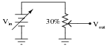
Suppose I set a potentiometer to the 30% position, so that the wiper is 30% of the way up from the bottom:
|
|
Describe the mathematical relationship between Vin and Vout with the potentiometer in this position. What does this suggest about the usefulness of a potentiometer as an analog computational element?
Notes:
The important idea in this question is for students to view a potentiometer as an adjustable divider which may be used to provide a ratio function in an analog circuit. This may be your students' first step into the world of analog computational circuitry (using voltage and current values to represent numerical quantities), so be sure to emphasize the significance of this lowly potentiometer's function. The very idea that such a simple device can actually be used to perform a mathematical operation is profound.
Question 3:
What historical significance does the name "operational amplifier" have? Of course, it should be obvious that these devices are amplifiers, but what is meant by the word operational?
Notes:
Your students should be able to find plenty of references to the historical development and use of op-amps as computational devices. Ask them where they found their information!
Question 4:
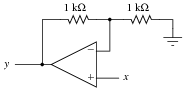
Write a mathematical expression in the form of y = ... x describing the function of this circuit:
|
|
Notes:
Your students should be able to recognize that this amplifier circuit has a voltage gain of 2, but expressing it in the form of an equation using variables such as x and y may be something very new to them. Discuss with your students the significance of this notation: that a circuit may embody an equation. Analog computers may be öbsolete" technology, but they still have many practical applications.
Question 5:
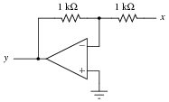
Write a mathematical expression in the form of y = ... x describing the function of this circuit:
|
|
Notes:
Your students should be able to recognize that this amplifier circuit has a voltage gain of 1, and that it is inverting in nature, but expressing it in the form of an equation using variables such as x and y may be something very new to them. Discuss with your students the significance of this notation: that a circuit may embody an equation.
Question 6:
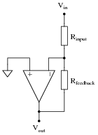
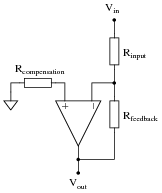
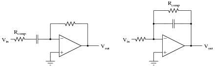
Ideally, an inverting amplifier circuit may be comprised of just one op-amp and two resistors, as such:
|
|
However, if high accuracy is desired, a third resistor must be added to the circuit, in series with the other op-amp input:
|
|
Explain what this "compensation" resistor is compensating for, and also what its value should be.
Notes:
First, your students will have to know what "bias currents" are in op-amp circuits, so begin your discussion of this question with a call for this definition. Why the compensation resistor value must be equal to the parallel equivalent of the two resistors in the voltage divider is something that confuses most students. The key to understanding it is network analysis, in particular Thévenin's and Norton's theorems.
Question 7:
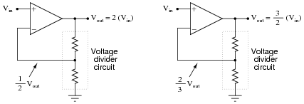
We know that an opamp connected to a voltage divider with a voltage division ratio of [1/2] will have an overall voltage gain of 2, and that the same circuit with a voltage division ratio of [2/3] will have an overall voltage gain of 1.5, or [3/2]:
|
|
There is definitely a mathematical pattern at work in these noninverting opamp circuits: the overall voltage gain of the circuit is the mathematical inverse of the feedback network's voltage gain.
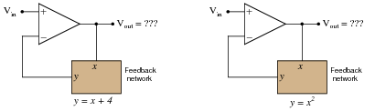
Building on this concept, what do you think would be the overall function of the following opamp circuits?
|
|
|
|
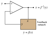
The result of placing a mathematical function in the feedback loop of a noninverting opamp circuit is that the output becomes the inverse function of the input: it literally becomes the value of x needed to solve for the input value of y:
|
|
Notes:
What is shown in this question and answer is a stark example of the power of negative feedback in a mathematical system. Here, we see the opamp's ability to solve for the input variable in an equation which we know the output value of. To state this in simpler terms, the opamp "does algebra" for us by "manipulating" the feedback network's equation to solve for x given an input signal of y.
Question 8:
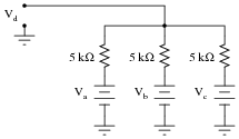
The simple resistor network shown here is known as a passive averager. Describe what the word "passive" means in this context, and write an equation describing the output voltage (Vd) in terms of the input voltages (Va, Vb, and Vc):
|
|
Hint: there is a network theorem that directly applies to this form of circuit, and it is known as Millman's Theorem. Research this theorem and use it to generate your equation!
|
Notes:
Students need to realize that even passive circuits are able to model (some) mathematical functions! Ask your students if they can think of any network analysis methods to easily calculate the output voltage (Vd) of this circuit, given the input voltages. There is one theorem in particular that works very well for this particular circuit.
Question 9:
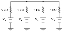
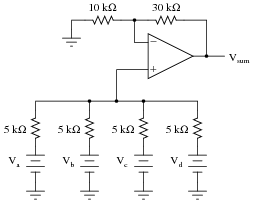
Add an op-amp circuit to the output of this passive averager network to produce a summer circuit: an operational circuit generating an output voltage equal to the sum of the four input voltages. Then, write an equation describing the whole circuit's function.
|
|
|
|
|
Notes:
The equation for this circuit is simple enough as to require no explanation. How your students derived this equation, from the base equation of a passive averager network, on the other hand, is worth discussion. Discuss with them the necessary gain of the op-amp circuit, and how this gain figure converts an averaging function into a summing function.
Question 10:
Write a mathematical equation for this op-amp circuit, assuming all resistor values are equal:
|
|
What is this circuit typically called?
This type of circuit is typically called an inverting summer.
Follow-up question: explain why the addition of another resistor in this circuit is recommended for optimum accuracy, as shown in the following schematic.
|
|
Challenge question: write an equation describing the proper value of this extra resistor.
Notes:
Ask your students about the proper resistor values for an inverting summer circuit. The choices of resistor values are definitely not the same for inverting summer and noninverting summer circuits alike! Discuss why the values are what they are in an inverting summer circuit (using Ohm's Law to analyze the circuit's function), emphasizing comprehension over rote memorization.
Question 11:
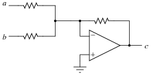
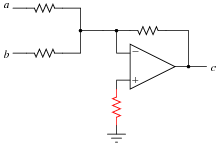
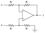
This opamp circuit is known as a difference amplifier, sometimes called a subtractor. Assuming that all resistor values are equal in the circuit, write an equation expressing the output (y) as a function of the two input voltages (a and b):
|
|
Notes:
Work through some example conditions of input voltages and resistor values to calculate the output voltage using Ohm's Law and the general principle of negative feedback in an opamp circuit (namely, an assumption of zero voltage differential at the opamp inputs). The goal here is to have students comprehend why this circuit subtracts one voltage from another, rather than just encourage rote memorization.
Question 12:
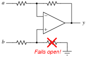
Re-write the equation for this differential amplifier circuit, assuming that the marked resistor fails open:
|
|
Notes:
Ask your students to explain how they would verify the failure of the marked resistor, using a voltmeter (not an ohmmeter!).
Question 13:
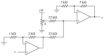
Write a mathematical expression in the form of y = ... x describing the function of this circuit:
|
|
Notes:
In this circuit, we combine two different op-amp functions into one system, embodying a linear equation. Discuss with your students what circuit alterations would be required to change the coefficients of this equation.
If it helps some of your students understand the overall function of this circuit better, you might want to ask other students to outline which groups of components in this circuit perform which portion of the equation (while the circuit schematic is displayed on the whiteboard for all to see).
Question 14:
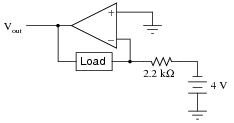
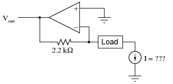
How much current will go through the load in this op-amp circuit?
|
|
What impact will a change in load resistance have on the operation of this circuit? What will change, if anything, supposing the load resistance were to increase?
If the load changes resistance, there will be no effect on the amount of current through it, although there will be an effect on the output voltage of the opamp!
Notes:
The purpose of this question, besides giving students reason to review a constant-current opamp circuit, is to preview the behavior of an active integrator using the same resistor and input voltage values (question #01008).
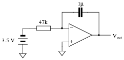
Question 15:
|
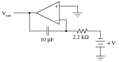
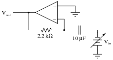
How much current will go "through" the capacitor in this op-amp circuit, and what effect does this have on the output voltage?
|
|
This circuit is an integrator: its output voltage changes over time at a rate proportional to the input voltage magnitude.
Follow-up question: what is the output voltage rate-of-change over time ([dv/dt]) for the circuit shown in the question?
Notes:
This question is a good review of capacitor theory (relating voltage and current with regard to a capacitor), as well as an introduction to how op-amp circuits can perform calculus functions.
Challenge your students to calculate the output [dv/dt] without using a calculator!
Question 16:
What will the output voltage of this integrator circuit do when the DPDT ("Double-Pole, Double-Throw") switch is flipped back and forth?
|
|
Be as specific as you can in your answer, explaining what happens in the switch's üp" position as well as in its "down" position.
Follow-up question: what do you suppose the output of the following circuit would do over time (assuming the square wave input was true AC, positive and negative)?
|
|
Notes:
The DPDT switch arrangement may be a bit confusing, but its only purpose is to provide a reversible input voltage polarity. Discuss with your students the directions of all currents in this circuit for both switch positions, and how the opamp output integrates over time for different input voltages.
Question 17:
Calculate the output voltage rate-of-change ([dv/dt]) for this active integrator circuit, being sure to explain all the steps involved in determining the answer:
|
|
Notes:
Ask your students to relate the capacitive Öhm's Law" equation to their solutions:
|
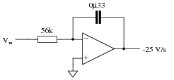
Question 18:
Calculate the input voltage needed to produce an output voltage rate-of-change ([dv/dt]) of -25 volts per second in this active integrator circuit:
|
|
Notes:
Ask your students to relate the capacitive Öhm's Law" equation to their solutions:
|
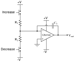
Question 19:
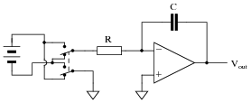
The purpose of this circuit is to provide a pushbutton-adjustable voltage. Pressing one button causes the output voltage to increase, while pressing the other button causes the output voltage to decrease. When neither button is pressed, the voltage remains stable. Essentially, it is an active integrator circuit, with resistors R1 and R2 and capacitor C1 setting the rates of integration:
|
|
After working just fine for quite a long while, the circuit suddenly fails: now it only outputs zero volts DC all the time. Identify at least one component or wiring failure that would account for the circuit's faulty behavior, and explain why that fault would cause the circuit to act like this.
Challenge question: why do you suppose I specify a CA3130 operational amplifier for this particular circuit? What is special about this opamp that qualifies it for the task?
Notes:
I purposely omitted the explanations for the possible faults listed in the answer, because I want the students to think this through, and to do so in class with you present so you may hear their reasoning.
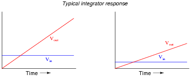
Question 20:
|
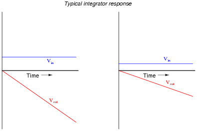
Integrator circuits may be understood in terms of their response to DC input signals: if an integrator receives a steady, unchanging DC input voltage signal, it will output a voltage that changes with a steady rate over time. The rate of the changing output voltage is directly proportional to the magnitude of the input voltage:
|
|
A symbolic way of expressing this input/output relationship is by using the concept of the derivative in calculus (a rate of change of one variable compared to another). For an integrator circuit, the rate of output voltage change over time is proportional to the input voltage:
|
A more sophisticated way of saying this is, "The time-derivative of output voltage is proportional to the input voltage in an integrator circuit." However, in calculus there is a special symbol used to express this same relationship in reverse terms: expressing the output voltage as a function of the input. For an integrator circuit, this special symbol is called the integration symbol, and it looks like an elongated letter "S":
|
Here, we would say that output voltage is proportional to the time-integral of the input voltage, accumulated over a period of time from time=0 to some point in time we call T.
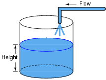
"This is all very interesting," you say, "but what does this have to do with anything in real life?" Well, there are actually a great deal of applications where physical quantities are related to each other by time-derivatives and time-integrals. Take this water tank, for example:
|
|
One of these variables (either height H or flow F, I'm not saying yet!) is the time-integral of the other, just as Vout is the time-integral of Vin in an integrator circuit. What this means is that we could electrically measure one of these two variables in the water tank system (either height or flow) so that it becomes represented as a voltage, then send that voltage signal to an integrator and have the output of the integrator derive the other variable in the system without having to measure it!
Your task is to determine which variable in the water tank scenario would have to be measured so we could electronically predict the other variable using an integrator circuit.
Notes:
Your more alert students will note that the output voltage for a simple integrator circuit is of inverse polarity with respect to the input voltage, so the graphs should really look like this:
|
|
I have chosen to express all variables as positive quantities in order to avoid any unnecessary confusion as students attempt to grasp the concept of time integration.
Question 21:
|
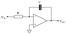
We know that the output of an integrator circuit is proportional to the time-integral of the input voltage:
|
|
|
But how do we turn this proportionality into an exact equality, so that it accounts for the values of R and C? Although the answer to this question is easy enough to simply look up in an electronics reference book, it would be great to actually derive the exact equation from your knowledge of electronic component behaviors! Here are a couple of hints:
|
|
Follow-up question: why is there a negative sign in the equation?
Notes:
The two "hint" equations given at the end of the question beg for algebraic substitution, but students must be careful which variable(s) to substitute! Both equations contain an I, and both equations also contain a V. The answer to that question can only be found by looking at the schematic diagram: do the resistor and capacitor share the same current, the same voltage, or both?
Question 22:
|
If an object moves in a straight line, such as an automobile traveling down a straight road, there are three common measurements we may apply to it: position (x), velocity (v), and acceleration (a). Position, of course, is nothing more than a measure of how far the object has traveled from its starting point. Velocity is a measure of how fast its position is changing over time. Acceleration is a measure of how fast the velocity is changing over time.
These three measurements are excellent illustrations of calculus in action. Whenever we speak of "rates of change," we are really referring to what mathematicians call derivatives. Thus, when we say that velocity (v) is a measure of how fast the object's position (x) is changing over time, what we are really saying is that velocity is the "time-derivative" of position. Symbolically, we would express this using the following notation:
|
Likewise, if acceleration (a) is a measure of how fast the object's velocity (v) is changing over time, we could use the same notation and say that acceleration is the time-derivative of velocity:
|
Since it took two differentiations to get from position to acceleration, we could also say that acceleration is the second time-derivative of position:
|
"What has this got to do with electronics," you ask? Quite a bit! Suppose we were to measure the velocity of an automobile using a tachogenerator sensor connected to one of the wheels: the faster the wheel turns, the more DC voltage is output by the generator, so that voltage becomes a direct representation of velocity. Now we send this voltage signal to the input of a differentiator circuit, which performs the time-differentiation function on that signal. What would the output of this differentiator circuit then represent with respect to the automobile, position or acceleration? What practical use do you see for such a circuit?
Now suppose we send the same tachogenerator voltage signal (representing the automobile's velocity) to the input of an integrator circuit, which performs the time-integration function on that signal (which is the mathematical inverse of differentiation, just as multiplication is the mathematical inverse of division). What would the output of this integrator then represent with respect to the automobile, position or acceleration? What practical use do you see for such a circuit?
|
|
Follow-up question: draw the schematic diagrams for these two circuits (differentiator and integrator).
Notes:
The calculus relationships between position, velocity, and acceleration are fantastic examples of how time-differentiation and time-integration works, primarily because everyone has first-hand, tangible experience with all three. Everyone inherently understands the relationship between distance, velocity, and time, because everyone has had to travel somewhere at some point in their lives. Whenever you as an instructor can help bridge difficult conceptual leaps by appeal to common experience, do so!
Question 23:
|
A familiar context in which to apply and understand basic principles of calculus is the motion of an object, in terms of position (x), velocity (v), and acceleration (a). We know that velocity is the time-derivative of position (v = [dx/dt]) and that acceleration is the time-derivative of velocity (a = [dv/dt]). Another way of saying this is that velocity is the rate of position change over time, and that acceleration is the rate of velocity change over time.
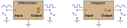
It is easy to construct circuits which input a voltage signal and output either the time-derivative or the time-integral (the opposite of the derivative) of that input signal. We call these circuits "differentiators" and ïntegrators," respectively.
|
|
Integrator and differentiator circuits are highly useful for motion signal processing, because they allow us to take voltage signals from motion sensors and convert them into signals representing other motion variables. For each of the following cases, determine whether we would need to use an integrator circuit or a differentiator circuit to convert the first type of motion signal into the second:
- �
- Converting velocity signal to position signal: (integrator or differentiator?)
- �
- Converting acceleration signal to velocity signal: (integrator or differentiator?)
- �
- Converting position signal to velocity signal: (integrator or differentiator?)
- �
- Converting velocity signal to acceleration signal: (integrator or differentiator?)
- �
- Converting acceleration signal to position signal: (integrator or differentiator?)
Also, draw the schematic diagrams for these two different circuits.
- �
- Converting velocity signal to position signal: (integrator)
- �
- Converting acceleration signal to velocity signal: (integrator)
- �
- Converting position signal to velocity signal: (differentiator)
- �
- Converting velocity signal to acceleration signal: (differentiator)
- �
- Converting acceleration signal to position signal: (two integrators!)
I'll let you figure out the schematic diagrams on your own!
Notes:
The purpose of this question is to have students apply the concepts of time-integration and time-differentiation to the variables associated with moving objects. I like to use the context of moving objects to teach basic calculus concepts because of its everyday familiarity: anyone who has ever driven a car knows what position, velocity, and acceleration are, and the differences between them.
One way I like to think of these three variables is as a verbal sequence:

|
|
Arranged as shown, differentiation is the process of stepping to the right (measuring the rate of change of the previous variable). Integration, then, is simply the process of stepping to the left.
Ask your students to come to the front of the class and draw their integrator and differentiator circuits. Then, ask the whole class to think of some scenarios where these circuits would be used in the same manner suggested by the question: motion signal processing. Having them explain how their schematic-drawn circuits would work in such scenarios will do much to strengthen their grasp on the concept of practical integration and differentiation.
Question 24:
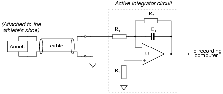
This active integrator circuit processes the voltage signal from an accelerometer, a device that outputs a DC voltage proportional to its physical acceleration. The accelerometer is being used to measure the acceleration of an athlete's foot as he kicks a ball, and the job of the integrator is to convert that acceleration signal into a velocity signal so the researchers can record the velocity of the athlete's foot:
|
|
During the set-up for this test, a radar gun is used to check the velocity of the athlete's foot as he does come practice kicks, and compare against the output of the integrator circuit. What the researchers find is that the integrator's output is reading a bit low. In other words, the integrator circuit is not integrating fast enough to provide an accurate representation of foot velocity.
Determine which component(s) in the integrator circuit may have been improperly sized to cause this calibration problem. Be as specific as you can in your answer(s).
Notes:
This is an interesting, practical question regarding the use of an integrator circuit for real-life signal processing. Ask your students to explain their reasoning as they state their proposed component faults.
Incidentally, if anyone asks what the purpose of R2 or R3 is, tell them that both are used for opamp bias current compensation. An ideal opamp would not require these components to be in place.
Question 25:
How much current (I) would have to be forced through the resistor in order to generate an output voltage of 5 volts?
|
|
Notes:
The purpose of this question, besides giving students reason to review a current-to-voltage converter opamp circuit, is to preview the behavior of an active differentiator using the same resistor and output voltage values (question #02698).
Question 26:
|
How much current (I) would have to be forced through the resistor in order to generate an output voltage of 5 volts?
|
|
At what rate would Vin have to increase in order to cause this amount of current to go "through" the capacitor, and thereby cause 5 volts to appear at the Vout terminal? What does this tell us about the behavior of this circuit?
The fact that this circuit outputs a voltage proportional to the rate of change over time of the input voltage indicates that it is a differentiator.
Notes:
This question is a good review of capacitor theory (relating voltage and current with regard to a capacitor), as well as an introduction to how op-amp circuits can perform calculus functions.
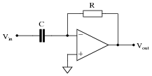
Question 27:
|
We know that the output of a differentiator circuit is proportional to the time-derivative of the input voltage:
|
|
|
But how do we turn this proportionality into an exact equality, so that it accounts for the values of R and C? Although the answer to this question is easy enough to simply look up in an electronics reference book, it would be great to actually derive the exact equation from your knowledge of electronic component behaviors! Here are a couple of hints:
|
|
Follow-up question: why is there a negative sign in the equation?
Notes:
The two "hint" equations given at the end of the question beg for algebraic substitution, but students must be careful which variable(s) to substitute! Both equations contain an I, and both equations also contain a V. The answer to that question can only be found by looking at the schematic diagram: do the resistor and capacitor share the same current, the same voltage, or both?
Question 28:
|
You are part of a team building a rocket to carry research instruments into the high atmosphere. One of the variables needed by the on-board flight-control computer is velocity, so it can throttle engine power and achieve maximum fuel efficiency. The problem is, none of the electronic sensors on board the rocket has the ability to directly measure velocity. What is available is an altimeter, which infers the rocket's altitude (it position away from ground) by measuring ambient air pressure; and also an accelerometer, which infers acceleration (rate-of-change of velocity) by measuring the inertial force exerted by a small mass.
The lack of a ßpeedometer" for the rocket may have been an engineering design oversight, but it is still your responsibility as a development technician to figure out a workable solution to the dilemma. How do you propose we obtain the electronic velocity measurement the rocket's flight-control computer needs?
Notes:
This question simply puts students' comprehension of basic calculus concepts (and their implementation in electronic circuitry) to a practical test.
Question 29:
|
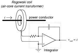
A Rogowski Coil is essentially an air-core current transformer that may be used to measure DC currents as well as AC currents. Like all current transformers, it measures the current going through whatever conductor(s) it encircles.
Normally transformers are considered AC-only devices, because electromagnetic induction requires a changing magnetic field ([(d f)/dt]) to induce voltage in a conductor. The same is true for a Rogowski coil: it produces a voltage only when there is a change in the measured current. However, we may measure any current (DC or AC) using a Rogowski coil if its output signal feeds into an integrator circuit as shown:
|
|
Connected as such, the output of the integrator circuit will be a direct representation of the amount of current going through the wire.
Explain why an integrator circuit is necessary to condition the Rogowski coil's output so that output voltage truly represents conductor current.
|
Review question: Rogowski coils are rated in terms of their mutual inductance (M). Define what "mutual inductance" is, and why this is an appropriate parameter to specify for a Rogowski coil.
Follow-up question: the operation of a Rogowski coil (and the integrator circuit) is probably easiest to comprehend if one imagines the measured current starting at 0 amps and linearly increasing over time. Qualitatively explain what the coil's output would be in this scenario and then what the integrator's output would be.
Challenge question: the integrator circuit shown here is an äctive" integrator rather than a "passive" integrator. That is, it contains an amplifier (an äctive" device). We could use a passive integrator circuit instead to condition the output signal of the Rogowski coil, but only if the measured current is purely AC. A passive integrator circuit would be insufficient for the task if we tried to measure a DC current - only an active integrator would be adequate to measure DC. Explain why.
Notes:
This question provides a great opportunity to review Faraday's Law of electromagnetic induction, and also to apply simple calculus concepts to a practical problem. The coil's natural function is to differentiate the current going through the conductor, producing an output voltage proportional to the current's rate of change over time (vout � [(diin)/dt]). The integrator's function is just the opposite. Discuss with your students how the integrator circuit ündoes" the natural calculus operation inherent to the coil (differentiation).
The subject of Rogowski coils also provides a great opportunity to review what mutual inductance is. Usually introduced at the beginning of lectures on transformers and quickly forgotten, the principle of mutual inductance is at the heart of every Rogowski coil: the coefficient relating instantaneous current change through one conductor to the voltage induced in an adjacent conductor (magnetically linked).
|
Unlike the iron-core current transformers (CT's) widely used for AC power system current measurement, Rogowski coils are inherently linear. Being air-core devices, they lack the potential for saturation, hysteresis, and other nonlinearities which may corrupt the measured current signal. This makes Rogowski coils well-suited for high frequency (even RF!) current measurements, as well as measurements of current where there is a strong DC bias current in the conductor. By the way, this DC bias current may be "nulled" simply by re-setting the integrator after the initial DC power-up!
If time permits, this would be an excellent point of departure to other realms of physics, where op-amp signal conditioning circuits can be used to ündo" the calculus functions inherent to certain physical measurements (acceleration vs. velocity vs. position, for example).
Question 30:
|
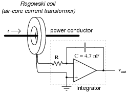
A Rogowski coil has a mutual inductance rating of 5 mH. Calculate the size of the resistor necessary in the integrator circuit to give the integrator output a 1:1 scaling with the measured current, given a capacitor size of 4.7 nF:
|
|
That is, size the resistor such that a current through the conductor changing at a rate of 1 amp per second will generate an integrator output voltage changing at a rate of 1 volt per second.
Notes:
This question not only tests students' comprehension of the Rogowski coil and its associated calculus (differentiating the power conductor current, as well as the need to integrate its output voltage signal), but it also tests students' quantitative comprehension of integrator circuit operation and problem-solving technique. Besides, it gives some practical context to integrator circuits!
Question 31:
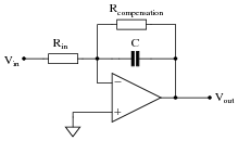
Practical integrator circuits must have a compensating resistor connected in parallel with the capacitor, in the feedback loop. Typically, this resistor value is very large: about 100 times as large as Rin.
|
|
Describe why this is a necessity for accurate integration. Hint: an ideal opamp would not need this resistor!
Notes:
Discuss where bias currents originate from in the opamp's internal circuitry, and ask your students if they have any recommendations on specific opamp types that minimize bias current.
Question 32:
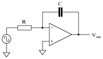
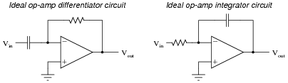
Practical op-amp integrator and differentiator circuits often cannot be built as simply as their "textbook" forms usually appear:
|
|
The voltage gains of these circuits become extremely high at certain signal frequencies, and this may cause problems in real circuitry. A simple way to "tame" these high gains to moderate levels is to install an additional resistor in each of the circuits, as such:
|
|
The purpose of each resistor is to "dominate" the impedance of the RC network as the input signal frequency approaches the point at which problems would occur in the ideal versions of the circuits. In each of these "compensated" circuits, determine whether the value of the compensation resistor needs to be large or small compared to the other resistor, and explain why.
Of course, this solution is not without problems of its own. By adding this new resistor to each circuit, a half-power (-3 dB) cutoff frequency point is created by the interaction of the compensation resistor and the capacitor, as predicted by the equation fc = [1/(2 pRcompC)]. The value predicted by this equation establishes a practical limit for the differentiation and integration functions, respectively. Operating on the wrong side of the frequency limit will result in an output waveform that is not the true time-derivative or time-integral of the input waveform. Determine whether the fc value constitutes a low frequency limit or a high frequency limit for each circuit, and explain why.
For the integrator circuit, Rcomp >> Rinput, and [1/(2 pRcompC)] is a low frequency limit.
Notes:
In order to successfully answer the questions, students will need a firm grasp on the nature of the gain problem with differentiator and integrator circuits. This is based on an understanding of capacitive reactance, and the relationship between op-amp gain and input/feedback impedances. These are not difficult questions to answer, if one takes an orderly and methodical approach to the problem. Help your students reason through to the correct answers by asking questions that challenge them to link concepts of op-amp feedback gain, capacitive reactance, impedances of series and parallel RC networks, etc.
Question 33:
|
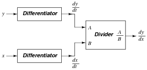
The chain rule of calculus states that:
|
Similarly, the following mathematical principle is also true:
|
It is very easy to build an opamp circuit that differentiates a voltage signal with respect to time, such that an input of x produces an output of [dx/dt], but there is no simple circuit that will output the differential of one input signal with respect to a second input signal.
However, this does not mean that the task is impossible. Draw a block diagram for a circuit that calculates [dy/dx], given the input voltages x and y. Hint: this circuit will make use of differentiators.
Challenge question: draw a full opamp circuit to perform this function!
|
|
Notes:
Differentiator circuits are very useful devices for making "live" calculations of time-derivatives for variables represented in voltage form. Explain to your students, for example, that the physical measurement of velocity, when differentiated with respect to time, is acceleration. Thus, a differentiator circuit connected to a tachogenerator measuring the speed of something provides a voltage output representing acceleration.
Being able to differentiate one signal in terms of another, although equally useful in physics, is not so easy to accomplish with opamps. A question such as this one highlights a practical use of calculus (the "chain rule"), where the differentiator circuit's natural function is exploited to achieve a more advanced function.
Question 34:
Draw the appropriate wires in this diagram to complete the circuit for a differentiator circuit (the opposite function of an integrator circuit):
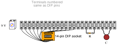
|
|
The particular opamp used in this circuit is an LM324 (quad) operational amplifier. Of course, you need only show how one of the four opamps within the IC may be connected to form a differentiator.
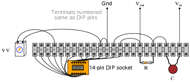
|
|
Challenge question: given the single-supply configuration (+9 volts only), this differentiator circuit can only respond to one direction of input voltage change ([(dvin)/dt]). Which direction is this: positive or negative?
Notes:
As always with problems centered around a pictorial diagram, the solution is more apparent if a schematic diagram is drawn as a "map" first. Ask your students to explain how they transitioned from the original diagram, to their own schematic, back to a completed diagram.
Also discuss the similarities between differentiator circuits and integrator circuits. The two mathematical functions are inverse operations of each other. How is this symmetry reflected in the respective circuit configurations?
Question 35:
Analog computers have been all but replaced by digital computers in modern electronic systems. Yet, analog computational circuits still enjoy certain advantages over digital circuits. Describe what some of the limitations of analog computers are, and why these limitations have led to their obsolescence. Also, discuss some of the advantages of analog computers, and why a designer might still choose to use an analog computational circuit in a modern system.
Notes:
I like to introduce analog computational circuits to beginning electronics students because of their elegant simplicity, and for the fact that they greatly help to "link" the abstract world of mathematics to real mechanisms. Students are generally excited to realize they can build an actual computer with just a handful of inexpensive electronic components.