Magnetic units of measurement
Question 1:
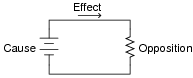
In electric circuits, the three basic quantities are voltage (E or V), current (I), and resistance (R), corresponding to the general concepts of cause, effect, and opposition, respectively.
|
|
|
|
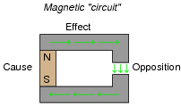
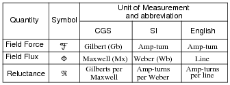
Magnetic "circuits" also have quantities corresponding to "cause," ëffect," and öpposition." Identify these quantities, along with their respective symbols, and write an Öhm's Law" equation relating them mathematically. Also, identify the units of measurement associated with each, in three systems of measurement: CGS (öld" metric), SI ("new" metric), and English.
|
|
Ëffect" = Magnetic flux = F
Öpposition" = Reluctance = �
This relationship is known as Rowland's Law, and it bears striking similarity to Ohm's Law in electric circuits:
|
|
|
Follow-up question: algebraically manipulate the Rowland's Law equation shown above to solve for F and to solve for �.
Notes:
Magnetism, while commonly experienced in the form of permanent magnets and magnetic compasses, is just as ßtrange" a concept as electricity for the new student. At this point in their education, however, they should be familiar enough with voltage, current, and resistance to reflect upon them as analogous quantities to these new magnetic quantities of MMF, flux, and reluctance. Emphasize the analogical similarities of basic electrical quantities in your discussion with students. Not only will this help students understand magnetism better, but it will also reinforce their comprehension of electrical quantities.
Question 2:
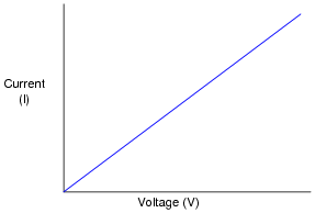
If we were to graph the "response" of a resistor to various levels of applied voltage, we would obtain a plot that looks like this:
|
|
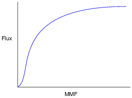
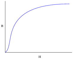
If we were to graph the "response" of a ferromagnetic sample to various levels of applied magnetomotive force, we would obtain a plot that looks something like this:
|
|
What does this graph indicate to you, as compared to the graph for a resistor's characteristics? What is the significance of this with regard to magnetic "circuit" analysis?
Notes:
Ask your students to identify resistance on the V/I graph shown in the question. Where on that graph is resistance represented? Your more mathematically astute students will recognize (or perhaps recall from earlier discussions) that the slope of the plot indicates the resistance of the circuit. The less resistance, the steeper the plot (at least in this case, where current is on the vertical axis and voltage on the horizontal). At any point on the plot, the slope is the same, indicating that resistance does not change over a wide range of voltage and current.
Now, direct their attention to the MMF/flux graph. Where is reluctance indicated on the graph? What conclusion may we form regarding reluctance in a magnetic circuit, from analyzing the shape of the MMF/flux curve shown? At what point is reluctance the greatest? At what point is it the least?
Question 3:
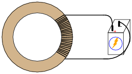
Suppose that a length of electrical wire is wrapped around a section of an iron torus, and electric current conducted through the wire:
|
|
What factors influence the amount of MMF, flux, and reluctance in this magnetic "circuit"?
Follow-up question: how similar are these relationships to voltage, resistance, and current in an electrical circuit? Note any similarities as well as any differences.
Notes:
Perhaps the most interesting part of the answer to this question is that magnetic reluctance (�) changes with the amount of flux (F) in the "circuit". At first, this may seem quite different from electrical circuits, where resistance (R) is constant regardless of current (I).
However, the constancy of electrical resistance is something easily taken for granted. Ask your students to think of electrical devices (or phenomena) where resistance is not stable over a wide range of currents. After some discussion, you should find that the phenomenon of constant resistance is not as common as one might think!
After students have grasped this concept, ask them what it means with regard to magnetic flux (F) versus MMF (F). In other words, what happens to flux in a magnetic circuit as MMF is increased?
Question 4:
Calculate the reluctance (�) for a magnetic circuit where the MMF (F) is 8.9 amp-turns and the flux (F) is 0.24 webers.
Notes:
Nothing special here, just a simple calculation. One of the points of this question is to have students research Rowland's Law and learn how to use it as they would Ohm's Law.
Question 5:
Calculate the amount of magnetic flux (F) in a piece of iron with a reluctance (�) of 55 amp-turns per weber and an applied MMF (F) of 2.2 amp-turns.
Notes:
Nothing special here, just a simple calculation. One of the points of this question is to have students research Rowland's Law and learn how to use it as they would Ohm's Law.
Note that the unit abbreviation for "webers" contains two letters, not just one as is the case for most unit abbreviations!
Question 6:
Calculate the amount of magnetomotive force (MMF, or F) required to establish a magnetic flux (F) of 30 mWb in a piece of iron having a reluctance (�) of 14 At/Wb.
Notes:
Nothing special here, just a simple calculation. One of the points of this question is to have students research Rowland's Law and learn how to use it as they would Ohm's Law.
Note that the unit abbreviation for "webers" contains two letters, not just one as is the case for most unit abbreviations!
Question 7:
Calculate the amount of MMF (F) generated by a coil of wire having 1300 turns and carrying 3.5 milliamperes of current.
Notes:
Nothing special here, just a simple calculation. One of the points of this question is to have students research the formula for calculating F, as simple as it is.
Question 8:
Calculate the number of "turns" (wraps) a wire coil would need in order to produce an MMF (F) of 5.7 amp-turns with an electric current of 12 mA.
Notes:
Nothing special here, just a simple calculation. One of the points of this question is to have students research the formula for calculating F, as simple as it is.
Question 9:
Calculate the amount of electric current that would have to pass through a coil of wire having 850 turns to produce an MMF (F) of 2.1 amp-turns.
Notes:
Nothing special here, just a simple calculation. One of the points of this question is to have students research the formula for calculating F, as simple as it is.
Question 10:
The formula for calculating the reluctance (�) of an air-core wire coil (ßolenoid") is as follows:
|
Where,
l = linear length of coil in meters (m)
A = cross-sectional area of coil "throat" in square meters (m2)
m0 = permeability of free space = 4 p × 10-7 (T·m/A)
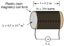
Using this formula and the Rowland's Law formula, calculate the amount of magnetic flux (F) produced in the throat of an air-core solenoid with 250 turns of wire, a length of 0.2 meters, a cross-sectional area of 6.5 × 10⁻⁴ square meters, and a coil current of 5 amps:
|
|
Notes:
With all the information given, this is nothing more than an exercise in calculation. However, it is nice for students to have the air-core solenoid reluctance formula handy for other calculations, which is the main point of this question.
Question 11:
Electrically conductive materials may be rated according to their relative resistance by a quantity we call specific resistance (r). The formula relating resistance to specific resistance looks like this:
|
Where,
R = Electrical resistance, in ohms
r = Specific resistance, in ohm-cmil/ft, or some other combination of units
l = Length of conductor, in feet or cm (depending on units for r)
A = Cross-sectional area of conductor, in cmil or cm2 (depending on units for r)
Magnetic materials may also be rated according to their relative reluctance by a quantity we call permeability (m). Write the formula relating reluctance to permeability of a magnetic substance, and note whatever differences and similarities you see between it and the specific resistance formula for electrical circuits.
|
Notes:
Ask your students to describe the effects on magnetic reluctance resulting from increases and decreases in all three independent variables (m, l, and A). It is important for them to qualitatively grasp this equation, just as it is important for them to qualitatively understand Ohm's Law and the specific resistance formula.
Question 12:
Explain the difference between relative permeability (mr) and absolute permeability (m). How do the units of measurement differ between these two quantities?
Absolute permeability is measured in units of Webers per Amp-meter (Wb/Am), while relative permeability has no unit at all.
Notes:
Ask your students to explain why relative permeability (mr) is unitless. Are there any other variables they've encountered in their science studies that are similarly unitless?
Did any of your students research the value of absolute permeability of free space (m0)? If so, what figure did they obtain?
Question 13:
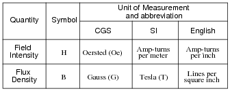
Two important variables in magnetic circuit analysis are B and H. Explain what these two variables represent, in terms of the more fundamental magnetic quantities of MMF (F) and flux (F), and relate them, if possible, to electrical quantities. Also, determine the units of measurement for these two variables, in the CGS, SI, and English measurement systems.
|
|
Field intensity (H) is also known as "magnetizing force," and is the amount of MMF per unit length of the magnetic flux path. Flux density (B) is the amount of magnetic flux per unit area.
Notes:
Although the equivalent electrical variables to field intensity and flux density are not commonly used in electronics, they do exist! Ask your students if anyone was able to determine what these variables are. Also, ask them where they were able to obtain the information on magnetic quantities and units of measurement.
You should mention to your students that the SI units are considered to be the most "modern" of those shown here, the SI system being the international standard for metric units in all applications.
Question 14:
When a steel manufacturer publishes the magnetic characteristics of their latest alloy, they do so in the form of a "B/H" graph, where flux density (B) is plotted as a function of magnetizing force (H):
|
|
Rarely will you see a plot of flux (F) shown as as a function of MMF (F), even though such a plot would appear very similar to the "B/H curve" for that same material. Why is this? Why would a "B/H" curve be preferable to an engineer rather than a "Flux/MMF" curve?
Hint: if a copper manufacturer were to publish the electrical characteristics of their latest alloy, they would specify its resistivity in terms of specific resistance (r), rather than plain resistance (R), for the exact same reason!
Notes:
This concept may confuse some students, so discussion on it is helpful. Ask your students what "flux density" and "magnetizing force" really mean: they are expressions of flux and MMF per unit dimension. So, if a manufacturer states that their new steel alloy will permit a flux density of 0.6 Tesla for an applied magnetizing force of 100 amp-turns/meter, this figure holds true for any size chunk of that alloy.
To prove this concept via the rhetorical technique of reductio ad absurdum, ask your students what it would be like if copper manufacturers specified the resistivity of their copper alloys in ohms: Älloy 123XYZ has a resistivity of 17 ohms." Of what usefulness is this statement? What does it mean to us? How is the statement, Älloy 123XYZ has a resistivity of 10.5 ohm-cmil per foot," superior?
Question 15:
Given the following equations, derive a single equation expressing permeability (m) in terms of flux density (B) and field intensity (H, otherwise known as magnetizing force):
|
|
|
|
|
Notes:
This question is an exercise in algebraic substitution and manipulation. It might be a good idea to point out that the following equation is valid only for a ßolenoid" (a coil of wire).
|
In the case of an air-core solenoid, the formula is as follows:
|
Where,
l = linear length of coil in meters (m)
A = cross-sectional area of coil "throat" in square meters (m2)
m0 = permeability of free space = 4 p × 10-7 (T·m/A)
Question 16:
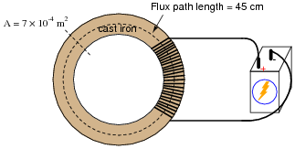
Using a B-H curve obtained from a reference book, determine the amount of magnetizing force (H) required to establish a magnetic flux density of 0.2 T in a cast iron torus with a cross-sectional area of 7 ×10⁻⁴ square meters.
|
|
Calculate the amount of current necessary in the wire coil to establish this amount of flux, if the coil has 250 turns, and the torus has an average flux path length of 45 cm. Also, calculate the amount of magnetic flux (F) inside the torus.
I = 720 mA
F = 1.4 mWb
Notes:
I obtained the magnetizing force figure of 400 At/m for 0.2 T of flux density, from Robert L. Boylestad's 9th edition of Introductory Circuit Analysis, page 437.