Microcontroller principles
Question 1:
Read the following quotation, and then research the term microcontroller to see what relevance it has to the quote:
- I went to my first computer conference at the New York Hilton about 20 years ago. When somebody there predicted the market for microprocessors would eventually be in the millions, someone else said, "Where are they all going to go? It's not like you need a computer in every doorknob!"
Years later, I went back to the same hotel. I noticed the room keys had been replaced by electronic cards you slide into slots in the doors.
There was a computer in every doorknob.
- Danny Hillis
Notes:
Not only is the quotation funny, but it is startling as well, especially to those of us who were born without any computers in our homes at all, much less multiple personal computers.
A point I wish to make in having students research the term "microcontroller" is to see that most of the computers in existence are not of the variety one ordinarily thinks of by the label "computer." Those doorknob computers - as well as engine control computers in automobiles, kitchen appliances, cellular telephones, biomedical implants, talking birthday cards, and other small devices - are much smaller and much more specialized than the "general purpose" computers people use at their desks to write documents or surf the internet. They are the silent, unseen side of the modern "computer revolution," and in many ways are more appropriate for beginning students of digital electronics to explore than their larger, general-purpose counterparts.
Question 2:
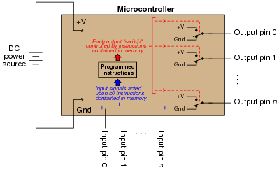
A microcontroller unit, or MCU, is a specialized type of digital computer used to provide automatic sequencing or control of a system. Microcontrollers differ from ordinary digital computers in being very small (typically a single integrated circuit chip), with several dedicated pins for input and/or output of digital signals, and limited memory. Instructions programmed into the microcontroller's memory tell it how to react to input conditions, and what types of signals to send to the outputs.
The simplest type of signal ünderstood" by a microcontroller is a discrete voltage level: either "high" (approximately +V) or "low" (approximately ground potential) measured at a specified pin on the chip. Transistors internal to the microcontroller produce these "high" and "low" signals at the output pins, their actions being modeled by SPDT switches for simplicity's sake:
|
|
Microcontrollers may be programmed to emulate the functions of digital logic gates (AND, OR, NAND, NOR, etc.) in addition to a wide variety of combinational and multivibrator functions. The only real limits to what a microcontroller can do are memory (how large of a program may be stored) and input/output pins on the MCU chip.
However, microcontrollers are themselves made up of many thousands (or millions!) of logic gate circuits. Why would it make sense to use a microcontroller to perform a logic function that a small fraction of its constituent gates could accomplish directly? In other words, why would anyone bother to program a microcontroller to perform a digital function when they could build the logic network they needed out of fewer gate circuits?
Notes:
Note that I did not bother to explain my extremely terse answer. This is a subject I desire students to think long and hard about, for the real answer(s) to this question are the reasons driving all development of programmable digital devices.
Question 3:
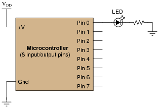
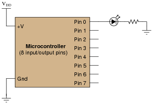
A student decides to build a light-flasher circuit using a microcontroller instead of a 555 timer or some other hard-wired astable circuit. Unfortunately, there is a problem somewhere. When first powered up, the LED lights on for 1 second, then turns off and never turns back on. The only way the LED ever comes back on is if the MCU is reset or its power is cycled off and on:
|
|
Pseudocode listing
Declare Pin0 as an output
BEGIN
Set Pin0 HIGH
Pause for 1 second
Set Pin0 LOW
END
A fellow student, when asked for help, modifies the program listing and re-sends it from the personal computer where it is being edited to the microcontroller, through a programming cable. The program listing now reads as such:
Pseudocode listing
Declare Pin0 as an output
LOOP
Set Pin0 HIGH
Pause for 1 second
Set Pin0 LOW
ENDLOOP
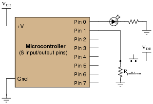
When the MCU is reset with the new program, the LED starts blinking on and off . . . sort of. The LED is ön" most of the time, but once every second it turns off and then immediately comes back on. In fact, the öff" period is so brief it is barely noticeable.
What the student wanted was a 50% duty cycle: ön" for 1 second, then öff" for 1 second, repeating that cycle indefinitely. First, explain the significance of the classmate's program modification, and then modify the program listing again so that the LED does what the student wants it to.
Pseudocode listing
Declare Pin0 as an output
LOOP
Set Pin0 HIGH
Pause for 1 second
Set Pin0 LOW
Pause for 1 second (new line of code)
ENDLOOP
Notes:
The purpose of this question is for students to realize that the microcontroller must be told to "loop" through the light blinking instructions. Really, this is just an illustration of loops in a practical context.
In case you're wondering why I write in pseudocode, here are a few reasons:
- �
- No prior experience with programming required to understand pseudocode
- �
- It never goes out of style
- �
- Hardware independent
- �
- No syntax errors
If I had decided to showcase code that would actually run in a microcontroller, I would be dooming the question to obsolescence. This way, I can communicate the spirit of the program without being chained to an actual programming standard. The only drawback is that students will have to translate my pseudocode to real code that will actually run on their particular MCU hardware, but that is a problem guaranteed for some regardless of which real programming language I would choose.
Of course, I could have taken the Donald Knuth approach and invented my own (imaginary) hardware and instruction set . . .
Question 4:
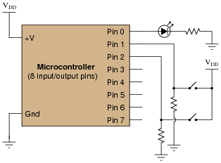
A student decides to build a light-flasher circuit using a microcontroller. The LED is supposed to blink on and off only when the pushbutton switch is depressed. It is supposed to turn off when the switch is released:
|
|
Pseudocode listing
Declare Pin0 as an output
Declare Pin1 as an input
WHILE Pin1 is HIGH
Set Pin0 HIGH
Pause for 0.5 seconds
Set Pin0 LOW
Pause for 0.5 seconds
ENDWHILE
The LED blinks on and off just fine as long as the pushbutton switch is held when the MCU is powered up or reset. As soon as the switch is released, the LED turns off and never comes back on. If the switch was never pressed during start-up, the LED never comes on! Explain what is happening, and modify the program as necessary to fix this problem.
Pseudocode listing
Declare Pin0 as an output
Declare Pin1 as an input
LOOP
WHILE Pin1 is HIGH
Set Pin0 HIGH
Pause for 0.5 seconds
Set Pin0 LOW
Pause for 0.5 seconds
ENDWHILE
ENDLOOP
Follow-up question: what purpose does the resistor Rpulldown serve in the pushbutton circuit?
Notes:
The purpose of this question is for students to understand what a "WHILE" loop represents in practical terms: a loop with condition(s). It also contrasts conditional looping against unconditional looping, and shows how both play a part in interactive systems such as this one.
In case you're wondering why I write in pseudocode, here are a few reasons:
- �
- No prior experience with programming required to understand pseudocode
- �
- It never goes out of style
- �
- Hardware independent
- �
- No syntax errors
If I had decided to showcase code that would actually run in a microcontroller, I would be dooming the question to obsolescence. This way, I can communicate the spirit of the program without being chained to an actual programming standard. The only drawback is that students will have to translate my pseudocode to real code that will actually run on their particular MCU hardware, but that is a problem guaranteed for some regardless of which real programming language I would choose.
Of course, I could have taken the Donald Knuth approach and invented my own (imaginary) hardware and instruction set . . .
Question 5:
Examine the following schematic diagram and program listing (written in "pseudocode" rather than a formal programming language) to determine what type of basic logic function is being implemented in this microcontroller unit:
|
|
Pseudocode listing
Declare Pin0 as an output
Declare Pin1 and Pin2 as inputs
LOOP
IF Pin1 is HIGH, set Pin0 HIGH
ELSEIF Pin2 is HIGH, set Pin0 HIGH
ELSE set Pin0 LOW
ENDIF
ENDLOOP
Notes:
Although this logic function could have been implemented easier and cheaper in hard-wired (gate) logic, the purpose is to get students to think of performing logical operations by a sequenced set of instructions inside a programmable device (the MCU). This is a conceptual leap, basic but very important.
In case you're wondering why I write in pseudocode, here are a few reasons:
- �
- No prior experience with programming required to understand pseudocode
- �
- It never goes out of style
- �
- Hardware independent
- �
- No syntax errors
If I had decided to showcase code that would actually run in a microcontroller, I would be dooming the question to obsolescence. This way, I can communicate the spirit of the program without being chained to an actual programming standard. The only drawback is that students will have to translate my pseudocode to real code that will actually run on their particular MCU hardware, but that is a problem guaranteed for some regardless of which real programming language I would choose.
Of course, I could have taken the Donald Knuth approach and invented my own (imaginary) hardware and instruction set . . .
Question 6:
Examine the following schematic diagram and program listing (written in "pseudocode" rather than a formal programming language) to determine what type of basic logic function is being implemented in this microcontroller unit:

|
|
Pseudocode listing
Declare Pin0 as an output
Declare Pin1 and Pin2 as inputs
LOOP
IF Pin1 is LOW, set Pin0 LOW
ELSEIF Pin2 is LOW, set Pin0 LOW
ELSE set Pin0 HIGH
ENDIF
ENDLOOP
Notes:
Although this logic function could have been implemented easier and cheaper in hard-wired (gate) logic, the purpose is to get students to think of performing logical operations by a sequenced set of instructions inside a programmable device (the MCU). This is a conceptual leap, basic but very important.
In case you're wondering why I write in pseudocode, here are a few reasons:
- �
- No prior experience with programming required to understand pseudocode
- �
- It never goes out of style
- �
- Hardware independent
- �
- No syntax errors
If I had decided to showcase code that would actually run in a microcontroller, I would be dooming the question to obsolescence. This way, I can communicate the spirit of the program without being chained to an actual programming standard. The only drawback is that students will have to translate my pseudocode to real code that will actually run on their particular MCU hardware, but that is a problem guaranteed for some regardless of which real programming language I would choose.
Of course, I could have taken the Donald Knuth approach and invented my own (imaginary) hardware and instruction set . . .
Question 7:
Examine the following schematic diagram and program listing (written in "pseudocode" rather than a formal programming language) to determine what type of basic logic function is being implemented in this microcontroller unit:

|
|
Pseudocode listing
Declare Pin0 as an output
Declare Pin1 and Pin2 as inputs
LOOP
IF Pin1 is LOW, set Pin0 HIGH
ELSEIF Pin2 is LOW, set Pin0 HIGH
ELSE set Pin0 LOW
ENDIF
ENDLOOP
Notes:
Although this logic function could have been implemented easier and cheaper in hard-wired (gate) logic, the purpose is to get students to think of performing logical operations by a sequenced set of instructions inside a programmable device (the MCU). This is a conceptual leap, basic but very important.
In case you're wondering why I write in pseudocode, here are a few reasons:
- �
- No prior experience with programming required to understand pseudocode
- �
- It never goes out of style
- �
- Hardware independent
- �
- No syntax errors
If I had decided to showcase code that would actually run in a microcontroller, I would be dooming the question to obsolescence. This way, I can communicate the spirit of the program without being chained to an actual programming standard. The only drawback is that students will have to translate my pseudocode to real code that will actually run on their particular MCU hardware, but that is a problem guaranteed for some regardless of which real programming language I would choose.
Of course, I could have taken the Donald Knuth approach and invented my own (imaginary) hardware and instruction set . . .
Question 8:
Examine the following schematic diagram and program listing (written in "pseudocode" rather than a formal programming language) to determine what type of basic logic function is being implemented in this microcontroller unit:

|
|
Pseudocode listing
Declare Pin0 as an output
Declare Pin1 and Pin2 as inputs
LOOP
IF Pin1 is HIGH, set Pin0 LOW
ELSEIF Pin2 is HIGH, set Pin0 LOW
ELSE set Pin0 HIGH
ENDIF
ENDLOOP
Notes:
Although this logic function could have been implemented easier and cheaper in hard-wired (gate) logic, the purpose is to get students to think of performing logical operations by a sequenced set of instructions inside a programmable device (the MCU). This is a conceptual leap, basic but very important.
In case you're wondering why I write in pseudocode, here are a few reasons:
- �
- No prior experience with programming required to understand pseudocode
- �
- It never goes out of style
- �
- Hardware independent
- �
- No syntax errors
If I had decided to showcase code that would actually run in a microcontroller, I would be dooming the question to obsolescence. This way, I can communicate the spirit of the program without being chained to an actual programming standard. The only drawback is that students will have to translate my pseudocode to real code that will actually run on their particular MCU hardware, but that is a problem guaranteed for some regardless of which real programming language I would choose.
Of course, I could have taken the Donald Knuth approach and invented my own (imaginary) hardware and instruction set . . .
Question 9:
Examine the following schematic diagram and program listing (written in "pseudocode" rather than a formal programming language) to determine what type of basic logic function is being implemented in this microcontroller unit:

|
|
Pseudocode listing
Declare Pin0 as an output
Declare Pin1 and Pin2 as inputs
LOOP
IF Pin1 is same as Pin2, set Pin0 LOW
ELSE set Pin0 HIGH
ENDIF
ENDLOOP
Notes:
Although this logic function could have been implemented easier and cheaper in hard-wired (gate) logic, the purpose is to get students to think of performing logical operations by a sequenced set of instructions inside a programmable device (the MCU). This is a conceptual leap, basic but very important.
In case you're wondering why I write in pseudocode, here are a few reasons:
- �
- No prior experience with programming required to understand pseudocode
- �
- It never goes out of style
- �
- Hardware independent
- �
- No syntax errors
If I had decided to showcase code that would actually run in a microcontroller, I would be dooming the question to obsolescence. This way, I can communicate the spirit of the program without being chained to an actual programming standard. The only drawback is that students will have to translate my pseudocode to real code that will actually run on their particular MCU hardware, but that is a problem guaranteed for some regardless of which real programming language I would choose.
Of course, I could have taken the Donald Knuth approach and invented my own (imaginary) hardware and instruction set . . .
Question 10:
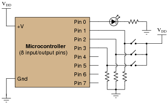
A microcontroller is a specialized type of digital computer used to provide automatic sequencing or control of a system. Microcontrollers differ from ordinary digital computers in being very small (typically a single integrated circuit chip), with several dedicated pins for input and/or output of digital signals, and limited memory. Instructions programmed into the microcontroller's memory tell it how to react to input conditions, and what types of signals to send to the outputs.
The simplest type of signal ünderstood" by a microcontroller is a discrete voltage level: either "high" (approximately +V) or "low" (approximately ground potential) measured at a specified pin on the chip. Transistors internal to the microcontroller produce these "high" and "low" signals at the output pins, their actions being modeled by SPDT switches for simplicity's sake:

|
|
It does not require much imagination to visualize how microcontrollers may be used in practical systems: turning external devices on and off according to input pin and/or time conditions. Examples include appliance control (oven timers, temperature controllers), automotive engine control (fuel injectors, ignition timing, self-diagnostic systems), and robotics (servo actuation, sensory processing, navigation logic). In fact, if you live in an industrialized nation, you probably own several dozen microcontrollers (embedded in various devices) and don't even realize it!
One of the practical limitations of microcontrollers, though, is their low output drive current limit: typically less than 50 mA. The miniaturization of the microcontroller's internal circuitry prohibits the inclusion of output transistors having any significant power rating, and so we must connect transistors to the output pins in order to drive any significant load(s).
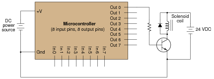
Suppose we wished to have a microcontroller drive a DC-actuated solenoid valve requiring 2 amps of current at 24 volts. A simple solution would be to use an NPN transistor as an ïnterposing" device between the microcontroller and the solenoid valve like this:
|
|
Unfortunately, a single BJT does not provide enough current gain to actuate the solenoid. With 20 mA of output current from the microcontroller pin and a b of only 25 (typical for a power transistor), this only provides about 500 mA to the solenoid coil.
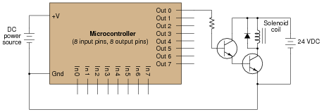
A solution to this problem involves two bipolar transistors in a Darlington pair arrangement:
|
|
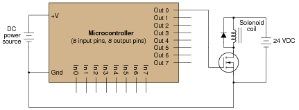
However, there is another solution yet - replace the single BJT with a single MOSFET, which requires no drive current at all. Show how this may be done:
|
|
|
|
Notes:
The purpose of this long-winded question is not just to have students figure out how to replace a BJT with a MOSFET, but also to introduce them to the concept of the microcontroller, which is a device of increasing importance in modern electronic systems.
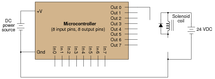
Some students may inquire as to the purpose of the diode in this circuit. Explain to them that this is a commutating diode, sometimes called a free-wheeling diode, necessary to prevent the transistor from being overstressed by high-voltage transients produced by the solenoid coil when de-energized (ïnductive kickback").
Question 11:
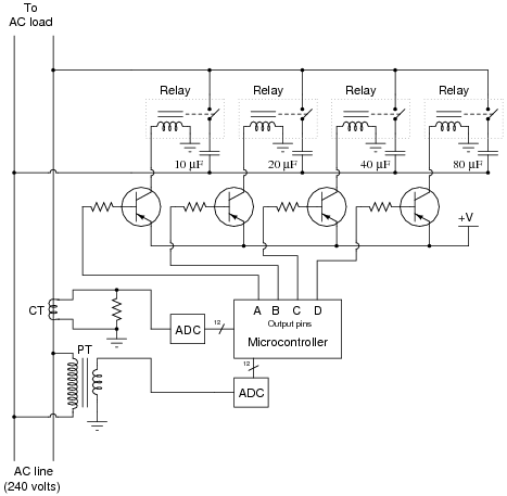
A microcontroller is used to provide automatic power factor correction for an AC load:
|
|
Examine this schematic diagram, then answer the following questions:
- �
- How can the microcontroller sense the power factor of the AC load?
- �
- How many discrete steps of power factor correction can the microcontroller engage through its four output pins?
- �
- What would the MCU's output be to correct for a load drawing 15 amps with a lagging power factor of 0.77? Assume a line frequency of 60 Hz, and a correction algorithm that adjusts for the best lagging power factor (i.e. it will never over-correct and produce a leading power factor).
- �
- What is the corrected (total) power factor with those capacitors engaged?
The 20 mF and 80 mF capacitors would both be engaged: MCU output DCBA would be 0101 (note that the outputs must go low to energize their respective relays!). With this output, the corrected power factor would be 0.99939 rather than the original 0.77.
Notes:
This question poses some interesting concepts for review, as well as synthesizing old and new concepts in electronics for your students to consider. Be sure to allow plenty of time for discussion on this question, as well as any necessary review time for power factor calculations!
Question 12:
This microcontroller is programmed to vary the perceived brightness of an LED by means of pulse-width modulation (PWM) control of pin 0's output:
|
|
Pseudocode listing
Declare Pin0 as an output
Declare X as an integer variable
LOOP
Set Pin0 LOW
Pause for 100 - X microseconds
Set Pin0 HIGH
Pause for X microseconds
ENDLOOP
Determine what the value of X must be to set the LED's brightness at 80%, and also what the frequency of the PWM signal is.
Follow-up question: what is the resolution of this PWM control, given that X is an integer variable? How might we improve the resolution of this PWM control scheme?
Notes:
Pulse-width modulation (PWM) is a very common and useful way of generating an analog output from a microcontroller (or other digital electronic circuit) capable only of "high" and "low" voltage level output. With PWM, time (or more specifically, duty cycle) is the analog domain, while amplitude is the digital domain. This allows us to ßneak" an analog signal through a digital (on-off) data channel.
In case you're wondering why I write in pseudocode, here are a few reasons:
- �
- No prior experience with programming required to understand pseudocode
- �
- It never goes out of style
- �
- Hardware independent
- �
- No syntax errors
If I had decided to showcase code that would actually run in a microcontroller, I would be dooming the question to obsolescence. This way, I can communicate the spirit of the program without being chained to an actual programming standard. The only drawback is that students will have to translate my pseudocode to real code that will actually run on their particular MCU hardware, but that is a problem guaranteed for some regardless of which real programming language I would choose.
Of course, I could have taken the Donald Knuth approach and invented my own (imaginary) hardware and instruction set . . .
Question 13:
Many microcontrollers come equipped with a built-in PWM function, so that you do not have to code a custom PWM algorithm yourself. This fact points to the popularity of pulse-width modulation as a control scheme. Explain why PWM is so popular, and give a few practical examples of how it may be used.
Notes:
Pulse-width modulation (PWM) is a very common and useful way of generating an analog output from a microcontroller (or other digital electronic circuit) capable only of "high" and "low" voltage level output. With PWM, time (or more specifically, duty cycle) is the analog domain, while amplitude is the digital domain. This allows us to ßneak" an analog signal through a digital (on-off) data channel.
Question 14:
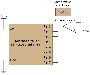
Pulse-width modulation (PWM) is not only useful for generating an analog output with a microcontroller, but it is also useful for receiving an analog input through a pin that only handles on-off (high-low) digital voltage levels. The following circuit takes an analog voltage signal in to a comparator, generates PWM, then sends that PWM signal to the input of a microcontroller:
|
|
Pseudocode listing
Declare Pin0 as an input
Declare Last_Pin0 as a boolean variable
Declare Time_High as an integer variable
Declare Time_Low as an integer variable
Declare Duty_Cycle as a floating-point variable
Set Time_High and Time_Low both to zero
LOOP
Set Last_Pin0 equal to Pin0
If Pin0 is HIGH, increment Time_High by one
If Pin0 is LOW, increment Time_Low by one
If Last_Pin0 is not equal to Pin0, go to SUBROUTINE
ENDLOOP
SUBROUTINE
Set Duty_Cycle equal to (Time_High / (Time_High + Time_Low))
Set Time_High and Time_Low both to zero
Return to calling loop
ENDSUBROUTINE
Explain how this program works. Hint: the Last_Pin0 boolean variable is used to detect when the state of Pin0 has changed from 0 to 1 or from 1 to 0.
Notes:
Pulse-width modulation (PWM) is a very common and useful way of generating an analog output from a microcontroller (or other digital electronic circuit) capable only of "high" and "low" voltage level output. Here, we also see it used as a form of input signal modulation. With PWM, time (or more specifically, duty cycle) is the analog domain, while amplitude is the digital domain. This allows us to ßneak" an analog signal through a digital (on-off) data channel.
In case you're wondering why I write in pseudocode, here are a few reasons:
- �
- No prior experience with programming required to understand pseudocode
- �
- It never goes out of style
- �
- Hardware independent
- �
- No syntax errors
If I had decided to showcase code that would actually run in a microcontroller, I would be dooming the question to obsolescence. This way, I can communicate the spirit of the program without being chained to an actual programming standard. The only drawback is that students will have to translate my pseudocode to real code that will actually run on their particular MCU hardware, but that is a problem guaranteed for some regardless of which real programming language I would choose.
Of course, I could have taken the Donald Knuth approach and invented my own (imaginary) hardware and instruction set . . .
Question 15:
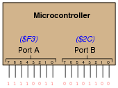
Digital computers communicate with external devices through ports: sets of terminals usually arranged in groups of 4, 8, 16, or more (4 bits = 1 nybble, 8 bits = 1 byte, 16 bits = 2 bytes). These terminals may be set to high or low logic states by writing a program for the computer that sends a numerical value to the port. For example, here is an illustration of a microcontroller being instructed to send the hexadecimal number F3 to port A and 2C to port B:
|
|
Suppose we wished to use the upper four bits of port A (pins 7, 6, 5, and 4) to drive the coils of a stepper motor in this eight-step sequence:
- Step 1:
- 0001
- Step 2:
- 0011
- Step 3:
- 0010
- Step 4:
- 0110
- Step 5:
- 0100
- Step 6:
- 1100
- Step 7:
- 1000
- Step 8:
- 1001
As each pin goes high, it drives a power MOSFET on, which sends current through that respective coil of the stepper motor. By following a ßhift" sequence as shown, the motor will rotate a small amount for each cycle.
Write the necessary sequence of numbers to be sent to port A to generate this specific order of bit shifts, in hexadecimal. Leave the lower four bit of port A all in the low logic state.
- Step 1:
- 1016
- Step 2:
- 3016
- Step 3:
- 2016
- Step 4:
- 6016
- Step 5:
- 4016
- Step 6:
- C016
- Step 7:
- 8016
- Step 8:
- 9016
Follow-up question: write the same sequence in decimal rather than hexadecimal:
- Step 1:
- Step 2:
- Step 3:
- Step 4:
- Step 5:
- Step 6:
- Step 7:
- Step 8:
Notes:
Although the root of this question is nothing more than binary-to-hexadecimal conversion, it also introduces students to the concept of controlling bit states in microcomputer ports by writing hex values. As such, this question is very practical!
In case students ask, let them know that a dollar sign prefix is sometimes used to denote a hexadecimal number. Other times, the prefix 0x is used (e.g., $F3 and 0xF3 mean the same thing).
Question 16:
Examine the following schematic diagram and program listing (written in "pseudocode" rather than a formal programming language) to determine what type of basic logic function is being implemented in this microcontroller unit:

|
|
Pseudocode listing
Declare Pin0 as an output
Declare Pin1 and Pin2 as inputs
LOOP
IF Pin1 is same as Pin2, set Pin0 HIGH
ELSE set Pin0 LOW
ENDIF
ENDLOOP
Notes:
Although this logic function could have been implemented easier and cheaper in hard-wired (gate) logic, the purpose is to get students to think of performing logical operations by a sequenced set of instructions inside a programmable device (the MCU). This is a conceptual leap, basic but very important.
In case you're wondering why I write in pseudocode, here are a few reasons:
- �
- No prior experience with programming required to understand pseudocode
- �
- It never goes out of style
- �
- Hardware independent
- �
- No syntax errors
If I had decided to showcase code that would actually run in a microcontroller, I would be dooming the question to obsolescence. This way, I can communicate the spirit of the program without being chained to an actual programming standard. The only drawback is that students will have to translate my pseudocode to real code that will actually run on their particular MCU hardware, but that is a problem guaranteed for some regardless of which real programming language I would choose.
Of course, I could have taken the Donald Knuth approach and invented my own (imaginary) hardware and instruction set . . .
Question 17:
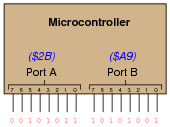
Digital computers communicate with external devices through ports: sets of terminals usually arranged in groups of 4, 8, 16, or more. These terminals may be set to high or low logic states by writing a program for the computer that sends a numerical value to the port. For example, here is an illustration of a microcontroller being instructed to send the hexadecimal number 2B to port A and A9 to port B:
|
|
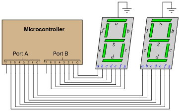
Suppose we wished to use the first seven bits of each port (pins 0 through 6) to drive two 7-segment, common-cathode displays, rather than use BCD-to-7-segment decoder ICs:
|
|
Write the necessary hexadecimal values to be output at ports A and B to generate the display "42" at the two 7-segment display units.
Note that the following answers are also valid:
Port A = DB16 Port B = E616
Follow-up question: write these same numerical values in decimal rather than hexadecimal.
Notes:
The root of this question is little more than binary-to-hexadecimal conversion, but it also introduces students to the concept of controlling bit states in microcomputer ports by writing hex values. As such, this question is very practical! Although it is unlikely that someone would omit BCD-to-7-segment decoders when building a two-digit decimal display (because doing it this way uses so many more precious microcontroller I/O pins), it is certainly possible! There are many applications other than this where you need to get the microcontroller to output a certain combination of high and low states, and the fastest way to program this is to output hex values to the ports.
In case students ask, let them know that a dollar sign prefix is sometimes used to denote a hexadecimal number. Other times, the prefix 0x is used (e.g., $F3 and 0xF3 mean the same thing).
Question 18:
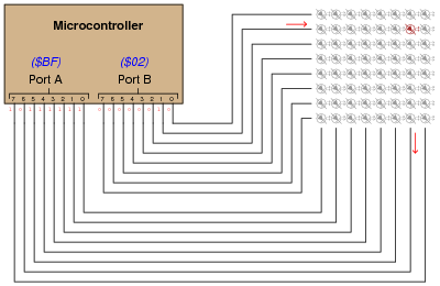
One method of driving pixels in a grid-based display is to organize the pixels into rows and columns, then select individual pixels for illumination by the intersection of a specific row line and a specific column line. In this example, we are controlling an 8 × 8 grid of LEDs with two 8-bit (1-byte) ports of a microcontroller:
|
|
Note that a high state is required on one of port B's pins to activate a row, and a low state is required on one of port A's pins to activate a column, because the LED anodes connect to port A and the LED cathodes connect to port B.
Determine the hexadecimal codes we would need to output at ports A and B to energize the LED in the far lower-left corner of the 8 × 8 grid.
Port A =
Port B =
Question 19:
Examine the following schematic diagram and program listing (written in "pseudocode" rather than a formal programming language) to determine what type of basic logic function is being implemented in this microcontroller unit:
|
|
Pseudocode listing
Declare Pin0 as an output
Declare Pin1, Pin2, and Pin3 as inputs
LOOP
IF Pin1 is HIGH, set Pin0 HIGH
ELSEIF Pin2 is HIGH, set Pin0 HIGH
ELSEIF Pin3 is HIGH, set Pin0 HIGH
ELSE set Pin0 LOW
ENDIF
ENDLOOP
Notes:
Although this logic function could have been implemented easier and cheaper in hard-wired (gate) logic, the purpose is to get students to think of performing logical operations by a sequenced set of instructions inside a programmable device (the MCU). This is a conceptual leap, basic but very important.
In case you're wondering why I write in pseudocode, here are a few reasons:
- �
- No prior experience with programming required to understand pseudocode
- �
- It never goes out of style
- �
- Hardware independent
- �
- No syntax errors
If I had decided to showcase code that would actually run in a microcontroller, I would be dooming the question to obsolescence. This way, I can communicate the spirit of the program without being chained to an actual programming standard. The only drawback is that students will have to translate my pseudocode to real code that will actually run on their particular MCU hardware, but that is a problem guaranteed for some regardless of which real programming language I would choose.
Of course, I could have taken the Donald Knuth approach and invented my own (imaginary) hardware and instruction set . . .
Question 20:
A student builds a microcontroller circuit to turn on an LED once for every five actuations of the input switch. The circuit is simple, with the microcontroller using a conditional loop to increment a variable each time the switch is pressed:

|
|
Pseudocode listing
Declare Pin0 as an output
Declare Pin1 as an input
Declare X as an integer variable
LOOP
WHILE Pin1 is HIGH
Add 1 to X (X=X+1)
ENDWHILE
IF X is equal to 5, set Pin0 HIGH and set X to 0
ELSE set Pin0 LOW
ENDIF
ENDLOOP
Unfortunately, the program does not execute as planned. Instead of the LED coming on once every five switch actuations, it seems to come on randomly when the switch is released. Sometimes the LED turns on after the first switch actuation, while other times it takes more than five pushes of the switch to get it to turn on.
After some careful analysis, it occurs to the student that the problem lies in the WHILE loop. As the microcontroller is much faster than the human hand, that loop executes many times while the switch is being pressed rather than only once, meaning that the variable X counts from 0 to 5 many times around for each switch actuation. It is only by chance, then, that X will be equal to five after the WHILE loop exits.
What the student needs is for the switch to increment by 1 only for an off-to-on switch transition: at the positive edge of the input pulse. The problem is how to do this using programming.
Another student, when faced with the same problem, chose to solve it this way and it worked just fine:
Pseudocode listing
Declare Pin0 as an output
Declare Pin1 as an input
Declare Switch as a Boolean (0 or 1) variable
Declare Last_Switch as a Boolean (0 or 1) variable
Declare X as an integer variable
LOOP
Set Last_Switch equal to Switch
Set Switch equal to Pin1
IF Switch = 1 and Last_Switch = 0 THEN add 1 to X (X=X+1)
ELSE do nothing to X
ENDIF
IF X is equal to 5, set Pin0 HIGH and set X to 0
ELSE set Pin0 LOW
ENDIF
ENDLOOP
Explain how this program successfully increments X only on each off-to-on transition of the pushbutton switch while the other program increments X rapidly during the entire duration the pushbutton switch is pressed.
Challenge question: does it matter where in the program the following two lines go? Must they be placed immediately prior to the IF/THEN conditional statement?
Set Last_Switch equal to Switch
Set Switch equal to Pin1
Notes:
This pulse-detection algorithm is very commonly used in programs dealing with real-world switch inputs. It performs in software what the pulse detection network does inside edge-triggered flip-flops, for the same effect: to initiate some kind of action only at the edge of a pulse signal.