Memory devices
Question 1:
| Don't just sit there! Build something!! |
Learning to analyze digital circuits requires much study and practice. Typically, students practice by working through lots of sample problems and checking their answers against those provided by the textbook or the instructor. While this is good, there is a much better way.
You will learn much more by actually building and analyzing real circuits, letting your test equipment provide the änswers" instead of a book or another person. For successful circuit-building exercises, follow these steps:
- 1.
- Draw the schematic diagram for the digital circuit to be analyzed.
- 2.
- Carefully build this circuit on a breadboard or other convenient medium.
- 3.
- Check the accuracy of the circuit's construction, following each wire to each connection point, and verifying these elements one-by-one on the diagram.
- 4.
- Analyze the circuit, determining all output logic states for given input conditions.
- 5.
- Carefully measure those logic states, to verify the accuracy of your analysis.
- 6.
- If there are any errors, carefully check your circuit's construction against the diagram, then carefully re-analyze the circuit and re-measure.
Always be sure that the power supply voltage levels are within specification for the logic circuits you plan to use. If TTL, the power supply must be a 5-volt regulated supply, adjusted to a value as close to 5.0 volts DC as possible.
One way you can save time and reduce the possibility of error is to begin with a very simple circuit and incrementally add components to increase its complexity after each analysis, rather than building a whole new circuit for each practice problem. Another time-saving technique is to re-use the same components in a variety of different circuit configurations. This way, you won't have to measure any component's value more than once.
Notes:
It has been my experience that students require much practice with circuit analysis to become proficient. To this end, instructors usually provide their students with lots of practice problems to work through, and provide answers for students to check their work against. While this approach makes students proficient in circuit theory, it fails to fully educate them.
Students don't just need mathematical practice. They also need real, hands-on practice building circuits and using test equipment. So, I suggest the following alternative approach: students should build their own "practice problems" with real components, and try to predict the various logic states. This way, the digital theory "comes alive," and students gain practical proficiency they wouldn't gain merely by solving Boolean equations or simplifying Karnaugh maps.
Another reason for following this method of practice is to teach students scientific method: the process of testing a hypothesis (in this case, logic state predictions) by performing a real experiment. Students will also develop real troubleshooting skills as they occasionally make circuit construction errors.
Spend a few moments of time with your class to review some of the "rules" for building circuits before they begin. Discuss these issues with your students in the same Socratic manner you would normally discuss the worksheet questions, rather than simply telling them what they should and should not do. I never cease to be amazed at how poorly students grasp instructions when presented in a typical lecture (instructor monologue) format!
I highly recommend CMOS logic circuitry for at-home experiments, where students may not have access to a 5-volt regulated power supply. Modern CMOS circuitry is far more rugged with regard to static discharge than the first CMOS circuits, so fears of students harming these devices by not having a "proper" laboratory set up at home are largely unfounded.
A note to those instructors who may complain about the "wasted" time required to have students build real circuits instead of just mathematically analyzing theoretical circuits:
What is the purpose of students taking your course?
If your students will be working with real circuits, then they should learn on real circuits whenever possible. If your goal is to educate theoretical physicists, then stick with abstract analysis, by all means! But most of us plan for our students to do something in the real world with the education we give them. The "wasted" time spent building real circuits will pay huge dividends when it comes time for them to apply their knowledge to practical problems.
Furthermore, having students build their own practice problems teaches them how to perform primary research, thus empowering them to continue their electrical/electronics education autonomously.
In most sciences, realistic experiments are much more difficult and expensive to set up than electrical circuits. Nuclear physics, biology, geology, and chemistry professors would just love to be able to have their students apply advanced mathematics to real experiments posing no safety hazard and costing less than a textbook. They can't, but you can. Exploit the convenience inherent to your science, and get those students of yours practicing their math on lots of real circuits!
Question 2:
When Digital Audio Tape (DAT) was first introduced to the American public, it was touted as delivering superior sound quality. Most importantly, this high quality of sound was not supposed to degrade over time like standard (analog) audio cassette tape recordings.
The magnetic media from which DAT was manufactured was basically the same stuff used to make analog audio tape. Explain why the encoding of audio data digitally on the same media would provide superior resistance to degradation over analog recordings even though the recording media was the same. Also, explain how this is significant to modern digital data storage technologies such as those used to store photographic images and numerical data.
Notes:
Challenge students to come up with some disadvantages of digital recordings, now that they understand the difference between analog and digital data storage. While digital technology certainly enjoys some advantages over analog, it is not necessarily superior in all aspects!
Question 3:
Define the following terms, as they relate to digital memory devices:
- �
- RAM:
- �
- ROM:
- �
- Volatile:
- �
- Nonvolatile:
In particular, explain why "RAM" is a misleading term.
Technically, RAM means Random-Access Memory, where data stored in memory may be accessed without having to ßift through" all the other bits of data in sequential order. In practice, however, the term RAM is used to designate the volatile electronic memory inside a computer, which just happens to be randomly accessible.
Notes:
The mis-use of the acronym "RAM" is another unfortunate entry in the lexicon of electronics. Your students are sure to have questions about this term, so be prepared to discuss it with them!
Question 4:
Determine whether the following recording devices are random access or sequential access, and discuss the advantage(s) of one type of access over the other:
- �
- DVD (disk)
- �
- Audio tape cassette
- �
- CD-ROM (disk)
- �
- ROM memory chip
- �
- Vinyl phonograph record
- �
- Video tape cassette
- �
- Magnetic "hard" drive
- �
- Magnetic bubble memory
- �
- Paper tape (a long strip of tape with holes punched in it)
- �
- RAM memory chip
- �
- DVD (disk) - random access
- �
- Audio tape cassette - sequential access
- �
- CD-ROM (disk) - random access
- �
- ROM memory chip - random access
- �
- Vinyl phonograph record - random access
- �
- Video tape cassette - sequential access
- �
- Magnetic "hard" drive - random access
- �
- Magnetic bubble memory - sequential access
- �
- Paper tape (a long strip of tape with holes punched in it) - sequential access
- �
- RAM memory chip - random access
Be prepared to discuss how each of these recording technologies works, and why each one is either random or sequential access.
Notes:
One of the purposes of this question is to get students to realize that "RAM" memory (solid-state, volatile memory "chips" in a computer) is not the only type of data storage device capable of randomly accessing its contents, and that the term "RAM" as it is commonly used is something of a misnomer.
Question 5:
Define the following acronyms:
- �
- ROM:
- �
- PROM:
- �
- EPROM:
- �
- EEPROM:
- �
- UVEPROM:
Be prepared to explain a few things about each of these memory technologies: how they work, what applications they might be found in, advantages and disadvantages of each.
- �
- ROM: Read-Only Memory
- �
- PROM: Programmable Read-Only Memory
- �
- EPROM: Erasable Programmable Read-Only Memory
- �
- EEPROM: Electrically Erasable Programmable Read-Only Memory
- �
- UVEPROM: UltraViolet Erasable Programmable Read-Only Memory
Notes:
ROM designations are another set of misnomers that have crept into the electronics lexicon. I mean really, how can anything be both erasable and programmable, but still be read-only?
Question 6:
Explain the difference between static RAM ("SRAM") and dynamic RAM ("DRAM") memory technologies. Which type of memory technology provides faster access of data, and why? Which type of memory technology provides the greatest storage density, and why?
Follow-up question: how is refreshing provided for dynamic RAM chips? Is this something taken care of internal to the chip, or must the circuit designer provide external circuitry to refresh the dynamic RAM chip's memory cells?
Notes:
Ask your students where they obtained their information on static versus dynamic RAM technologies. Extra credit for consulting datasheets!
Question 7:
Flash memory is a nonvolatile memory technology, offering greater density than either SRAM or DRAM, and faster erasure than standard EPROMs. At first, it would seem Flash memory outperforms all other memory types, but it doesn't. What are some of the disadvantages of Flash memory, and what kind of applications is it best suited for?
Notes:
Discuss with your students some of the different applications of Flash memory technology. Talk about how those applications fit the capabilities (and weaknesses) of Flash technology well.
Question 8:
Two very important concepts to understand when working with digital memory devices are address and data. Define each of these terms in your own words.
Notes:
Analogies are often helpful to communicate the concepts of äddress" and "data" to new students. I like to use the example of post office boxes (lots of addressed boxes, each containing different items) when I explain address and data.
Question 9:
A ROM memory chip is rated at 4k × 8 bits. What, exactly, does this designation mean? How many addresses are there inside this memory chip? How many bits of storage are there, total, in this memory chip? How many address bits are there, and how many data bits are there?
Notes:
Discuss with your students why there are not 4000 (exactly) addresses in a "4k" memory chip.
Question 10:
Suppose you need to store a text message in digital memory, consisting of 7500 ASCII characters. What is the most logical memory organization (addresses × data lines) to do this? How many address bits would be needed to store these 7500 characters?
Notes:
Be sure to ask your students how they calculated 13 bits for the address. Of course, there is the trial-and-error method of trying different powers of two, but there is a much more elegant solution involving logarithms to find the requisite number of bits.
Question 11:
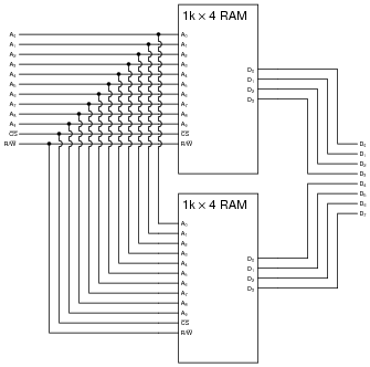
Suppose you need a memory array with 1k × 8 organization, but all you have on hand are 1k × 4 memory chips. Show how you could connect two of them to form the desired array:

|
|
|
|
Follow-up question: a common mistake made by students when they ëxpand" the data bus width of a memory array is to parallel the output lines (in the same way that the address lines are shown paralleled here). Why would this be wrong to do? What might happen to the memory chip(s) if their data lines were paralleled?
Notes:
Be sure to spend some time discussing the common mistake referenced in the follow-up question. This is something I've seen more than once, and it reveals a fundamental gap in understanding on the part of the mistaken student. What students are prone to do is try to memorize the sequence of connections rather than really understand why memory array expansion works, which leads to errors such as this.
Note that the answer to "what might happen" depends on whether the first operation is a read, or a write.
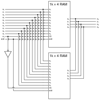
Question 12:
Suppose you need a memory array with 2k × 4 organization, but all you have on hand are 1k × 4 memory chips. Show how you could connect two of them to form the desired array:
|
|
|
|
Follow-up question: which of the two memory chips shown here stores the first 1024 addresses, and which one stores the next 1024 addresses? How can you tell?
Challenge question: as you can see, the expansion in addresses comes at the expense of losing the ability to simultaneously disable both memory chips. Add whatever logic gates are necessary to this circuit to provide a "global" [`CS] line for the 2k × 4 memory array.
Notes:
Be sure to spend some time discussing the follow-up question. Once again, I've noticed students are prone to memorizing the connection pattern rather than take the time to figure out why the chips are connected as they are.
Question 13:
Suppose you need a memory array with 4k × 4 organization, but all you have on hand are 1k × 4 memory chips. Explain how you could build a memory array of this size using multiple 1k × 4 chips.
Notes:
Although no schematic is given here in the answer, I expect my students to be able to draw one on their own.
Question 14:
Dynamic RAM chips often contain more addresses than they have address lines to select them with. For example, the MCM516100 DRAM chip has an organization of 16M × 1, yet it only has twelve address lines.
Explain how it is possible to select one out of 16 million unique addresses while using only twelve address lines. Hint: the technique is known as address multiplexing. Be sure to refer to one or more dynamic RAM datasheets when doing your research!
Follow-up question: explain how the memory chip "knows" which 12 bits of the address are being read at any given time.
Notes:
Explain to your students that address multiplexing is not technically limited to application in dynamic RAM chips only, but that it is usually applied there because of the high address density afforded by dynamic RAM technology. Most static RAMS, by contrast, are not dense enough to require address lines serve double-duty!
Question 15:
After a ROM memory has been programmed with data, it is good to verify that the data now stored is okay, and not corrupted with any errors. A popular method of doing this is to calculate a checksum on the stored data, and compare that against the checksum for the original data. If the checksum numbers are identical, chances are there are no corruptions in the stored data.
Explain exactly what checksum is, and how it works as an error-detection strategy.
Notes:
Once again, there is little I can reveal in the answer without giving everything away. There are enough resources available for students to learn about checksum on their own, that you should not have to supply additional information.
Question 16:
An important use for read-only semiconductor memories is as look-up tables. Describe what a "look-up table" is, and what one might be used for.
An example of a look-up table is an EBCDIC-to-ASCII code converter, where an EBCDIC code input to the address lines of a ROM chip "looks up" the equivalent ASCII character value from memory, and outputs it as the result through the ROM chip's data lines.
Notes:
The EBCDIC-to-ASCII code converter concept is not hypothetical! I actually designed and helped build such a circuit to allow standard personal computers to "talk" to an obsolete CNC machine tool control computer which didn't understand ASCII data, only EBCDIC. A look-up table implemented in a UVEPROM served as a neat way to implement this function, without a lot of complex circuitry.
Question 17:
Suppose an automobile manufacturer was designing a new car engine design, and they needed a memory chip to store look-up tables for the engine's control computer, holding data such as optimum fuel/air ratios for different engine loads which the computer would then consult to maintain best performance, or economy, or emissions. What type of memory chip would you recommend for the task, and why? Choose from the following list:
- �
- Static RAM (SRAM)
- �
- Mask ROM
- �
- PROM
- �
- Dynamic RAM (DRAM)
- �
- EPROM
- �
- Magnetic core
Notes:
This question is multi-faceted. Students must consider volatility and ease of updating (the data), as well as simply applying the concept of a look-up table to a car's engine control computer, in order to intelligently answer this question.
Question 18:
Research datasheets for the 74LS184 and 74LS185 integrated circuits, and then explain how read-only memory technology is used to perform the BCD/binary conversion functions.
Notes:
Discuss with your students why someone would choose to implement these functions in a look-up table instead of using combinational logic or a microprocessor/microcontroller. What advantage(s) might be realized with the look-up table approach?