Millman's theorem
Question 1:
| Don't just sit there! Build something!! |
Learning to mathematically analyze circuits requires much study and practice. Typically, students practice by working through lots of sample problems and checking their answers against those provided by the textbook or the instructor. While this is good, there is a much better way.
You will learn much more by actually building and analyzing real circuits, letting your test equipment provide the änswers" instead of a book or another person. For successful circuit-building exercises, follow these steps:
- 1.
- Carefully measure and record all component values prior to circuit construction.
- 2.
- Draw the schematic diagram for the circuit to be analyzed.
- 3.
- Carefully build this circuit on a breadboard or other convenient medium.
- 4.
- Check the accuracy of the circuit's construction, following each wire to each connection point, and verifying these elements one-by-one on the diagram.
- 5.
- Mathematically analyze the circuit, solving for all values of voltage, current, etc.
- 6.
- Carefully measure those quantities, to verify the accuracy of your analysis.
- 7.
- If there are any substantial errors (greater than a few percent), carefully check your circuit's construction against the diagram, then carefully re-calculate the values and re-measure.
Avoid very high and very low resistor values, to avoid measurement errors caused by meter "loading". I recommend resistors between 1 kW and 100 kW, unless, of course, the purpose of the circuit is to illustrate the effects of meter loading!
One way you can save time and reduce the possibility of error is to begin with a very simple circuit and incrementally add components to increase its complexity after each analysis, rather than building a whole new circuit for each practice problem. Another time-saving technique is to re-use the same components in a variety of different circuit configurations. This way, you won't have to measure any component's value more than once.
Notes:
It has been my experience that students require much practice with circuit analysis to become proficient. To this end, instructors usually provide their students with lots of practice problems to work through, and provide answers for students to check their work against. While this approach makes students proficient in circuit theory, it fails to fully educate them.
Students don't just need mathematical practice. They also need real, hands-on practice building circuits and using test equipment. So, I suggest the following alternative approach: students should build their own "practice problems" with real components, and try to mathematically predict the various voltage and current values. This way, the mathematical theory "comes alive," and students gain practical proficiency they wouldn't gain merely by solving equations.
Another reason for following this method of practice is to teach students scientific method: the process of testing a hypothesis (in this case, mathematical predictions) by performing a real experiment. Students will also develop real troubleshooting skills as they occasionally make circuit construction errors.
Spend a few moments of time with your class to review some of the "rules" for building circuits before they begin. Discuss these issues with your students in the same Socratic manner you would normally discuss the worksheet questions, rather than simply telling them what they should and should not do. I never cease to be amazed at how poorly students grasp instructions when presented in a typical lecture (instructor monologue) format!
A note to those instructors who may complain about the "wasted" time required to have students build real circuits instead of just mathematically analyzing theoretical circuits:
What is the purpose of students taking your course?
If your students will be working with real circuits, then they should learn on real circuits whenever possible. If your goal is to educate theoretical physicists, then stick with abstract analysis, by all means! But most of us plan for our students to do something in the real world with the education we give them. The "wasted" time spent building real circuits will pay huge dividends when it comes time for them to apply their knowledge to practical problems.
Furthermore, having students build their own practice problems teaches them how to perform primary research, thus empowering them to continue their electrical/electronics education autonomously.
In most sciences, realistic experiments are much more difficult and expensive to set up than electrical circuits. Nuclear physics, biology, geology, and chemistry professors would just love to be able to have their students apply advanced mathematics to real experiments posing no safety hazard and costing less than a textbook. They can't, but you can. Exploit the convenience inherent to your science, and get those students of yours practicing their math on lots of real circuits!
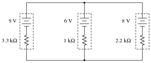
Question 2:
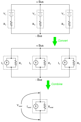
Convert all the "Thévenin" sources into Norton equivalent sources in this network:
|
|
|
|
Notes:
This is a good review of Thévenin / Norton power sources and their equivalencies.
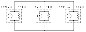
Question 3:
Simplify this circuit by combining all Norton sources into one, then solve for the voltage between the two busses:
|
|
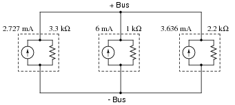
Question 4:
Write an algebraic equation that solves for the voltage between the two bus conductors, based on the problem-solving method of Thévenin-to-Norton conversion, combining Norton sources into one, and combining resistors into one:
|
|
|
Notes:
At first it may seem a bit overwhelming to derive an equation from these steps, but it is actually easier than it looks. A hint on how to do it: begin with the last step of the circuit simplification process, and work backwards as you elaborate your equation.
Question 5:
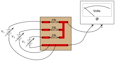
Calculate the voltage indicated by the voltmeter in this circuit for the following voltage inputs:
|
|
- V1 = 4.0 volts
- V2 = 5.0 volts
- V3 = 12.0 volts
What do you notice about the output voltage of this circuit? What mathematical function does this circuit perform?
This circuit is a very simple form of analog computer, because it has the ability to perform a mathematical operation, with voltages representing numerical quantities!
Notes:
Not only does this simple circuit provide an excellent opportunity to practice using Millman's theorem, but it also illustrates the important principle of using resistor networks to perform mathematical functions. In essence, this circuit is a form of computer (an analog computer), capable of "calculating" at a rate of speed unmatched by any digital computer.
Ask your students to think of the advantages an analog computer such as this would have over a digital computer, and visa-versa. How come analog computers are seldom used, and digital technology is so prevalent? Does this mean analog computer technology has no place in modern electronics?
Question 6:
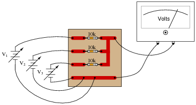
Suppose this circuit was found to output a voltage of 11.0 volts, given the input voltages shown:
|
|
- V1 = 8.5 volts
- V2 = 10.0 volts
- V3 = 12.0 volts
What do suspect is wrong with this circuit? How would you verify the cause of the incorrect output voltage?
Notes:
Note how even with a failed resistor, the circuit still performs the proper mathematical function (albeit, only regarding two of the input "channels" rather than three). Ask your students how they determined the source of the problem, and how they would verify that as being the fault, with just a single meter measurement.
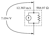
Question 7:
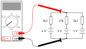
What would a digital voltmeter register, if connected to the circuit as shown below?
|
|
Notes:
A very common mistake I've seen students make is to disregard polarities when using Millman's theorem. If this appears to be a common problem in your class, ask your students if they think reversing one of the voltage source polarities would have any effect on the "bus" voltage. Of course, it should. Once students understand that polarity is significant, they can arrive at their own consistent approach to accounting for polarity in the Millman's theorem equation.
Another strategy for getting students to understand the significance of polarity when using Millman's theorem is to go back to the foundations of Millman's theorem: the principle of converting Thévenin sources into Norton sources. If a Thévenin source with a "backwards" battery is converted into a Norton source, that current source will subtract current from the rest of the current sources, leaving less to go through the total Norton resistance. Students should be able to readily understand the principle of Norton current sources adding versus subtracting, and this should then carry over into their use of the Millman's theorem equation.
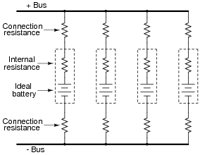
Question 8:
A set of batteries are connected in parallel to form a battery bank. Ideally, their individual voltages would be exactly equal, and there would be no stray resistance anywhere in the circuit, but in reality what we have is something like this:
|
|
Use Millman's theorem to calculate the total voltage between the two busses for the battery bank, given these specifications for the four batteries:
-
Battery Voltage Rconnection + Rconnection - Rinternal
1 11.9 1.2 W 1.1 W 5.5 W
2 12.2 1.0 W 1.3 W 5.1 W
3 12.0 1.4 W 0.9 W 4.7 W
4 12.1 1.1 W 1.2 W 5.5 W
Notes:
Millman's theorem is especially useful in making bus voltage calculations for power systems, where multiple sources (and loads!) are connected to the same two wires.
Question 9:
Calculate the voltage across the starter motor terminals of the "dead" car, and the current through the starter motor, while a second car is giving it a jump-start:

|
|
Regard the starter motor itself as a 0.15 W resistor, and disregard any resistance of the jumper cables connecting the two cars' electrical systems together.
Imotor = 63.56 A
Notes:
For a question like this, where an equivalent schematic diagram is essential to obtaining the solution, I recommend you have a student draw their equivalent schematic on the whiteboard in front of the class, and discuss the diagram with all your students before discussing how to apply Millman's theorem.
I have found it helpful for students to have them draw diagrams and mathematical solutions on a board in front of the rest of the class. Of course, you as the instructor must be careful to maintain a non-threatening environment in the classroom while students do this, as it tends to place a lot of stress on shy students. However, the ability to present graphical information to a group is a valuable skill, and exercises like this help to build it in your students.