Nonlinear opamp circuits
Question 1:
| Don't just sit there! Build something!! |
Learning to mathematically analyze circuits requires much study and practice. Typically, students practice by working through lots of sample problems and checking their answers against those provided by the textbook or the instructor. While this is good, there is a much better way.
You will learn much more by actually building and analyzing real circuits, letting your test equipment provide the änswers" instead of a book or another person. For successful circuit-building exercises, follow these steps:
- 1.
- Carefully measure and record all component values prior to circuit construction.
- 2.
- Draw the schematic diagram for the circuit to be analyzed.
- 3.
- Carefully build this circuit on a breadboard or other convenient medium.
- 4.
- Check the accuracy of the circuit's construction, following each wire to each connection point, and verifying these elements one-by-one on the diagram.
- 5.
- Mathematically analyze the circuit, solving for all voltage and current values.
- 6.
- Carefully measure all voltages and currents, to verify the accuracy of your analysis.
- 7.
- If there are any substantial errors (greater than a few percent), carefully check your circuit's construction against the diagram, then carefully re-calculate the values and re-measure.
Avoid using the model 741 op-amp, unless you want to challenge your circuit design skills. There are more versatile op-amp models commonly available for the beginner. I recommend the LM324 for DC and low-frequency AC circuits, and the TL082 for AC projects involving audio or higher frequencies.
As usual, avoid very high and very low resistor values, to avoid measurement errors caused by meter "loading". I recommend resistor values between 1 kW and 100 kW.
One way you can save time and reduce the possibility of error is to begin with a very simple circuit and incrementally add components to increase its complexity after each analysis, rather than building a whole new circuit for each practice problem. Another time-saving technique is to re-use the same components in a variety of different circuit configurations. This way, you won't have to measure any component's value more than once.
Notes:
It has been my experience that students require much practice with circuit analysis to become proficient. To this end, instructors usually provide their students with lots of practice problems to work through, and provide answers for students to check their work against. While this approach makes students proficient in circuit theory, it fails to fully educate them.
Students don't just need mathematical practice. They also need real, hands-on practice building circuits and using test equipment. So, I suggest the following alternative approach: students should build their own "practice problems" with real components, and try to mathematically predict the various voltage and current values. This way, the mathematical theory "comes alive," and students gain practical proficiency they wouldn't gain merely by solving equations.
Another reason for following this method of practice is to teach students scientific method: the process of testing a hypothesis (in this case, mathematical predictions) by performing a real experiment. Students will also develop real troubleshooting skills as they occasionally make circuit construction errors.
Spend a few moments of time with your class to review some of the "rules" for building circuits before they begin. Discuss these issues with your students in the same Socratic manner you would normally discuss the worksheet questions, rather than simply telling them what they should and should not do. I never cease to be amazed at how poorly students grasp instructions when presented in a typical lecture (instructor monologue) format!
A note to those instructors who may complain about the "wasted" time required to have students build real circuits instead of just mathematically analyzing theoretical circuits:
What is the purpose of students taking your course?
If your students will be working with real circuits, then they should learn on real circuits whenever possible. If your goal is to educate theoretical physicists, then stick with abstract analysis, by all means! But most of us plan for our students to do something in the real world with the education we give them. The "wasted" time spent building real circuits will pay huge dividends when it comes time for them to apply their knowledge to practical problems.
Furthermore, having students build their own practice problems teaches them how to perform primary research, thus empowering them to continue their electrical/electronics education autonomously.
In most sciences, realistic experiments are much more difficult and expensive to set up than electrical circuits. Nuclear physics, biology, geology, and chemistry professors would just love to be able to have their students apply advanced mathematics to real experiments posing no safety hazard and costing less than a textbook. They can't, but you can. Exploit the convenience inherent to your science, and get those students of yours practicing their math on lots of real circuits!
Question 2:
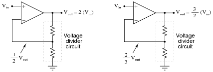
We know that an opamp connected to a voltage divider with a voltage division ratio of [1/2] will have an overall voltage gain of 2, and that the same circuit with a voltage division ratio of [2/3] will have an overall voltage gain of 1.5, or [3/2]:
|
|
There is definitely a mathematical pattern at work in these noninverting opamp circuits: the overall voltage gain of the circuit is the mathematical inverse of the feedback network's voltage gain.
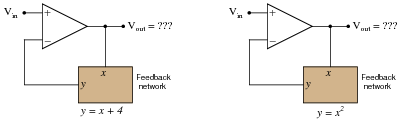
Building on this concept, what do you think would be the overall function of the following opamp circuits?
|
|
|
|
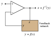
The result of placing a mathematical function in the feedback loop of a noninverting opamp circuit is that the output becomes the inverse function of the input: it literally becomes the value of x needed to solve for the input value of y:
|
|
Notes:
What is shown in this question and answer is a stark example of the power of negative feedback in a mathematical system. Here, we see the opamp's ability to solve for the input variable in an equation which we know the output value of. To state this in simpler terms, the opamp "does algebra" for us by "manipulating" the feedback network's equation to solve for x given an input signal of y.
Question 3:
The relationship between voltage and current for a PN junction is described by this equation, sometimes referred to as the "diode equation," or "Shockley's diode equation" after its discoverer:
|
Where,
ID = Current through the PN junction, in amps
IS = PN junction saturation current, in amps (typically 1 picoamp)
e = Euler's number � 2.718281828
q = Electron unit charge, 1.6 ×10⁻¹⁹ coulombs
VD = Voltage across the PN junction, in volts
N = Nonideality coefficient, or emission coefficient (typically between 1 and 2)
k = Boltzmann's constant, 1.38 ×10⁻²³
T = Junction temperature, degrees Kelvin
At first this equation may seem very daunting, until you realize that there are really only three variables in it: ID, VD, and T. All the other terms are constants. Since in most cases we assume temperature is fairly constant as well, we are really only dealing with two variables: diode current and diode voltage. Based on this realization, re-write the equation as a proportionality rather than an equality, showing how the two variables of diode current and voltage relate:
|
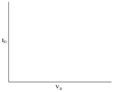
Based on this simplified equation, what would an I/V graph for a PN junction look like? How does this graph compare against the I/V graph for a resistor?
|
|
|
The graph described by the "diode formula" is a standard exponential curve, rising sharply as the independent variable (VD, in this case) increases. The corresponding graph for a resistor, of course, is linear.
Notes:
Ask your students to sketch their own renditions of an exponential curve on the whiteboard for all to see. Don't just let them get away with parroting the answer: Ït's an exponential curve."
Question 4:
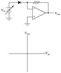
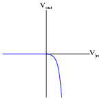
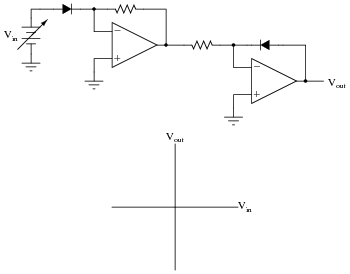
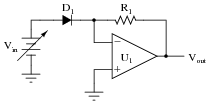
Plot the transfer function (Vout versus Vin) for this opamp circuit, and explain how the circuit works:
|
|
What type of mathematical function is represented by this circuit?
|
|
Notes:
The direction of the transfer function curve may surprise some students. Ask them why the curve goes down (negative) for increasingly positive input voltages.
Question 5:
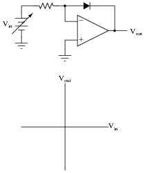
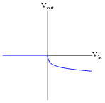
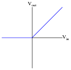
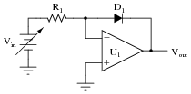
Plot the transfer function (Vout versus Vin) for this opamp circuit, and explain how the circuit works:
|
|
What type of mathematical function is represented by this circuit?
|
|
Notes:
The direction of the transfer function curve may surprise some students. Ask them why the curve goes down (negative) for increasingly positive input voltages.
Ask your students how they obtained this transfer function curve. There are conceptual methods for obtaining it, as well as algebraic methods. It would be interesting to compare more than one of these methods in a class discussion, and have students gain insight from each others' methods.
Question 6:
Plot the transfer function (Vout versus Vin) for this opamp circuit:
|
|
What type of mathematical function is represented by this circuit?
|
|
Notes:
It should be obvious from inspection that the two opamp circuits represent inverse mathematical functions. Ask your students why the final transfer function is linear rather than nonlinear. After all, they should realize that each of the opamp circuits, taken individually, are very nonlinear. Why would their combined effect be linear?
An interesting exercise would be to have your students perform inverse functions like this on their hand calculators, first calculating an exponential function (f(x) = ex), then a logarithmic (g(x) = lnx), and verifying the combined functions' output (f[g(x)] = x).
Question 7:
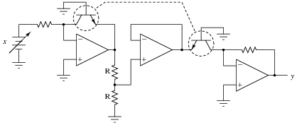
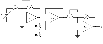
Identify the mathematical function of this circuit (if you look closely, you'll notice that the transistors are connected in such a way that they act very similar to diodes):
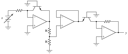
|
|
Note: the two resistors labeled "R" are equal in value.
Follow-up question: how could we modify this circuit so as to take the cube root of the input signal?
Notes:
This circuit is not nearly as complex as it may appear at first, if students take the time to isolate it section-by-section and identify the mathematical function each section performs.
Question 8:
Identify the mathematical function of this circuit (if you look closely, you'll notice that the transistors are connected in such a way that they act very similar to diodes):
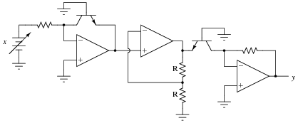
|
|
Note: the two resistors labeled "R" are equal in value.
Challenge question: why are transistors used instead of diodes, since they have been effectively "disabled" to act as such?
Notes:
This circuit is not nearly as complex as it may appear at first, if students take the time to isolate it section-by-section and identify the mathematical function each section performs.
Question 9:
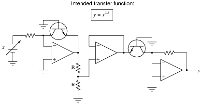
Suppose that in the course of building this exponential circuit you encounter severe inaccuracies: the circuit seems to work some of the time, but often its output deviates substantially (as much as +/- 10%) from what it ought to be:
|
|
Based on what you know of the components in this circuit, what could be varying so much as to cause these errors? What do you recommend as a solution to the problem?
|
|
Challenge question: is there a part we could order that contains two matched, heat-stabilized transistors for an application such as this? Are there any other circuit applications you can think of that could benefit from using a precision-matched pair of transistors?
Notes:
Ask your students to explain how they know temperature is an influencing factor in the accuracy of this circuit. Ask them to show any equations describing transistor behavior that demonstrate temperature dependence.
This question provides an opportunity to review the meaning of fractional exponents with your students. What, exactly, does y = x0.5 mean? Ask your students to write this expression using more common symbols. Also, ask them what would have to be modified in this circuit to alter the exponent's value.
As for the challenge question, ask your students to produce a part number for the precision-matched transistor pair they find. Where did they obtain the information on this component?
Question 10:
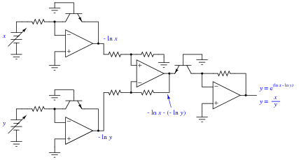
Design an op-amp circuit that divides one quantity (x) by another quantity (y) using logarithms. To give you a start on this circuit, I'll provide the initial logarithmic op-amp modules in this diagram:
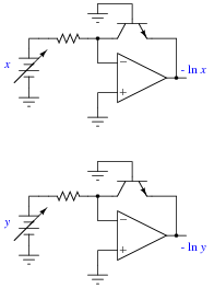
Note: it will be helpful for your analysis to write the mathematical expression at each op-amp output in your circuit, so you may readily see how the overall math function is constructed from individual steps.
|
|
Notes:
The circuit shown in the answer is a very common logarithmic construction: a log-ratio circuit, useful for many operations other than simple division. This question challenges students to put together the logarithm, antilogarithm, and differential op-amp circuits in a way that achieves the final design goal. Perhaps the most challenging aspect of this problem is managing the sign reversals.
Question 11:
Find a datasheet for the AD538, an integrated circuit manufactured by Analog Devices. Then, read it carefully and explain how it is able to perform arithmetic functions such as multiplication, division, powers, and roots.
Notes:
This question is destined for obsolescence, as one day the AD538 will no longer be manufactured. Until then, it is a fine piece of engineering, showcasing the power of logarithms as a computational aid in analog circuitry.
Question 12:
Predict how the operation of this exponentiator circuit will be affected as a result of the following faults. Consider each fault independently (i.e. one at a time, no multiple faults):
|
|
- �
- Resistor R1 fails open:
- �
- Solder bridge (short) across resistor R1:
- �
- Diode D1 fails open:
- �
- Diode D1 fails shorted:
For each of these conditions, explain why the resulting effects will occur.
- �
- Resistor R1 fails open: Vout saturates in the negative direction.
- �
- Solder bridge (short) across resistor R1: Vout goes to zero volts.
- �
- Diode D1 fails open: Vout goes to zero volts.
- �
- Diode D1 fails shorted: Vout saturates in the negative direction.
Notes:
The purpose of this question is to approach the domain of circuit troubleshooting from a perspective of knowing what the fault is, rather than only knowing what the symptoms are. Although this is not necessarily a realistic perspective, it helps students build the foundational knowledge necessary to diagnose a faulted circuit from empirical data. Questions such as this should be followed (eventually) by other questions asking students to identify likely faults based on measurements.
Question 13:
Predict how the operation of this logarithm extractor circuit will be affected as a result of the following faults. Consider each fault independently (i.e. one at a time, no multiple faults):
|
|
- �
- Resistor R1 fails open:
- �
- Solder bridge (short) across resistor R1:
- �
- Diode D1 fails open:
- �
- Diode D1 fails shorted:
For each of these conditions, explain why the resulting effects will occur.
- �
- Resistor R1 fails open: Vout goes to zero volts.
- �
- Solder bridge (short) across resistor R1: Vout saturates in the negative direction.
- �
- Diode D1 fails open: Vout saturates in the negative direction.
- �
- Diode D1 fails shorted: Vout goes to zero volts.
Notes:
The purpose of this question is to approach the domain of circuit troubleshooting from a perspective of knowing what the fault is, rather than only knowing what the symptoms are. Although this is not necessarily a realistic perspective, it helps students build the foundational knowledge necessary to diagnose a faulted circuit from empirical data. Questions such as this should be followed (eventually) by other questions asking students to identify likely faults based on measurements.
Question 14:
Explain why carefully matched resistors and transistors are necessary in log/antilog circuits, using your own words. Also, explain why the operational amplifiers themselves need not be matched as precisely as the discrete components.
Notes:
This question challenges students to identify the "weak points" of log/antilog circuits, explaining why certain component tolerances are critical and others are not. This is a good test of students' understanding regarding log/antilog circuits and their underlying theory.
Question 15:
This square root extraction circuit used to work fine, but then one day it stopped outputting the square root of the input signal, and instead simply reproduced the input signal with a gain of 1:
|
|
What could have gone wrong with this circuit to cause it to stop "calculating" the square root of the input? Be as detailed as possible in your answer.
Notes:
One must understand what is happening in this circuit and why in order to successfully diagnose the problem. Discuss this carefully with your students.
Question 16:
Identify at least two independent component faults which could cause this square root extraction circuit to always output 0 volts instead of the square root of input voltage x as it should:

|
|
Explain why each of your proposed faults would cause the output to stay at 0 volts.
Notes:
Students will likely identify opamp U3 as a potential fault, but this is really too easy. Encourage them to seek more interesting fault possibilities!
Question 17:
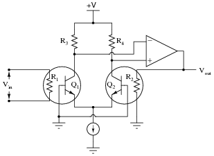
In the early 1970's, the Fluke company invented a revolutionary new "RMS sensor" integrated circuit, used to convert an arbitrary waveform into its DC-equivalent (RMS) voltage. The device uses two precision resistors to heat a pair of matched transistors connected as a differential pair:
|
|
Describe how this circuit functions. What physical principle(s) does it use to derive an RMS value for Vin? Why is it important that all identical components (transistors, resistors) be precisely matched?
Notes:
This question provides a good opportunity to review the function of differential pair circuits, and also the concept of RMS AC measurement. Ask your students how temperature influences the conductivity of bipolar junction transistors, and how the opamp's connection to resistor R2 forms a negative feedback loop.