Ohm's Law
Question 1:
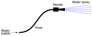
For a given amount of water pressure, which will flow a greater rate of water: a small (restrictive) nozzle or a large (unrestrictive) nozzle? Explain how this relates to the study of voltage, current, and resistance in a simple electric circuit.
|
|
Notes:
Water flow is not a perfect analogy for electricity, but is close enough to be useful in basic electricity education. Be prepared to discuss the inadequacies of water as an analogy with your students (i.e. "How come electrons don't spill out the end of an open wire like water spills out the end of an open hose or pipe?").
Question 2:
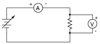
Suppose you were to build this circuit and take measurements of current through the resistor and voltage across the resistor:
|
|
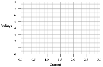
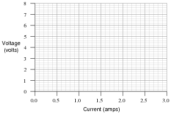
Recording these numerical values in a table, the results look something like this:
| XXXXXXX | XXXXXXX |
| Current | Voltage |
| 0.22 A | 0.66 V |
| 0.47 A | 1.42 V |
| 0.85 A | 2.54 V |
| 1.05 A | 3.16 V |
| 1.50 A | 4.51 V |
| 1.80 A | 5.41 V |
| 2.00 A | 5.99 V |
| 2.51 A | 7.49 V |
Plot these figures on the following graph:
|
|
What mathematical relationship do you see between voltage and current in this simple circuit?
Notes:
The raw data figures were made intentionally "noisy" in this problem to simulate the types of measurement errors encountered in real life. One tool which helps overcome interpretational problems resulting from noise like this is graphing. Even with noise present, the linearity of the function is quite clearly revealed.
Your students should learn to make graphs as tools for their own understanding of data. When relationships between numbers are represented in graphical form, it lends another mode of expression to the data, helping people to apprehend patterns easier than by reviewing rows and columns of numbers.
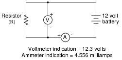
Question 3:
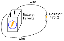
Explain, step by step, how to calculate the amount of current (I) that will go through the resistor in this circuit:
|
|
Notes:
Just a simple Ohm's Law calculation here - no tricks! The point of this question, however, is to get students to think about the steps they follow in doing the calculation. Many students simply wish to memorize procedures rather than learn why to do what they need to do to answer such questions. It is your task as the instructor to challenge them beyond memorization, and through to understanding.
Question 4:
|
Plot the relationships between voltage and current for resistors of three different values (1 W, 2 W, and 3 W), all on the same graph:
|
|
What pattern do you see represented by your three plots? What relationship is there between the amount of resistance and the nature of the voltage/current function as it appears on the graph?
Advanced question: in calculus, the instantaneous rate-of-change of an (x,y) function is expressed through the use of the derivative notation: [dy/dx]. How would the derivative for each of these three plots be properly expressed using calculus notation? Explain how the derivatives of these functions relate to real electrical quantities.
Advanced answer: the proper way to express the derivative of each of these plots is [dv/di]. The derivative of a linear function is a constant, and in each of these three cases that constant equals the resistor resistance in ohms. So, we could say that for simple resistor circuits, the instantaneous rate-of-change for a voltage/current function is the resistance of the circuit.
Notes:
Students need to become comfortable with graphs, and creating their own simple graphs is an excellent way to develop this understanding. A graphical representation of the Ohm's Law function allows students another "view" of the concept, allowing them to more easily understand more advanced concepts such as negative resistance.
If students have access to either a graphing calculator or computer software capable of drawing 2-dimensional graphs, encourage them to plot the functions using these technological resources.
I have found it a good habit to ßneak" mathematical concepts into physical science courses whenever possible. For so many people, math is an abstract and confusing subject, which may be understood only in the context of real-life application. The studies of electricity and electronics are rich in mathematical context, so exploit it whenever possible! Your students will greatly benefit.
Question 5:
What is the value of this resistor, in ohms (W)?
|
|
One format of component value expression popular in Europe is to replace the decimal point with the metric prefix, so 2.7 kW would be represented as 2k7 W. Not only is this notation simpler, but it also transcends the interpretational difficulties experienced between Europeans and Americans with their opposite usages of commas and decimal points.
Notes:
Some students might not realize that in Europe, commas are used as decimal points and visa-versa. Thus, two thousand seven hundred would be written as 2,700 in America and 2.700 in Europe. Conversely, the number p would be written as 3.141593 in America but 3,141593 in Europe. Confusing? Yes!!
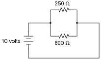
Question 6:
A common saying about electricity is that ït always takes the path of least resistance." Explain how this proverb relates to the following circuit, where electric current from the battery encounters two alternate paths, one being less resistive than the other:
|
|
Notes:
As an instructor, I was very surprised to hear many beginning students claim that all current would go through the lesser resistor, and none through the greater resistor! The proverb about "takes the path of least resistance" really should be understood as "proportionately taking paths of lesser resistance." People new to the study of electricity often misunderstand such basic principles, their errors usually based on folk wisdom like this. It is imperative to break through these myths with hard fact. In this case, Ohm's Law serves as a mathematical tool we can use to dispel false ideas.
Of course, a circuit as simple as this may be readily assembled and tested in class, so that all may see the truth for themselves.
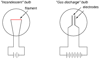
Question 7:
One style of light bulb, very different from the ïncandescent" design which works on the principle of a super-heated wire filament emitting light, is called a gas discharge tube. In this design of light bulb, light is produced by the direct ëxcitation" of gas molecules as electric current passes between two electrodes:
|
|
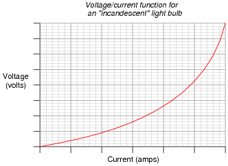
Both types of light bulbs have interesting voltage/current plots, neither one being identical to the voltage/current plot of a resistor. First, the voltage/current plot for an incandescent light bulb:
|
|
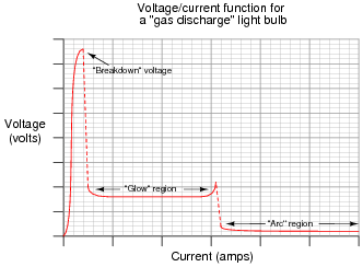
Next, the voltage/current plot for a gas-discharge light bulb:
|
|
Based on these two graphs, what can you say about the electrical resistance of each bulb type over its operating range?
From the graphs, determine where the resistance for each type of light bulb is at its maximum, and where the resistance is at its minimum.
Notes:
Many types of electrical and electronic components experience changes in electrical resistance over their operating ranges of current and voltage. Resistors, while simple to study, do not exhibit the behavior of most electronic components. It is important for students to understand that the real world of electricity and electronics is much more complex than what Ohm's Law might suggest (with an implicit assumption of fixed resistance). This is one concept that graphs really help to illustrate.
Question 8:
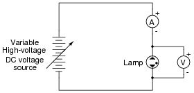
Draw the schematic diagram for an experimental circuit to gather data necessary to plot the voltage/current graph of a gas discharge lamp.
|
|
Notes:
One of my goals as a technical educator is to encourage the development of experimentation skills in my students. The most accurate way to gain knowledge of a device's operation or of an electrical principle is to build a circuit that actually tests it. I've used this technique many times in my career to further my knowledge on a subject, and it has proven to be an invaluable skill.
In this question, students are implicitly asked to identify several key things:
- �
- Where to connect a meter to measure lamp voltage.
- �
- Where to connect a meter to measure lamp current.
- �
- How to make the current adjustable, so that multiple values may be tested and plotted.
Question 9:
What is negative resistance?
Notes:
Not only do many gas-discharge devices exhibit negative resistance over certain portions of their operating range, but many semiconductor devices do as well.
Question 10:
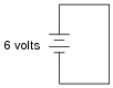
What would happen if a wire having no resistance at all (0 W) were connected directly across the terminals of a 6-volt battery? How much current would result, according to Ohm's Law?
|
|
Suppose we were to short-circuit a 6-volt battery in the manner just described and measure 8 amps of current. Why don't the calculated figures from the previous paragraph agree with the actual measurement?
If you think that the wire used in the experiment is not resistance-less (i.e. it does have resistance), and that this accounts for the disparity between the predicted and measured amounts of current, you are partially correct. Realistically, a small piece of wire such as that used in the experiment will have a few tenths of an ohm of resistance. However, if you re-calculate current with a wire resistance of 0.1 W, you will still find a large disparity between your prediction and the actual measured current in this short-circuit.
Follow-up question #1: explain why wire resistance alone does not explain the modest short-circuit current.
Follow-up question #2: identify at least one safety hazard associated with a real experiment such as this.
Notes:
Remind students that short-circuit testing of electrical power sources can be dangerous. A student of mine once stuffed a 6-volt "lantern" battery in his tool pouch, only to have it discharge smoke an hour later, after the battery terminals had been shorted together by a wrench handle!
No, Ohm's Law is not being cheated here: shorting a voltage source with a 0 W conductor will not result in infinite current, because there are other sources of resistance in such a circuit. The task here is to determine where those sources might be, and how they could be located.
Question 11:
Shunt resistors are often used as current-measuring devices, in that they are designed to drop very precise amounts of voltage as large electric currents pass through them. By measuring the amount of voltage dropped by a shunt resistor, you will be able to determine the amount of current going through it:
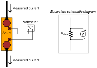
|
|
Suppose that a shunt resistance is labeled with the following rating: 150 A , 50 mV. What is the resistance of this shunt, in ohms? Express your answer in metric notation, scientific notation, and plain decimal notation.
Scientific notation: 3.333 ×10⁻⁴ W
Plain decimal notation: 0.0003333 W
Notes:
Ask your students how they think a resistor could be made with such a low resistance (a tiny fraction of an ohm!). What do they think a shunt resistor would look like in real life? If you happen to have a shunt resistor available in your classroom, show it to your students after they express their opinions on its construction.
Question 12:
| Don't just sit there! Build something!! |
Learning to mathematically analyze circuits requires much study and practice. Typically, students practice by working through lots of sample problems and checking their answers against those provided by the textbook or the instructor. While this is good, there is a much better way.
You will learn much more by actually building and analyzing real circuits, letting your test equipment provide the änswers" instead of a book or another person. For successful circuit-building exercises, follow these steps:
- 1.
- Carefully measure and record all component values prior to circuit construction.
- 2.
- Draw the schematic diagram for the circuit to be analyzed.
- 3.
- Carefully build this circuit on a breadboard or other convenient medium.
- 4.
- Check the accuracy of the circuit's construction, following each wire to each connection point, and verifying these elements one-by-one on the diagram.
- 5.
- Mathematically analyze the circuit, solving for all values of voltage, current, etc.
- 6.
- Carefully measure those quantities, to verify the accuracy of your analysis.
- 7.
- If there are any substantial errors (greater than a few percent), carefully check your circuit's construction against the diagram, then carefully re-calculate the values and re-measure.
Avoid very high and very low resistor values, to avoid measurement errors caused by meter "loading". I recommend resistors between 1 kW and 100 kW, unless, of course, the purpose of the circuit is to illustrate the effects of meter loading!
One way you can save time and reduce the possibility of error is to begin with a very simple circuit and incrementally add components to increase its complexity after each analysis, rather than building a whole new circuit for each practice problem. Another time-saving technique is to re-use the same components in a variety of different circuit configurations. This way, you won't have to measure any component's value more than once.
Notes:
It has been my experience that students require much practice with circuit analysis to become proficient. To this end, instructors usually provide their students with lots of practice problems to work through, and provide answers for students to check their work against. While this approach makes students proficient in circuit theory, it fails to fully educate them.
Students don't just need mathematical practice. They also need real, hands-on practice building circuits and using test equipment. So, I suggest the following alternative approach: students should build their own "practice problems" with real components, and try to mathematically predict the various voltage and current values. This way, the mathematical theory "comes alive," and students gain practical proficiency they wouldn't gain merely by solving equations.
Another reason for following this method of practice is to teach students scientific method: the process of testing a hypothesis (in this case, mathematical predictions) by performing a real experiment. Students will also develop real troubleshooting skills as they occasionally make circuit construction errors.
Spend a few moments of time with your class to review some of the "rules" for building circuits before they begin. Discuss these issues with your students in the same Socratic manner you would normally discuss the worksheet questions, rather than simply telling them what they should and should not do. I never cease to be amazed at how poorly students grasp instructions when presented in a typical lecture (instructor monologue) format!
A note to those instructors who may complain about the "wasted" time required to have students build real circuits instead of just mathematically analyzing theoretical circuits:
What is the purpose of students taking your course?
If your students will be working with real circuits, then they should learn on real circuits whenever possible. If your goal is to educate theoretical physicists, then stick with abstract analysis, by all means! But most of us plan for our students to do something in the real world with the education we give them. The "wasted" time spent building real circuits will pay huge dividends when it comes time for them to apply their knowledge to practical problems.
Furthermore, having students build their own practice problems teaches them how to perform primary research, thus empowering them to continue their electrical/electronics education autonomously.
In most sciences, realistic experiments are much more difficult and expensive to set up than electrical circuits. Nuclear physics, biology, geology, and chemistry professors would just love to be able to have their students apply advanced mathematics to real experiments posing no safety hazard and costing less than a textbook. They can't, but you can. Exploit the convenience inherent to your science, and get those students of yours practicing their math on lots of real circuits!
Question 13:
One of the fundamental equations used in electricity and electronics is Ohm's Law: the relationship between voltage (E or V, measured in units of volts), current (I, measured in units of amperes), and resistance (R, measured in units of ohms):
|
Where,
E = Voltage in units of volts (V)
I = Current in units of amps (A)
R = Resistance in units of ohms (W)
Solve for the unknown quantity (E, I, or R) given the other two, and express your answer in both scientific and metric notations:
I = 20 mA, R = 5 kW; E =
I = 150 mA, R = 47 kW; E =
E = 24 V, R = 3.3 MW; I =
E = 7.2 kV, R = 900 W; I =
E = 1.02 mV, I = 40 mA; R =
E = 3.5 GV, I = 0.76 kA; R =
I = 0.00035 A, R = 5350 W; E =
I = 1,710,000 A, R = 0.002 W; E =
E = 477 V, R = 0.00500 W; I =
E = 0.02 V, R = 992,000 W; I =
E = 150,000 V, I = 233 A; R =
E = 0.0000084 V, I = 0.011 A; R =
I = 150 mA, R = 47 kW; E = 7.1 V = 7.1 ×100 V
E = 24 V, R = 3.3 MW; I = 7.3 mA = 7.3 ×10⁻⁶ A
E = 7.2 kV, R = 900 W; I = 8.0 A = 8.0 ×100 A
E = 1.02 mV, I = 40 mA; R = 26 W = 2.6 ×101 W
E = 3.5 GV, I = 0.76 kA; R = 4.6 MW = 4.6 ×10⁶ W
I = 0.00035 A, R = 5350 W; E = 1.9 V = 1.9 ×100 V
I = 1,710,000 A, R = 0.002 W; E = 3.42 kV = 3.42 ×10³ V
E = 477 V, R = 0.00500 W; I = 95.4 kA = 9.54 ×10⁴ A
E = 0.02 V, R = 992,000 W; I = 20 nA = 2 ×10⁻⁸ A
E = 150,000 V, I = 233 A; R = 640 W = 6.4 ×10² W
E = 0.0000084 V, I = 0.011 A; R = 760 mW = 7.6 ×10⁻⁴ W
Notes:
In calculating the answers, I held to proper numbers of significant digits. This question is little more than drill for students learning how to express quantities in scientific and metric notations.
Question 14:
A quantity often useful in electric circuit analysis is conductance, defined as the reciprocal of resistance:
|
The unit of conductance is the siemens, symbolized by the capital letter "S". Convert the following resistance values into conductance values, expressing your answers in both scientific and metric notations:
R = 5 k W ; G =
R = 47 W ; G =
R = 500 M W ; G =
R = 18.2 mW ; G =
Now, algebraically manipulate the given equation to solve for R in terms of G, then use this new equation to work "backwards" through above calculations to see if you arrive at the original values of R starting with your previously calculated values of G.
R = 47 W ; G = 21 mS = 2.1 ×10⁻² S
R = 500 M W ; G = 2 nS = 2 ×10⁻⁹ S
R = 18.2 mW ; G = 55 kS = 5.5 ×10⁴ S
Solving for R in terms of G:
|
Notes:
Ask your students to show you exactly how they manipulated the equation to solve for R. The last instruction given in the question - working backwards through the five calculations to see if you get the original (given) figures in degrees Celsius - is actually a very useful way for students to check their algebraic work. Be sure to make note of this in class!
Question 15:
Suppose an electric current of 1.5 microamps (1.5 mA) were to go through a resistance of 2.3 mega-ohms (2.3 MW). How much voltage would be "dropped" across this resistance? Show your work in calculating the answer.
Notes:
It is important for students to understand that metric prefixes are nothing more than ßhorthand" forms of scientific notation, with each prefix corresponding to a specific power-of-ten.
Question 16:
One of the fundamental equations used in electricity and electronics is Ohm's Law: the relationship between voltage (E or V, measured in units of volts), current (I, measured in units of amperes), and resistance (R, measured in units of ohms):
|
Where,
E = Voltage in units of volts (V)
I = Current in units of amps (A)
R = Resistance in units of ohms (W)
Solve for the unknown quantity (E, I, or R) given the other two, and express your answer in both scientific and metric notations:
I = 45 mA, R = 3.0 kW; E =
I = 10 kA, R = 0.5 mW; E =
E = 45 V, R = 4.7 kW; I =
E = 13.8 kV, R = 8.1 kW; I =
E = 500 mV, I = 36 nA; R =
E = 14 V, I = 110 A; R =
I = 0.001 A, R = 922 W; E =
I = 825 A, R = 15.0 mW; E =
E = 1.2 kV, R = 30 MW; I =
E = 750 mV, R = 86 W; I =
E = 30.0 V, I = 0.0025 A; R =
E = 0.00071 V, I = 3389 A; R =
I = 10 kA, R = 0.5 mW; E = 5 V = 5 ×100 V
E = 45 V, R = 4.7 kW; I = 9.6 mA = 9.6 ×10⁻³ A
E = 13.8 kV, R = 8.1 kW; I = 1.7 A = 1.7 ×100 A
E = 500.0 mV, I = 36 nA; R = 14 kW = 1.4 ×10⁴ W
E = 14 V, I = 110 A; R = 130 mW = 1.3 ×10⁻¹ W
I = 0.001 A, R = 922 W; E = 900 mV = 9 ×10⁻¹ V
I = 825 A, R = 15.0 mW; E = 12.4 V = 1.24 ×101 V
E = 1.2 kV, R = 30 MW; I = 40 mA = 4 ×10⁻⁵ A
E = 750 mV, R = 86 W; I = 8.7 mA = 8.7 ×10⁻³ A
E = 30.0 V, I = 0.0025 A; R = 12 kW = 1.2 ×10⁴ W
E = 0.00071 V, I = 3389 A; R = 210 nW = 2.1 ×10⁻⁷ W
Notes:
In calculating the answers, I held to proper numbers of significant digits. This question is little more than drill for students learning how to express quantities in scientific and metric notations.