Opamp oscillator circuits
Question 1:
| Don't just sit there! Build something!! |
Learning to mathematically analyze circuits requires much study and practice. Typically, students practice by working through lots of sample problems and checking their answers against those provided by the textbook or the instructor. While this is good, there is a much better way.
You will learn much more by actually building and analyzing real circuits, letting your test equipment provide the änswers" instead of a book or another person. For successful circuit-building exercises, follow these steps:
- 1.
- Carefully measure and record all component values prior to circuit construction.
- 2.
- Draw the schematic diagram for the circuit to be analyzed.
- 3.
- Carefully build this circuit on a breadboard or other convenient medium.
- 4.
- Check the accuracy of the circuit's construction, following each wire to each connection point, and verifying these elements one-by-one on the diagram.
- 5.
- Mathematically analyze the circuit, solving for all voltage and current values.
- 6.
- Carefully measure all voltages and currents, to verify the accuracy of your analysis.
- 7.
- If there are any substantial errors (greater than a few percent), carefully check your circuit's construction against the diagram, then carefully re-calculate the values and re-measure.
Avoid using the model 741 op-amp, unless you want to challenge your circuit design skills. There are more versatile op-amp models commonly available for the beginner. I recommend the LM324 for DC and low-frequency AC circuits, and the TL082 for AC projects involving audio or higher frequencies.
As usual, avoid very high and very low resistor values, to avoid measurement errors caused by meter "loading". I recommend resistor values between 1 kW and 100 kW.
One way you can save time and reduce the possibility of error is to begin with a very simple circuit and incrementally add components to increase its complexity after each analysis, rather than building a whole new circuit for each practice problem. Another time-saving technique is to re-use the same components in a variety of different circuit configurations. This way, you won't have to measure any component's value more than once.
Notes:
It has been my experience that students require much practice with circuit analysis to become proficient. To this end, instructors usually provide their students with lots of practice problems to work through, and provide answers for students to check their work against. While this approach makes students proficient in circuit theory, it fails to fully educate them.
Students don't just need mathematical practice. They also need real, hands-on practice building circuits and using test equipment. So, I suggest the following alternative approach: students should build their own "practice problems" with real components, and try to mathematically predict the various voltage and current values. This way, the mathematical theory "comes alive," and students gain practical proficiency they wouldn't gain merely by solving equations.
Another reason for following this method of practice is to teach students scientific method: the process of testing a hypothesis (in this case, mathematical predictions) by performing a real experiment. Students will also develop real troubleshooting skills as they occasionally make circuit construction errors.
Spend a few moments of time with your class to review some of the "rules" for building circuits before they begin. Discuss these issues with your students in the same Socratic manner you would normally discuss the worksheet questions, rather than simply telling them what they should and should not do. I never cease to be amazed at how poorly students grasp instructions when presented in a typical lecture (instructor monologue) format!
A note to those instructors who may complain about the "wasted" time required to have students build real circuits instead of just mathematically analyzing theoretical circuits:
What is the purpose of students taking your course?
If your students will be working with real circuits, then they should learn on real circuits whenever possible. If your goal is to educate theoretical physicists, then stick with abstract analysis, by all means! But most of us plan for our students to do something in the real world with the education we give them. The "wasted" time spent building real circuits will pay huge dividends when it comes time for them to apply their knowledge to practical problems.
Furthermore, having students build their own practice problems teaches them how to perform primary research, thus empowering them to continue their electrical/electronics education autonomously.
In most sciences, realistic experiments are much more difficult and expensive to set up than electrical circuits. Nuclear physics, biology, geology, and chemistry professors would just love to be able to have their students apply advanced mathematics to real experiments posing no safety hazard and costing less than a textbook. They can't, but you can. Exploit the convenience inherent to your science, and get those students of yours practicing their math on lots of real circuits!
Question 2:
Explain what the Barkhausen criterion is for an oscillator circuit. How will the oscillator circuit's performance be affected if the Barkhausen criterion falls below 1, or goes much above 1?
Notes:
The question of "What is the Barkhausen criterion" could be answered with a short sentence, memorized verbatim from a textbook. But what I'm looking for here is real comprehension of the subject. Have your students explain to you the reason why oscillation amplitude depends on this factor.
Question 3:
How many degrees of phase shift must the feedback circuit (the square box in this schematic) introduce to the signal in order for this inverting amplifier circuit to oscillate?

|
|
Notes:
Ask your students to explain why the feedback network must provide 180 degrees of phase shift to the signal. Ask them to explain how this requirement relates to the need for regenerative feedback in an oscillator circuit.
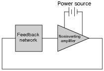
Question 4:
How many degrees of phase shift must the feedback circuit (the square box in this schematic) introduce to the signal in order for this noninverting amplifier circuit to oscillate?
|
|
Notes:
Ask your students to explain why the feedback network must provide 180 degrees of phase shift to the signal. Ask them to explain how this requirement relates to the need for regenerative feedback in an oscillator circuit.
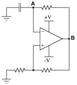
Question 5:
This is a very common opamp oscillator circuit, technically of the relaxation type:
|
|
Explain how this circuit works, and what waveforms will be measured at points A and B. Be sure to make reference to RC time constants in your explanation.
Challenge question: explain how you might go about calculating the frequency of such a circuit, based on what you know about RC time constant circuits. Assume that the opamp can swing its output rail-to-rail, for simplicity.
Notes:
This circuit is best understood by building and testing. If you use large capacitor values and/or a large-value resistor in the capacitor's current path, the oscillation will be slow enough to analyze with a voltmeter rather than an oscilloscope.
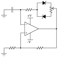
Question 6:
A variation on the common opamp relaxation oscillator design is this, which gives it variable duty cycle capability:
|
|
Explain how this circuit works, and which direction the potentiometer wiper must be moved to increase the duty cycle (more time spent with the opamp output saturated at +V and less time spent saturated at -V).
Notes:
This circuit is best understood by building and testing. If you use large capacitor values and/or a large-value resistor in the capacitor's current path, the oscillation will be slow enough to analyze with a voltmeter rather than an oscilloscope.
Incidentally, the Schottky diodes are not essential to this circuit's operation, unless the expected frequency is very high. Really, the purpose of the Schottky diodes, with their low forward voltage drops (0.4 volts typical) and minimal charge storage, is to make the opamp's job easier at every reversal of output polarity. Remember that this circuit is not exploiting negative feedback! Essentially, it is a positive feedback circuit, and every voltage drop and nonlinearity in the capacitor's current path will have an effect on capacitor charging/discharging.
Question 7:
Dual, or split, power supplies are very useful in opamp circuits because they allow the output voltage to rise above as well as sink below ground potential, for true AC operation. In some applications, though, it may not be practical or affordable to have a dual power supply to power your opamp circuit. In this event, you need to be able to figure out how to adapt your dual-supply circuit to single-supply operation.
A good example of such a challenge is the familiar opamp relaxation oscillator, shown here:
|
|
First, determine what would happen if we were to simply eliminate the negative portion of the dual power supply and try to run the circuit on a single supply (+V and Ground only):
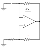
|
|
Then, modify the schematic so that the circuit will run as well as it did before with the dual supply.
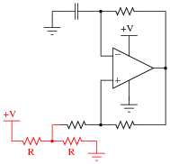
|
|
Here is another solution:
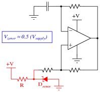
|
|
Follow-up question: now you just know what I'm going to ask next, don't you? How do these modified circuits function?
Notes:
Dual power supplies are a luxury in many real-life circumstances, and so your students will need to be able to figure out how to make opamps work in single-supply applications! Work with your students to analyze the function of the suggested solution circuit, to see how it is at once similar and different from its simpler, dual-supply forbear.
Question 8:
Identify what type of oscillator circuit this is, and write an equation describing its operating frequency:

|
|
|
Follow-up question: based on your analysis of the circuit, how much phase shift does the Wien bridge circuit introduce into the feedback signal?
Notes:
Unlike some discrete transistor oscillator circuits, this Wien bridge is a complete and full Wien bridge, and not a "half-bridge". For an example of a Wien half-bridge circuit, look at this (the Wien bridge components shown in a different color):
|
|
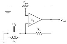
Question 9:
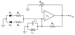
Explain the purpose of the tank circuit (L1 and C1) in the following oscillator circuit, and write an equation describing its operating frequency:

|
|
|
Follow-up question: what do you suppose the purpose of the potentiometer is in this oscillator circuit?
Notes:
Ask your students to describe the amount of phase shift the tank circuit provides to the feedback signal. Also, ask them to explain how the oscillator circuit's natural frequency may be altered.
Note: potentiometer (voltage gain) adjustment is crucial for obtaining a good-quality sine wave from this type of circuit. If your students decide to build one, they should be aware that some experimentation will be required to get it to output good-quality sine waves!
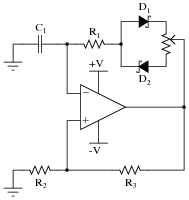
Question 10:
This Wien bridge oscillator circuit is very sensitive to changes in the gain. Note how the potentiometer used in this circuit is the "trimmer" variety, adjustable with a screwdriver rather than by a knob or other hand control:
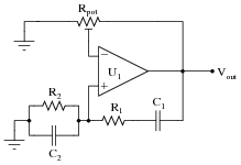
|
|
The reason for this choice in potentiometers is to make accidental changes in circuit gain less probable. If you build this circuit, you will see that tiny changes in this potentiometer's setting make a huge difference in the quality of the output sine wave. A little too much gain, and the sine wave becomes noticeably distorted. Too little gain, and the circuit stops oscillating altogether!
Obviously, it is not good to have such sensitivity to minor changes in any practical circuit expected to reliably perform day after day. One solution to this problem is to add a limiting network to the circuit comprised of two diodes and two resistors:
|
|
With this network in place, the circuit gain may be adjusted well above the threshold for oscillation (Barkhausen criterion) without exhibiting excessive distortion as it would have without the limiting network. Explain why the limiting network makes this possible.
Follow-up question: what effect does this "limiting network" have on the purity of the oscillator's output signal spectrum? In other words, does the limiting network increase or decrease the harmonic content of the output waveform?
Notes:
This circuit is important for students to encounter, as it reveals a very practical limitation of the "textbook" version of the Wien bridge oscillator circuit. It is not enough that a circuit design work in ideal conditions - a practical circuit must be able to tolerate some variance in component values or else it will not operate reliably.
Question 11:
This interesting opamp circuit produces true three-phase sinusoidal voltage waveforms, three of them to be exact:
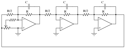
|
|
With all the resistors and capacitors, you might have guessed this to be a phase-shift type of oscillator circuit, and you would be correct. Here, each parallel RC network provides 60 degrees of lagging phase shift to combine with the 180 degrees of phase shift inherent to the inverting amplifier configurations, yielding 120 degrees of shift per opamp stage.
Derive a formula solving for the operating frequency of this oscillator circuit, knowing that the impedance of each parallel RC network will have a phase angle of -60o. Also, determine where on this circuit you would obtain the three promised sine waves.
|
I'll give you a hint on how to solve this problem: the admittance triangle for the parallel RC network will have angles of 60o, 30o, and of course 90o:
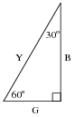
|
|
Notes:
Unlike the multi-stage RC phase shift networks we are accustomed to seeing in discrete transistor phase-shift oscillator circuits, the phase shift networks in this oscillator circuit are much "purer," being effectively isolated from each other by the current gain of each opamp. Here, each RC network provides the exact same amount of phase shift, and is not loaded by the RC network after it. This makes the math nice and easy (comparatively), and a good review of trigonometry!
This circuit came from the pages of one of my favorite opamp books, Applications Manual for Computing Amplifiers for Modeling, Measuring, Manipulation, and Much Else. Published by Philbrick Researches Inc. in 1966, it is a wonderfully written tour of "modern" operational amplifier applications and techniques. I only wish (truly) modern texts were written as well as this amazing booklet!
Question 12:
Predict how the operation of this relaxation oscillator circuit will be affected as a result of the following faults. Consider each fault independently (i.e. one at a time, no multiple faults):
|
|
- �
- Resistor R1 fails open:
- �
- Solder bridge (short) across resistor R1:
- �
- Capacitor C1 fails shorted:
- �
- Solder bridge (short) across resistor R2:
- �
- Resistor R3 fails open:
For each of these conditions, explain why the resulting effects will occur.
- �
- Resistor R1 fails open: Opamp output saturates either positive or negative.
- �
- Solder bridge (short) across resistor R1: Output voltage settles to 0 volts.
- �
- Capacitor C1 fails shorted: Opamp output saturates either positive or negative.
- �
- Solder bridge (short) across resistor R2: Output voltage settles to 0 volts.
- �
- Resistor R3 fails open: Output voltage settles to 0 volts.
Notes:
The purpose of this question is to approach the domain of circuit troubleshooting from a perspective of knowing what the fault is, rather than only knowing what the symptoms are. Although this is not necessarily a realistic perspective, it helps students build the foundational knowledge necessary to diagnose a faulted circuit from empirical data. Questions such as this should be followed (eventually) by other questions asking students to identify likely faults based on measurements.
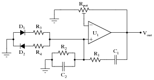
Question 13:
Identify at least two different component faults that would result in a change in duty cycle for this oscillator circuit:
|
|
Follow-up question: what would happen if either of these two diodes failed open?
Notes:
Ask your students to explain why the duty cycle would change as a result of either diode failing shorted. This is a good opportunity to further explore the operation of this oscillator circuit.
Question 14:
Suppose this LC oscillator stopped working, and you suspected either the capacitor or the inductor as having failed. How could you check these two components without the use of an LCR meter?
|
|
Follow-up question: is an ohmmeter test comprehensive enough to detect all possible faults with these two types of components? Why or why not? Be as specific as you can in your answer(s).
Notes:
Knowing how to check the condition of components with primitive test equipment is a valuable skill. It is well worth your time to discuss this question (and its answers) with your students in detail, so they all understand the concepts involved.
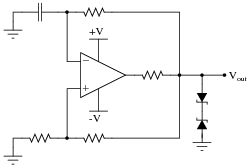
Question 15:
Most operational amplifiers do not have the ability to swing their output voltages rail-to-rail. Most of those do not swing their output voltages symmetrically. That is, a typical non-rail-to-rail opamp may be able to approach one power supply rail voltage closer than the other; e.g. when powered by a +15/-15 volt split supply, the output saturates positive at +14 volts and saturates negative at -13.5 volts.
What effect do you suppose this non-symmetrical output range will have on a typical relaxation oscillator circuit such as the following, and how might you suggest we fix the problem?
|
|
|
|
Follow-up question: explain how and why this solution works. Now you just knew I was going to ask this question the moment you saw the diagram, didn't you?
Notes:
Note that I added an additional resistor to the circuit, in series with the opamp output terminal. In some cases this is not necessary because the opamp is self-limiting in output current, but it is a good design practice nonetheless. In the event anyone ever swaps out the original opamp for a different model lacking overcurrent protection, the new opamp will not become damaged.
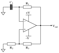
Question 16:
This resonant LC oscillator circuit is very sensitive to changes in the gain. Note how the potentiometer used in this circuit is the "trimmer" variety, adjustable with a screwdriver rather than by a knob or other hand control:

|
|
The reason for this choice in potentiometers is to make accidental changes in circuit gain less probable. If you build this circuit, you will see that tiny changes in this potentiometer's setting make a huge difference in the quality of the output sine wave. A little too much gain, and the sine wave becomes noticeably distorted. Too little gain, and the circuit stops oscillating altogether!
Obviously, it is not good to have such sensitivity to minor changes in any practical circuit expected to reliably perform day after day. One solution to this problem is to add a limiting network to the circuit comprised of two diodes and two resistors:
|
|
With this network in place, the circuit gain may be adjusted well above the threshold for oscillation (Barkhausen criterion) without exhibiting excessive distortion as it would have without the limiting network. Explain why the limiting network makes this possible.
Follow-up question: what effect does this "limiting network" have on the purity of the oscillator's output signal spectrum? In other words, does the limiting network increase or decrease the harmonic content of the output waveform?
Notes:
This circuit is important for students to encounter, as it reveals a very practical limitation of the "textbook" version of the resonant oscillator circuit. It is not enough that a circuit design work in ideal conditions - a practical circuit must be able to tolerate some variance in component values or else it will not operate reliably.