Open-loop opamp circuits
Question 1:
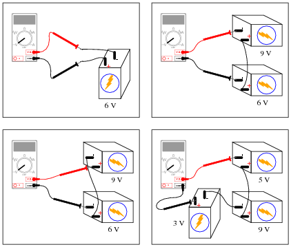
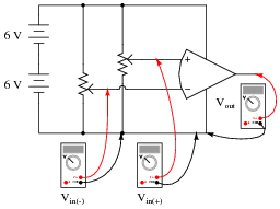
Determine what the magnitude and polarity of the voltmeter's indication will be in each case:
|
|

|
|
Notes:
Here, students must apply Kirchhoff's Voltage Law to determine what the voltmeter's indication will be. This question works well as a prelude to determining comparator (open-loop opamp) output polarities.
Question 2:
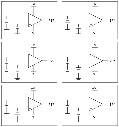
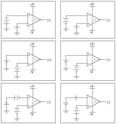
Determine the output voltage polarity of this op-amp (with reference to ground), given the following input conditions:
|
|
|
|
Notes:
Determining which "way" the output of an op-amp drives under different input voltage conditions is confusing to many students. Discuss this with them, and ask them to present any principles or analogies they use to remember "which way is which."
Question 3:
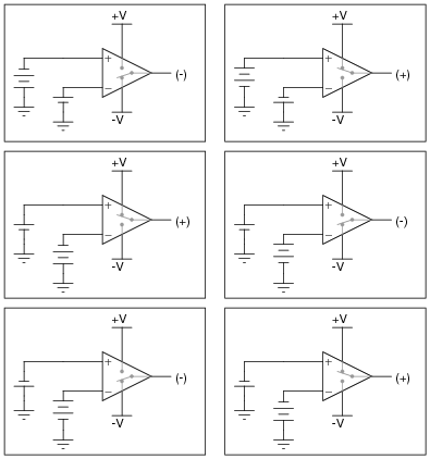
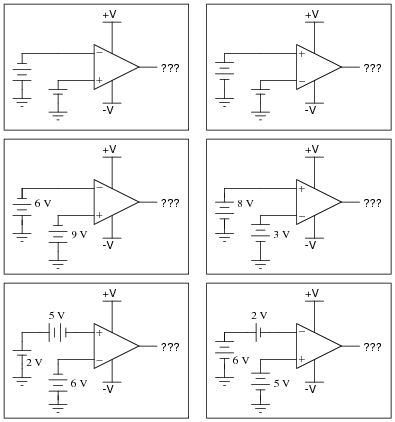
Determine the output voltage polarity of this op-amp (with reference to ground), given the following input conditions:
|
|
|
|
Notes:
Determining which "way" the output of an op-amp drives under different input voltage conditions is confusing to many students. Discuss this with them, and ask them to present any principles or analogies they use to remember "which way is which."
Question 4:
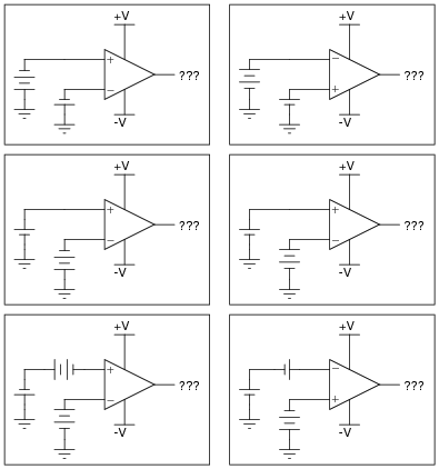
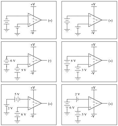
Determine the output voltage polarity of this op-amp (with reference to ground), given the following input conditions:
|
|
|
|
Notes:
Determining which "way" the output of an op-amp drives under different input voltage conditions is confusing to many students. Discuss this with them, and ask them to present any principles or analogies they use to remember "which way is which."
Question 5:
Although the following symbol is generally interpreted as an operational amplifier (öp-amp"), it may also be used to represent a comparator:

|
|
What is the difference between a comparator such as the model LM319, and a true operational amplifier such as the model LM324? Are the two devices interchangeable, or is there any significant difference despite the exact same schematic symbols? Explain your answer.
Notes:
The answer to this question invokes a couple of terms your students may not be familiar with yet: öpen-loop" and "feedback". Discuss these terms with your students, asking them first if they were able to arrive at definitions for them.
Question 6:
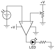
In this circuit, a solar cell converts light into voltage for the opamp to "read" on its noninverting input. The opamp's inverting input connects to the wiper of a potentiometer. Under what conditions does the LED energize?
|
|
Follow-up question: determine what would have to be changed in this circuit to make the LED turn on when the solar cell becomes dark.
Notes:
There is more than one way to accomplish the task posed by the follow-up question. Be sure to ask your students for their ideas on how to reverse the LED's operation!
Question 7:
What does the phrase open-loop voltage gain mean with reference to an operational amplifier? For a typical opamp, this gain figure is extremely high. Why is it important that the open-loop voltage gain be high when using an opamp as a comparator?
Notes:
The word ßaturation" is used often in electronics, especially in reference to amplifiers. Discuss the meaning and significance of this term with your students, especially in reference to comparator circuits, where the opamp is being used simply to compare to voltages and tell which one is greater.
Question 8:
A student is operating a simple comparator circuit and documenting the results in a table:
|
|
| MMMM | MMMM | MMMM | MMMM |
| Vin(+) | Vin(-) | Vout |
| 3.00 V | 1.45 V | 10.5 V |
| 3.00 V | 2.85 V | 10.4 V |
| 3.00 V | 3.10 V | 1.19 V |
| 3.00 V | 6.75 V | 1.20 V |
| Vin(+) | Vin(-) | Vout |
| 2.36 V | 6.50 V | 1.20 V |
| 4.97 V | 6.50 V | 1.21 V |
| 7.05 V | 6.50 V | 10.5 V |
| 9.28 V | 6.50 V | 10.4 V |
| Vin(+) | Vin(-) | Vout |
| 10.4 V | 9.87 V | 10.6 V |
| 1.75 V | 1.03 V | 10.5 V |
| 0.31 V | 1.03 V | 10.5 V |
| 5.50 | 5.65 V | 1.19 V |
One of these output voltage readings is anomalous. In other words, it does not appear to be "correct". This is very strange, because these figures are real measurements and not predictions! Perplexed, the student approaches the instructor and asks for help. The instructor sees the anomalous voltage reading and says two words: latch-up. With that, the student goes back to research what this phrase means, and what it has to do with the weird output voltage reading.
Identify which of these output voltage measurements is anomalous, and explain what "latch-up" has to do with it.
Challenge question: suppose we expected both input voltages to range between 0 and 10 volts during normal operation of this comparator circuit. What could we change in the circuit to allow this range of operation and avoid latch-up?
Notes:
Ask your students what they found in their research on "latch-up," and if this is an idiosyncrasy of all op-amp models, or just some.
Incidentally, the curved op-amp symbol has no special meaning. This symbol was quite popular for representing op-amps during their early years, but has since fallen out of favor. I show it here just to inform your students, in case they ever happen to encounter one of these symbols in an old electronic schematic.
Question 9:
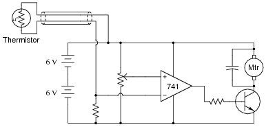
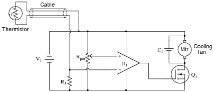
In this automatic cooling fan circuit, a comparator is used to turn a DC motor on and off when the sensed temperature reaches the ßetpoint" established by the potentiometer:
|
|
The circuit works just as it is supposed to in turning the motor on and off, but it has a strange problem: the transistor gets warm when the motor is off! Oddly enough, the transistor actually cools down when the motor turns on.
Describe what you would measure first in troubleshooting this problem. Based on the particular model of op-amp used (a model LM741C), what do you suspect is the problem here?
Challenge question: what purpose does the capacitor serve in this circuit? Hint: the capacitor is not required in a "perfect world," but it helps eliminate spurious problems in the real world!
Notes:
I've actually encountered this transistor heating problem in designing and building a very similar DC motor control circuit using the 741. There is a way to overcome this problem without switching to a different model of op-amp!
After discussing the nature of the problem with your students, you should talk about the virtues of getting a "low performance" op-amp such as the model 741 to work in a scenario like this rather than changing to an op-amp model capable of rail-to-rail operation. In my estimation, switching to a more modern op-amp in a circuit as simple as this is "cheating". There is nothing about this circuit that fundamentally taxes the capabilities of a 741 op-amp. All it takes is a little creativity to make it work properly.
Question 10:
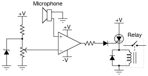
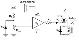
Explain the operation of this sound-activated relay circuit:
|
|
Follow-up question: how could we equip this circuit with the ability to turn the relay off once it has been turned on?
Notes:
There is a lot going on in this circuit that is not addressed in the answer I give. The basic purpose of the circuit should be fairly clear to understand, but the function of several components deserve further explanation. Ask your students to explain the functions of the diode on the comparator's output, the diode in parallel with the relay coil, the zener diode in parallel with the potentiometer, and the SCR.
Question 11:
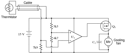
Calculate the amount of resistance that the thermistor much reach in order to turn the cooling fan on:
|
|
Notes:
Ask your students how they arrived at their solution for this question. There is definitely more than one way to do it!
Question 12:
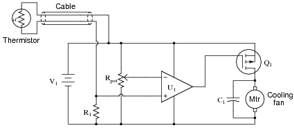
Predict how the operation of this thermostat circuit (where the cooling fan motor is supposed to turn on when the temperature gets too high) will be affected as a result of the following faults. Consider each fault independently (i.e. one at a time, no multiple faults):
|
|
- �
- Cable fails open:
- �
- Comparator U1 fails with output saturated positive:
- �
- Resistor R1 fails open:
- �
- Capacitor C1 fails shorted:
- �
- Transistor Q1 fails shorted (drain-to-source):
For each of these conditions, explain why the resulting effects will occur.
- �
- Cable fails open: Fan turns on and never turns off.
- �
- Comparator U1 fails with output saturated positive: Fan turns on and never turns off.
- �
- Resistor R1 fails open: Fan refuses to turn on.
- �
- Capacitor C1 fails shorted: Fan refuses to turn on, transistor Q1 likely fails due to overheating when it tries to energize fan.
- �
- Transistor Q1 fails shorted (drain-to-source): Fan turns on and never turns off.
Notes:
The purpose of this question is to approach the domain of circuit troubleshooting from a perspective of knowing what the fault is, rather than only knowing what the symptoms are. Although this is not necessarily a realistic perspective, it helps students build the foundational knowledge necessary to diagnose a faulted circuit from empirical data. Questions such as this should be followed (eventually) by other questions asking students to identify likely faults based on measurements.
Question 13:
Predict how the operation of this thermostat circuit (where the cooling fan motor is supposed to turn on when the temperature gets too high) will be affected as a result of the following faults. Consider each fault independently (i.e. one at a time, no multiple faults):
|
|
- �
- Cable fails open:
- �
- Comparator U1 fails with output saturated positive:
- �
- Resistor R1 fails open:
- �
- Cable fails shorted:
- �
- Transistor Q1 fails shorted (drain-to-source):
For each of these conditions, explain why the resulting effects will occur.
- �
- Cable fails open: Fan turns on and never turns off.
- �
- Comparator U1 fails with output saturated positive: Fan refuses to turn on.
- �
- Resistor R1 fails open: Fan refuses to turn on.
- �
- Cable fails shorted: Fan refuses to turn on.
- �
- Transistor Q1 fails shorted (drain-to-source): Fan turns on and never turns off.
Notes:
The purpose of this question is to approach the domain of circuit troubleshooting from a perspective of knowing what the fault is, rather than only knowing what the symptoms are. Although this is not necessarily a realistic perspective, it helps students build the foundational knowledge necessary to diagnose a faulted circuit from empirical data. Questions such as this should be followed (eventually) by other questions asking students to identify likely faults based on measurements.
Question 14:
Predict how the operation of this sound-activated relay circuit will be affected as a result of the following faults. Consider each fault independently (i.e. one at a time, no multiple faults):
|
|
- �
- Zener diode D1 fails open:
- �
- Resistor R1 fails open:
- �
- Resistor R2 fails open:
- �
- Microphone voice coil fails open:
- �
- Comparator U1 fails with output saturated positive:
- �
- Diode D3 fails shorted:
For each of these conditions, explain why the resulting effects will occur.
- �
- Zener diode D1 fails open: Volume threshold increases (relay may not energize at all).
- �
- Resistor R1 fails open: Any sound at all will energize the relay.
- �
- Resistor R2 fails open: Relay refuses to energize.
- �
- Microphone voice coil fails open: Relay energizes randomly, as comparator input is now sensitive to static electricity.
- �
- Comparator U1 fails with output saturated positive: Relay immediately energizes, whether or not there is sound.
- �
- Diode D3 fails shorted: Relay refuses to energize, SCR will likely be damaged due to overheating after a sound event.
Notes:
The purpose of this question is to approach the domain of circuit troubleshooting from a perspective of knowing what the fault is, rather than only knowing what the symptoms are. Although this is not necessarily a realistic perspective, it helps students build the foundational knowledge necessary to diagnose a faulted circuit from empirical data. Questions such as this should be followed (eventually) by other questions asking students to identify likely faults based on measurements.
Question 15:
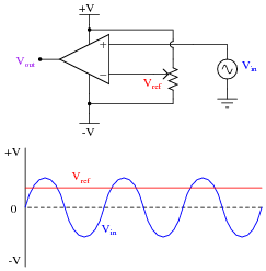
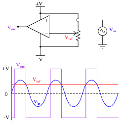
Trace the output waveform of this comparator circuit:
|
|
|
|
Follow-up question: explain what the phrase duty cycle means with reference to a ßquare" or "pulse" waveform.
Notes:
During discussion, ask your students to explain how the output waveform of this comparator circuit comes to be, step by step. Ask them how they arrived at their solution, and if there is a way this AC/DC problem can be simplified to one that is DC only for easier analysis (determining what the output voltage will do for a certain set of input conditions).
Question 16:
Explain what a window comparator circuit is (sometimes called a window discriminator), and identify at least one practical application for one.
Notes:
Ask your students where they found the answer for this question, and further explore some of the practical applications they offer.
Question 17:
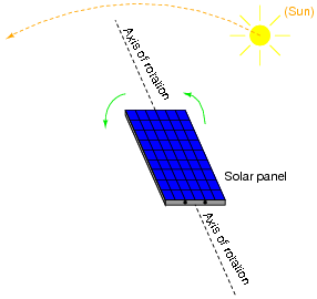
Photovoltaic solar panels produce the most output power when facing directly into sunlight. To maintain proper positioning, "tracker" systems may be used to orient the panels' direction as the sun "moves" from east to west across the sky:
|
|
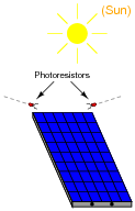
One way to detect the sun's position relative to the panel is to attach a pair of Light-Dependent Resistors (LDR's) to the solar panel in such a way that each LDR will receive an equal amount of light only if the panel is pointed directly at the sun:
|
|
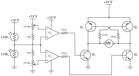
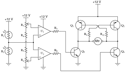
Two comparators are used to sense the differential resistance produced by these two LDR's, and activate a tracking motor to tilt the solar panel on its axis when the differential resistance becomes too great. An "H-drive" transistor switching circuit takes the comparators' output signals and amplifies them to drive a permanent-magnet DC motor one way or the other:
|
|
In this circuit, what guarantees that the two comparators never output a "high" (+V) voltage simultaneously, thus attempting to move the tracking motor clockwise and counter-clockwise at the same time?
Notes:
There is a lot going on in this comparator circuit for you and your students to discuss. Take time to talk about the operation of the entire circuit in detail, making sure students understand how every bit of it works.
If any of your students point out that there seem to be some power supply connections missing from the comparators (U1 and U2), discuss the fact that this notation is often used when multiple opamps or comparators are contained in the same integrated circuit. Often, the power supply connections will be omitted entirely for the sake of simplicity! Since everyone understands that opamps need DC power in order to function, the +V and -V (or ground) connections are simply assumed.
One misunderstanding I've seen with beginning students is to assume that signal input connections and power connections to an opamp are equivalent. That is, if an opamp does not receive +V/-V power through the normal power terminals, it will operate off of whatever voltages appear at its inverting and noninverting inputs. Nothing could be further from the truth! An ïnput" connection to a circuit denotes a signal to be detected, measured, or manipulated. A "power" connection is completely different. To use a stereo analogy, this is confusing the audio patch cable connections with the power cord.
Question 18:
Predict how the operation of this solar panel tracking circuit (where the tracking motor turns in response to a difference in light sensed by the two photoresistors) will be affected as a result of the following faults. Assuming that the motor spins clockwise when its left terminal is negative and its right terminal is positive (when Q2 and Q3 are both on), specify the direction of rotation (or non-rotation) resulting from each fault. Consider each fault independently (i.e. one at a time, no multiple faults):
|
|
- �
- Photoresistor R1 fails open:
- �
- Photoresistor R2 fails open:
- �
- Resistor R4 fails open:
- �
- Resistor R5 fails open:
- �
- Resistor R7 fails open:
- �
- Resistor R10 fails open:
- �
- Transistor Q3 fails open (collector-to-emitter):
For each of these conditions, explain why the resulting effects will occur.
- �
- Photoresistor R1 fails open: Motor continuously spins counter-clockwise.
- �
- Photoresistor R2 fails open: Motor continuously spins clockwise.
- �
- Resistor R4 fails open: Motor refuses to energize at all.
- �
- Resistor R5 fails open: Motor refuses to energize at all.
- �
- Resistor R7 fails open: Motor cannot spin clockwise, only counter-clockwise.
- �
- Resistor R10 fails open: Motor cannot spin counter-clockwise, only clockwise.
- �
- Transistor Q3 fails open (collector-to-emitter): Motor cannot spin clockwise, only counter-clockwise.
Notes:
The purpose of this question is to approach the domain of circuit troubleshooting from a perspective of knowing what the fault is, rather than only knowing what the symptoms are. Although this is not necessarily a realistic perspective, it helps students build the foundational knowledge necessary to diagnose a faulted circuit from empirical data. Questions such as this should be followed (eventually) by other questions asking students to identify likely faults based on measurements.
Question 19:
| Don't just sit there! Build something!! |
Learning to mathematically analyze circuits requires much study and practice. Typically, students practice by working through lots of sample problems and checking their answers against those provided by the textbook or the instructor. While this is good, there is a much better way.
You will learn much more by actually building and analyzing real circuits, letting your test equipment provide the änswers" instead of a book or another person. For successful circuit-building exercises, follow these steps:
- 1.
- Carefully measure and record all component values prior to circuit construction.
- 2.
- Draw the schematic diagram for the circuit to be analyzed.
- 3.
- Carefully build this circuit on a breadboard or other convenient medium.
- 4.
- Check the accuracy of the circuit's construction, following each wire to each connection point, and verifying these elements one-by-one on the diagram.
- 5.
- Mathematically analyze the circuit, solving for all voltage and current values.
- 6.
- Carefully measure all voltages and currents, to verify the accuracy of your analysis.
- 7.
- If there are any substantial errors (greater than a few percent), carefully check your circuit's construction against the diagram, then carefully re-calculate the values and re-measure.
Avoid using the model 741 op-amp, unless you want to challenge your circuit design skills. There are more versatile op-amp models commonly available for the beginner. I recommend the LM324 for DC and low-frequency AC circuits, and the TL082 for AC projects involving audio or higher frequencies.
As usual, avoid very high and very low resistor values, to avoid measurement errors caused by meter "loading". I recommend resistor values between 1 kW and 100 kW.
One way you can save time and reduce the possibility of error is to begin with a very simple circuit and incrementally add components to increase its complexity after each analysis, rather than building a whole new circuit for each practice problem. Another time-saving technique is to re-use the same components in a variety of different circuit configurations. This way, you won't have to measure any component's value more than once.
Notes:
It has been my experience that students require much practice with circuit analysis to become proficient. To this end, instructors usually provide their students with lots of practice problems to work through, and provide answers for students to check their work against. While this approach makes students proficient in circuit theory, it fails to fully educate them.
Students don't just need mathematical practice. They also need real, hands-on practice building circuits and using test equipment. So, I suggest the following alternative approach: students should build their own "practice problems" with real components, and try to mathematically predict the various voltage and current values. This way, the mathematical theory "comes alive," and students gain practical proficiency they wouldn't gain merely by solving equations.
Another reason for following this method of practice is to teach students scientific method: the process of testing a hypothesis (in this case, mathematical predictions) by performing a real experiment. Students will also develop real troubleshooting skills as they occasionally make circuit construction errors.
Spend a few moments of time with your class to review some of the "rules" for building circuits before they begin. Discuss these issues with your students in the same Socratic manner you would normally discuss the worksheet questions, rather than simply telling them what they should and should not do. I never cease to be amazed at how poorly students grasp instructions when presented in a typical lecture (instructor monologue) format!
A note to those instructors who may complain about the "wasted" time required to have students build real circuits instead of just mathematically analyzing theoretical circuits:
What is the purpose of students taking your course?
If your students will be working with real circuits, then they should learn on real circuits whenever possible. If your goal is to educate theoretical physicists, then stick with abstract analysis, by all means! But most of us plan for our students to do something in the real world with the education we give them. The "wasted" time spent building real circuits will pay huge dividends when it comes time for them to apply their knowledge to practical problems.
Furthermore, having students build their own practice problems teaches them how to perform primary research, thus empowering them to continue their electrical/electronics education autonomously.
In most sciences, realistic experiments are much more difficult and expensive to set up than electrical circuits. Nuclear physics, biology, geology, and chemistry professors would just love to be able to have their students apply advanced mathematics to real experiments posing no safety hazard and costing less than a textbook. They can't, but you can. Exploit the convenience inherent to your science, and get those students of yours practicing their math on lots of real circuits!