Inverting and noninverting opamp voltage amplifier circuits
Question 1:
| Don't just sit there! Build something!! |
Learning to mathematically analyze circuits requires much study and practice. Typically, students practice by working through lots of sample problems and checking their answers against those provided by the textbook or the instructor. While this is good, there is a much better way.
You will learn much more by actually building and analyzing real circuits, letting your test equipment provide the änswers" instead of a book or another person. For successful circuit-building exercises, follow these steps:
- 1.
- Carefully measure and record all component values prior to circuit construction.
- 2.
- Draw the schematic diagram for the circuit to be analyzed.
- 3.
- Carefully build this circuit on a breadboard or other convenient medium.
- 4.
- Check the accuracy of the circuit's construction, following each wire to each connection point, and verifying these elements one-by-one on the diagram.
- 5.
- Mathematically analyze the circuit, solving for all voltage and current values.
- 6.
- Carefully measure all voltages and currents, to verify the accuracy of your analysis.
- 7.
- If there are any substantial errors (greater than a few percent), carefully check your circuit's construction against the diagram, then carefully re-calculate the values and re-measure.
Avoid using the model 741 op-amp, unless you want to challenge your circuit design skills. There are more versatile op-amp models commonly available for the beginner. I recommend the LM324 for DC and low-frequency AC circuits, and the TL082 for AC projects involving audio or higher frequencies.
As usual, avoid very high and very low resistor values, to avoid measurement errors caused by meter "loading". I recommend resistor values between 1 kW and 100 kW.
One way you can save time and reduce the possibility of error is to begin with a very simple circuit and incrementally add components to increase its complexity after each analysis, rather than building a whole new circuit for each practice problem. Another time-saving technique is to re-use the same components in a variety of different circuit configurations. This way, you won't have to measure any component's value more than once.
Notes:
It has been my experience that students require much practice with circuit analysis to become proficient. To this end, instructors usually provide their students with lots of practice problems to work through, and provide answers for students to check their work against. While this approach makes students proficient in circuit theory, it fails to fully educate them.
Students don't just need mathematical practice. They also need real, hands-on practice building circuits and using test equipment. So, I suggest the following alternative approach: students should build their own "practice problems" with real components, and try to mathematically predict the various voltage and current values. This way, the mathematical theory "comes alive," and students gain practical proficiency they wouldn't gain merely by solving equations.
Another reason for following this method of practice is to teach students scientific method: the process of testing a hypothesis (in this case, mathematical predictions) by performing a real experiment. Students will also develop real troubleshooting skills as they occasionally make circuit construction errors.
Spend a few moments of time with your class to review some of the "rules" for building circuits before they begin. Discuss these issues with your students in the same Socratic manner you would normally discuss the worksheet questions, rather than simply telling them what they should and should not do. I never cease to be amazed at how poorly students grasp instructions when presented in a typical lecture (instructor monologue) format!
A note to those instructors who may complain about the "wasted" time required to have students build real circuits instead of just mathematically analyzing theoretical circuits:
What is the purpose of students taking your course?
If your students will be working with real circuits, then they should learn on real circuits whenever possible. If your goal is to educate theoretical physicists, then stick with abstract analysis, by all means! But most of us plan for our students to do something in the real world with the education we give them. The "wasted" time spent building real circuits will pay huge dividends when it comes time for them to apply their knowledge to practical problems.
Furthermore, having students build their own practice problems teaches them how to perform primary research, thus empowering them to continue their electrical/electronics education autonomously.
In most sciences, realistic experiments are much more difficult and expensive to set up than electrical circuits. Nuclear physics, biology, geology, and chemistry professors would just love to be able to have their students apply advanced mathematics to real experiments posing no safety hazard and costing less than a textbook. They can't, but you can. Exploit the convenience inherent to your science, and get those students of yours practicing their math on lots of real circuits!
Question 2:
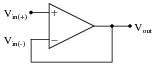
Write the transfer function (input/output equation) for an operational amplifier with an open-loop voltage gain of 100,000, and the inverting input connected directly to its output terminal. In other words, write an equation describing the output voltage of this op-amp (Vout) for any given input voltage at the noninverting input (Vin(+)):
|
|
Then, once you have an equation written, solve for the over-all voltage gain (AV = [(Vout)/(Vin(+))]) of this amplifier circuit, and calculate the output voltage for a noninverting input voltage of +6 volts.
|
(I've left it up to you to perform the algebraic simplification here!)
|
For an input voltage of +6 volts, the output voltage will be +5.99994 volts.
Notes:
The significant point of this question is that students see the over-all voltage gain of the opamp radically attenuated from 100,000 to approximately 1. What is not so evident is just how stable this new voltage gain is, which is one of the purposes for employing negative feedback.
Question 3:
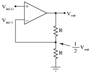
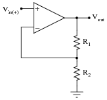
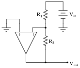
Write the transfer function (input/output equation) for an operational amplifier with an open-loop voltage gain of 100,000, and the inverting input connected to a voltage divider on its output terminal (so the inverting input receives exactly one-half the output voltage). In other words, write an equation describing the output voltage of this op-amp (Vout) for any given input voltage at the noninverting input (Vin(+)):
|
|
Then, once you have an equation written, solve for the output voltage if the noninverting input voltage is -2.4 volts.
(I've left it up to you to perform the algebraic simplification here!)
For an input voltage of -2.4 volts, the output voltage will be -4.7999 volts.
Follow-up question: what do you notice about the output voltage in this circuit? What value is it very close to being, in relation to the input voltage? Does this pattern hold true for other input voltages as well?
Notes:
Your students should see a definite pattern here as they calculate the output voltage for several different input voltage levels. Discuss this phenomenon with your students, asking them to explain it as best they can.
Question 4:
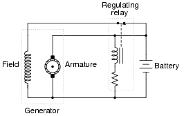
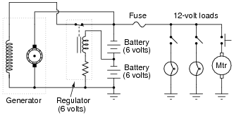
Generators used in battery-charging systems must be regulated so as to not overcharge the battery(ies) they are connected to. Here is a crude, relay-based voltage regulator for a DC generator:
|
|
Simple electromechanical relay circuits such as this one were very common in automotive electrical systems during the 1950's, 1960's, and 1970's. The fundamental principle upon which their operation is based is called negative feedback: where a system takes action to oppose any change in a certain variable. In this case, the variable is generator output voltage. Explain how the relay works to prevent the generator from overcharging the battery with excessive voltage.
Challenge question: what would we have to change in this circuit to alter the generator's voltage regulation set-point (the "target" voltage at which the generator's output is supposed to be regulated)?
Notes:
The circuit drawn here is very similar to real generator regulator circuits used in American automobiles before the advent of inexpensive, reliable semiconductor circuits. I show it here not just for historical background, but also to demonstrate how relatively crude circuits are still able to perform certain tasks reasonably well.
"Negative feedback" is one of the fundamental principles of electronics and electrical engineering. A simple system like this provides a good way to gently introduce students to this vital concept.
Question 5:
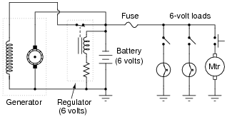
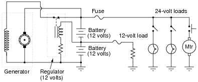
A mechanic has an idea for upgrading the electrical system in an automobile originally designed for 6 volt operation. He wants to upgrade the 6 volt headlights, starter motor, battery, etc, to 12 volts, but wishes to retain the original 6-volt generator and regulator. Shown here is the original 6-volt electrical system:
|
|
The mechanic's plan is to replace all the 6-volt loads with 12-volt loads, and use two 6-volt batteries connected in series, with the original (6-volt) regulator sensing voltage across only one of those batteries:
|
|
Explain how this system is supposed to work. Do you think the mechanic's plan is practical, or are there any problems with it?
Challenge question: identify factors that may prevent the generator from outputting enough voltage with the regulator connected as shown in the last diagram.
Notes:
In this question, we see a foreshadowing of op-amp theory, with the regulator's negative feedback applied to what is essentially a voltage divider (two equal-voltage batteries being charged by the generator). The regulator circuit senses only 6 volts, but the generator outputs 12 volts.
Fundamentally, the focus of this question is negative feedback and one of its many practical applications in electrical engineering. The depth to which you discuss this concept will vary according to the students' readiness, but it is something you should at least mention during discussion on this question.
This idea actually came from one of the readers of my textbook series Lessons In Electric Circuits. He was trying to upgrade a vehicle from 12 volts to 24 volts, but the principle is the same. An important difference in his plan was that he was still planning on having some 12-volt loads in the vehicle (dashboard gauges, starter solenoid, etc.), with the full 24 volts supplying only the high-power loads (such as the starter motor itself):
|
|
As a challenge for your students, ask them how well they think this system would work. It is a bit more complex than the system shown in the question, due to the two different load banks.
Question 6:
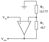
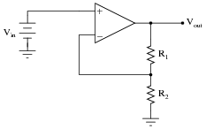
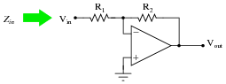
Calculate the overall voltage gain of this amplifier circuit (AV), both as a ratio and as a figure in units of decibels (dB). Also, write a general equation for calculating the voltage gain of such an amplifier, given the resistor values of R1 and R2:
|
|
|
Follow-up question: explain how you could modify this particular circuit to have a voltage gain (ratio) of 3 instead of 2.
Notes:
Nothing special here - just some practice with voltage gain calculations.
Question 7:
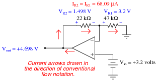
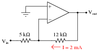
Calculate all voltage drops and currents in this circuit, complete with arrows for current direction and polarity markings for voltage polarity. Then, calculate the overall voltage gain of this amplifier circuit (AV), both as a ratio and as a figure in units of decibels (dB):
|
|
|
|
AV = 1.468 = 3.335 dB
Notes:
Operational amplifier circuits provide a great opportunity to review basic concepts of DC circuits: voltage drops, polarity, current directions, Ohm's Law, Kirchhoff's Voltage Law, Kirchhoff's Current Law, etc. This circuit is no exception. Emphasize the fact that a great many opamp circuits may be comprehensively analyzed merely with knowledge of these fundamental principles and the characteristics of an ideal opamp (zero input current, infinite open-loop gain, unlimited output voltage swing, zero voltage between input terminals when negative feedback is in effect).
Some students may arrive at the wrong gain figure because they blindly followed a formula with R1 and R2 shown as variables, plugging in this circuit's values for R1 and R2 without considering which resistor is which (is R1 the feedback resistor or is R2?). This is by design, as I want students to learn to think about what they are doing rather than thoughtlessly follow instructions.
Question 8:
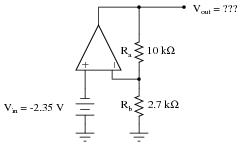
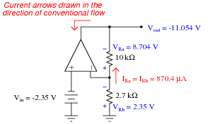
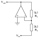
Calculate all voltage drops and currents in this circuit, complete with arrows for current direction and polarity markings for voltage polarity. Then, calculate the overall voltage gain of this amplifier circuit (AV), both as a ratio and as a figure in units of decibels (dB):
|
|
|
|
AV = 4.704 = 13.449 dB
Follow-up question: how much input impedance does the -2.35 volt source ßee" as it drives this amplifier circuit?
Notes:
Operational amplifier circuits provide a great opportunity to review basic concepts of DC circuits: voltage drops, polarity, current directions, Ohm's Law, Kirchhoff's Voltage Law, Kirchhoff's Current Law, etc. This circuit is no exception. Emphasize the fact that a great many opamp circuits may be comprehensively analyzed merely with knowledge of these fundamental principles and the characteristics of an ideal opamp (zero input current, infinite open-loop gain, unlimited output voltage swing, zero voltage between input terminals when negative feedback is in effect).
The follow-up question is important because it showcases one of the great advantages of using noninverting opamp amplifier circuits as voltage signal amplifiers: extremely high input impedance. This would be a good opportunity to review typical input impedance values for operational amplifiers, by showing datasheets for some typical opamps and for some non-typical (i.e. MOSFET input) opamps.
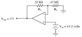
Question 9:
Determine both the input and output voltage in this circuit:
|
|
Notes:
Ask your students how they solved this problem, sharing techniques and strategies to help other students know where to begin and where to proceed from there.
Question 10:
What would have to be altered in this circuit to increase its overall voltage gain?
|
|
Notes:
Ask your students to explain how they would modify the voltage divider in this circuit to achieve the goal of a smaller voltage division ratio. This should be trivial, but it is always good to review basic principles of electricity even when "deep" into a more advanced topic.
Question 11:
The equation for voltage gain (AV) in a typical noninverting, single-ended opamp circuit is as follows:
|
Where,
R1 is the feedback resistor (connecting the output to the inverting input)
R2 is the other resistor (connecting the inverting input to ground)
Suppose we wished to change the voltage gain in the following circuit from 5 to 6.8, but only had the freedom to alter the resistance of R2:
|
|
Algebraically manipulate the gain equation to solve for R2, then determine the necessary value of R2 in this circuit to give it a voltage gain of 6.8.
|
For the circuit shown, R2 would have to be set equal to 810.3 W.
Notes:
Nothing more than a little algebra to obtain the answers for this question!
Question 12:
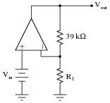
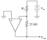
Calculate the necessary resistor value (R1) in this circuit to give it a voltage gain of 30:
|
|
Notes:
Ask your students how they solved this problem, especially since it is fairly safe to say that they didn't find the equation directly solving for R1 in any book. Algebraic manipulation is necessary to take the standard voltage gain equation and put it into a form suitable for use answering this question.
Question 13:
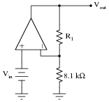
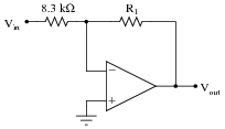
Calculate the necessary resistor value (R1) in this circuit to give it a voltage gain of 10.5:
|
|
Notes:
Ask your students how they solved this problem, especially since it is fairly safe to say that they didn't find the equation directly solving for R1 in any book. Algebraic manipulation is necessary to take the standard voltage gain equation and put it into a form suitable for use answering this question.
Question 14:
Predict how the operation of this operational amplifier circuit will be affected as a result of the following faults. Consider each fault independently (i.e. one at a time, no multiple faults):
|
|
- �
- Resistor R1 fails open:
- �
- Solder bridge (short) across resistor R1:
- �
- Resistor R2 fails open:
- �
- Solder bridge (short) across resistor R2:
- �
- Broken wire between R1/R2 junction and inverting opamp input:
For each of these conditions, explain why the resulting effects will occur.
- �
- Resistor R1 fails open: Output saturates positive.
- �
- Solder bridge (short) across resistor R1: Vout = Vin.
- �
- Resistor R2 fails open: Vout = Vin.
- �
- Solder bridge (short) across resistor R2: Output saturates positive.
- �
- Broken wire between R1/R2 junction and inverting opamp input: Output voltage unpredictable.
Notes:
The purpose of this question is to approach the domain of circuit troubleshooting from a perspective of knowing what the fault is, rather than only knowing what the symptoms are. Although this is not necessarily a realistic perspective, it helps students build the foundational knowledge necessary to diagnose a faulted circuit from empirical data. Questions such as this should be followed (eventually) by other questions asking students to identify likely faults based on measurements.
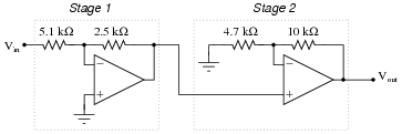
Question 15:
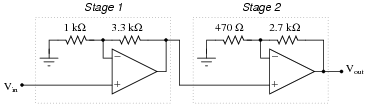
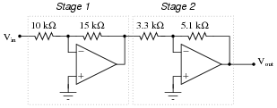
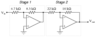
Calculate the voltage gain for each stage of this amplifier circuit (both as a ratio and in units of decibels), then calculate the overall voltage gain:
|
|
- Stage 1:
- �
- AV = 4.3 = 12.669 dB
- Stage 2:
- �
- AV = 6.745 = 16.579 dB
- Overall:
- �
- AV = 29.002 = 29.249 dB
Notes:
Not only does this question review calculation of voltage gain for inverting amplifier circuits, but it also reviews decibel calculations (for both single and multi-stage amplifiers). Discuss how the decibel figures for each stage add to equal the total decibel gain, whereas the ratios multiply.
Question 16:
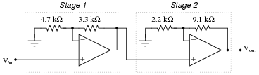
Calculate the voltage gain for each stage of this amplifier circuit (both as a ratio and in units of decibels), then calculate the overall voltage gain:
|
|
- Stage 1:
- �
- AV = 1.702 = 4.62 dB
- Stage 2:
- �
- AV = 5.136 = 14.213 dB
- Overall:
- �
- AV = 8.743 = 18.833 dB
Notes:
Not only does this question review calculation of voltage gain for inverting amplifier circuits, but it also reviews decibel calculations (for both single and multi-stage amplifiers). Discuss how the decibel figures for each stage add to equal the total decibel gain, whereas the ratios multiply.
Question 17:
How much effect will a change in the op-amp's open-loop voltage gain have on the overall voltage gain of a negative-feedback circuit such as this?
|
|
If the open-loop gain of this operational amplifier were to change from 100,000 to 200,000, for example, how big of an effect would it have on the voltage gain as measured from the noninverting input to the output?
Follow-up question: what advantage is there in building voltage amplifier circuits in this manner, applying negative feedback to a "core" amplifier with very high intrinsic gain?
Notes:
Work with your students to calculate a few example scenarios, with the old open-loop gain versus the new open-loop gain. Have the students validate their conclusions with numbers!
Negative feedback is an extremely useful engineering principle, and one that allows us to build very precise amplifiers using imprecise components. Credit for this idea goes to Harold Black, an electrical engineer, in 1920's. Mr. Black was looking for a way to improve the linearity and stability of amplifiers in telephone systems, and (as legend has it) the idea came to him in a flash of insight as he was commuting on a ferry boat.
An interesting historical side-note is that Black's 1928 patent application was initially rejected on the grounds that he was trying to submit a perpetual motion device! The concept of negative feedback in an amplifier circuit was so contrary to established engineering thought at the time, that Black experienced significant resistance to the idea within the engineering community. The United States patent office, on the other hand, was inundated with fraudulent "perpetual motion" claims, and so dismissed Black's invention at first sight.
Question 18:
Suppose a technician is checking the operation of the following electronic circuit:
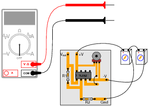
|
|
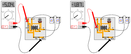
She decides to measure the voltage on either side of resistor R1 with reference to ground, and obtains these readings:
|
|
On the top side of R1, the voltage with reference to ground is -5.04 volts. On the bottom side of R1, the voltage with reference to ground is -1.87 volts. The color code of resistor R1 is Yellow, Violet, Orange, Gold. From this information, determine the following:
- �
- Voltage across R1 (between top to bottom):
- �
- Polarity (+ and -) of voltage across R1:
- �
- Current (magnitude) through R1:
- �
- Direction of current through R1:
Additionally, explain how this technician would make each one of these determinations. What rules or laws of electric circuits would she apply?
- �
- Voltage across R1 (between top to bottom): 3.17 volts
- �
- Polarity (+ and -) of voltage across R1: (-) on top, (+) on bottom
- �
- Current (magnitude) through R1: 67.45 mA
- �
- Direction of current through R1: upward, following conventional flow
Follow-up question: calculate the range of possible currents, given the specified tolerance of resistor R1 (67.45 mA assumes 0% error).
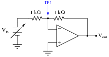
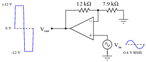
Challenge question: if you recognize the type of circuit this is (by the part number of the IC "chip": TL082), identify the voltage between pin 3 and ground.
Notes:
This is a good example of how Kirchhoff's Voltage Law is more than just an abstract tool for mathematical analysis - it is also a powerful technique for practical circuit diagnosis. Students must apply KVL to determine the voltage drop across R1, and then use Ohm's Law to calculate its current.
If students experience difficulty visualizing how KVL plays a part in the solution of this problem, show them this illustration:
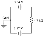
|
|
By the way, the answer to the challenge question may only be realized if students recognize this circuit as a noninverting opamp voltage amplifier. The voltage at pin 3 (noninverting input) will be the same as the voltage at pin 2 (inverting input): -1.87 volts.
Question 19:
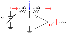
Trace the directions for all currents in this circuit, and calculate the values for voltage at the output (Vout) and at test point 1 (VTP1) for several values of input voltage (Vin):
|
|
-
Vin VTP1 Vout
0.0 V
0.4 V
1.2 V
3.4 V
7.1 V
10.8 V
Then, from the table of calculated values, determine the voltage gain (AV) for this amplifier circuit.
|
|
-
Vin VTP1 Vout
0.0 V 0.0 V 0.0 V
0.4 V 0.0 V -0.4 V
1.2 V 0.0 V -1.2 V
3.4 V 0.0 V -3.4 V
7.1 V 0.0 V -7.1 V
10.8 V 0.0 V -10.8 V
|
Follow-up question: the point marked "TP1" in this circuit is often referred to as a virtual ground. Explain why this is, based on the voltage figures shown in the above table.
Notes:
Some texts describe the voltage gain of an inverting voltage amplifier as being a negative quantity. I tend not to look at things that way, treating all gains as positive quantities and relying on my knowledge of circuit behavior to tell whether the signal is inverted or not. In my teaching experience, I have found that students have a tendency to blindly follow equations rather than think about what it is they are calculating, and that strict adherence to the mathematical signs of gain values only encourages this undesirable behavior (Ïf the sign of the gain tells me whether the circuit is inverting or not, I can just multiply input voltage by gain and the answer will always be right!").
This strategy is analogous to problem-solving in electromagnetics, where a common approach is to use math to solve for the absolute values of quantities (potential, induced voltage, magnetic flux), and then to use knowledge of physical principles (Lenz' Law, right-hand rule) to solve for polarities and directions. The alternative - to try to maintain proper sign convention throughout all calculations - not only complicates the math but it also encourages students to over-focus on calculations and neglect fundamental principles.
Question 20:
Calculate the overall voltage gain of this amplifier circuit (AV), both as a ratio and as a figure in units of decibels (dB). Also, write a general equation for calculating the voltage gain of such an amplifier, given the resistor values of R1 and R2:
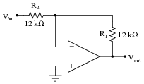
|
|
|
Follow-up question #1: sometimes the voltage gain equation for an amplifier of this type is given in the following form:
|
What is the significance of the negative sign in this equation? Is it really necessary, or does it communicate an important concept?
Follow-up question #2: manipulate the gain equation for this amplifier circuit to solve for the value of resistor R1.
Notes:
Whether inverting amplifier gains are expressed as negative or positive quantities seems to be a matter of taste, from surveying introductory textbooks on the subject. I prefer to stick with absolute (positive) gain values and consider signal inversion separately.
Question 21:
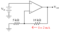
Calculate all voltage drops and currents in this circuit, complete with arrows for current direction and polarity markings for voltage polarity. Then, calculate the overall voltage gain of this amplifier circuit (AV), both as a ratio and as a figure in units of decibels (dB):
|
|
|
|
AV = 0.468 = -6.594 dB
Notes:
Operational amplifier circuits provide a great opportunity to review basic concepts of DC circuits: voltage drops, polarity, current directions, Ohm's Law, Kirchhoff's Voltage Law, Kirchhoff's Current Law, etc. This circuit is no exception. Emphasize the fact that a great many opamp circuits may be comprehensively analyzed merely with knowledge of these fundamental principles and the characteristics of an ideal opamp (zero input current, infinite open-loop gain, unlimited output voltage swing, zero voltage between input terminals when negative feedback is in effect).
Some students may arrive at the wrong gain figure because they blindly followed a formula with R1 and R2 shown as variables, plugging in this circuit's values for R1 and R2 without considering which resistor is which (is R1 the feedback resistor or is R2?). This is by design, as I want students to learn to think about what they are doing rather than thoughtlessly follow instructions.
Question 22:
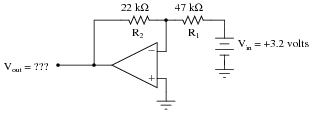
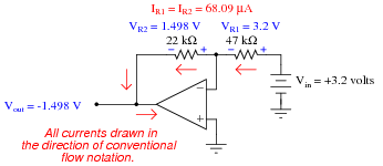
Determine both the input and output voltage in this circuit:
|
|
Follow-up question: how do we know that the input voltage in this circuit is negative and the output voltage is positive?
Notes:
Ask your students how they solved this problem, sharing techniques and strategies to help other students know where to begin and where to proceed from there.
Question 23:
The equation for voltage gain (AV) in a typical inverting, single-ended opamp circuit is as follows:
|
Where,
R1 is the feedback resistor (connecting the output to the inverting input)
R2 is the other resistor (connecting the inverting input to voltage signal input terminal)
Suppose we wished to change the voltage gain in the following circuit from 3.5 to 4.9, but only had the freedom to alter the resistance of R2:
|
|
Algebraically manipulate the gain equation to solve for R2, then determine the necessary value of R2 in this circuit to give it a voltage gain of 4.9.
|
For the circuit shown, R2 would have to be set equal to 1.571 kW.
Notes:
Nothing more than a little algebra to obtain the answers for this question!
Question 24:
Calculate the necessary resistor value (R1) in this circuit to give it a voltage gain of 15:
|
|
Notes:
Ask your students how they solved this problem, especially since it is fairly safe to say that they didn't find the equation directly solving for R1 in any book. Algebraic manipulation is necessary to take the standard voltage gain equation and put it into a form suitable for use answering this question.
Question 25:
Calculate the necessary resistor value (R1) in this circuit to give it a voltage gain of 7.5:
|
|
Notes:
Ask your students how they solved this problem, especially since it is fairly safe to say that they didn't find the equation directly solving for R1 in any book. Algebraic manipulation is necessary to take the standard voltage gain equation and put it into a form suitable for use answering this question.
Question 26:
Predict how the operation of this operational amplifier circuit will be affected as a result of the following faults. Consider each fault independently (i.e. one at a time, no multiple faults):
|
|
- �
- Resistor R1 fails open:
- �
- Solder bridge (short) across resistor R1:
- �
- Resistor R2 fails open:
- �
- Solder bridge (short) across resistor R2:
- �
- Broken wire between R1/R2 junction and inverting opamp input:
For each of these conditions, explain why the resulting effects will occur.
- �
- Resistor R1 fails open: Vout = 0 volts.
- �
- Solder bridge (short) across resistor R1: Output saturates negative.
- �
- Resistor R2 fails open: Output saturates negative.
- �
- Solder bridge (short) across resistor R2: Vout = 0 volts.
- �
- Broken wire between R1/R2 junction and inverting opamp input: Output voltage unpredictable.
Notes:
The purpose of this question is to approach the domain of circuit troubleshooting from a perspective of knowing what the fault is, rather than only knowing what the symptoms are. Although this is not necessarily a realistic perspective, it helps students build the foundational knowledge necessary to diagnose a faulted circuit from empirical data. Questions such as this should be followed (eventually) by other questions asking students to identify likely faults based on measurements.
Question 27:
There is something wrong with this amplifier circuit. Note the relative amplitudes of the input and output signals as measured by an oscilloscope:
|
|
This circuit used to function perfectly, but then began to malfunction in this manner: producing a "clipped" output waveform of excessive amplitude. Determine the approximate amplitude that the output voltage waveform should be for the component values given in this circuit, and then identify possible causes of the problem and also elements of the circuit that you know cannot be at fault.
I'll let you determine possible faults in the circuit! From what we see here, we know the power supply is functioning (both +V and -V rails) and that there is good signal getting to the noninverting input of the opamp.
Notes:
There is definitely more than one possible cause for the observed problem. Discuss alternatives with your students, involving them in the diagnosis process. Ask them why we know that certain elements of the circuit are functioning as they should? Of the possible causes, which are more likely, and why?
Question 28:
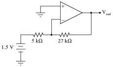
Calculate the output voltage of this op-amp circuit (using negative feedback):
|
|
Also, calculate the DC voltage gain of this circuit.
AV = 5.4
Follow-up question: the midpoint of the voltage divider (connecting to the inverting input of the op-amp) is often called a virtual ground in a circuit like this. Explain why.
Notes:
It is important that students learn to analyze the op-amp circuit in terms of voltage drops and currents for each resistor, rather than just calculate the output using a gain formula. Detailed, Ohm's Law analysis of op-amp circuits is essential for analyzing more complex circuitry.
The "virtual ground" question is an important one for the sake of rapid analysis. Once students understand how and why there is such a thing as a "virtual ground" in an op-amp circuit like this, their analysis of op-amp circuits will be much more efficient.
Question 29:
Calculate the voltage gain for each stage of this amplifier circuit (both as a ratio and in units of decibels), then calculate the overall voltage gain:
|
|
- Stage 1:
- �
- AV = 1.5 = 3.522 dB
- Stage 2:
- �
- AV = 1.545 = 3.781 dB
- Overall:
- �
- AV = 2.318 = 7.303 dB
Notes:
Not only does this question review calculation of voltage gain for inverting amplifier circuits, but it also reviews decibel calculations (for both single and multi-stage amplifiers). Discuss how the decibel figures for each stage add to equal the total decibel gain, whereas the ratios multiply.
Question 30:
Calculate the voltage gain for each stage of this amplifier circuit (both as a ratio and in units of decibels), then calculate the overall voltage gain:
|
|
- Stage 1:
- �
- AV = 1.766 = 4.940 dB
- Stage 2:
- �
- AV = 0.455 = -6.848 dB
- Overall:
- �
- AV = 0.803 = -1.909 dB
Notes:
Not only does this question review calculation of voltage gain for inverting amplifier circuits, but it also reviews decibel calculations (for both single and multi-stage amplifiers). Discuss how the decibel figures for each stage add to equal the total decibel gain, whereas the ratios multiply.
Question 31:
What possible benefit is there to adding a voltage buffer to the front end of an inverting amplifier, as shown in the following schematic?
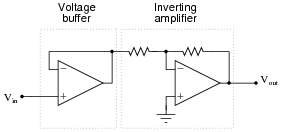
|
|
Notes:
Discuss with your students how this is very common: using a voltage buffer as an impedance transformation (or isolation) device so that a weak (high-impedance) source is able to drive an amplifier.
Question 32:
Operational amplifier circuits employing negative feedback are sometimes referred to as ëlectronic levers," because their voltage gains may be understood through the mechanical analogy of a lever. Explain this analogy in your own words, identifying how the lengths and fulcrum location of a lever relate to the component values of an op-amp circuit:
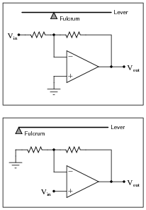
|
|
Notes:
I found this analogy in one of the best books I've ever read on op-amp circuits: John I. Smith's Modern Operational Circuit Design. Unfortunately, this book is out of print, but if you can possibly obtain a copy for your library, I highly recommend it!
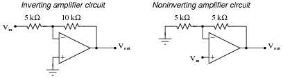
Question 33:
Compare and contrast inverting versus noninverting amplifier circuits constructed using operational amplifiers:
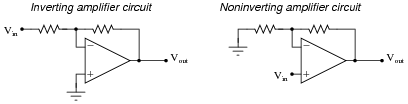
|
|
How do these two general forms of opamp circuit compare, especially in regard to input impedance and the range of voltage gain adjustment?
Notes:
Just a simple comparison between amplifier configurations, nothing more. Ask your students to elaborate on the inverting amplifier's range of gain adjustment: how does it differ from the noninverting configuration?
Question 34:
Predict how the input impedance (Zin) of this inverting operational amplifier circuit will be affected as a result of the following faults. Consider each fault independently (i.e. one at a time, no multiple faults):
|
|
- �
- Resistor R1 fails open:
- �
- Solder bridge (short) across resistor R1:
- �
- Resistor R2 fails open:
- �
- Solder bridge (short) across resistor R2:
- �
- Broken wire between R1/R2 junction and inverting opamp input:
- �
- Operational amplifier loses power:
For each of these conditions, explain why the input impedance changes as it does.
- �
- Resistor R1 fails open: Zin increases to infinity.
- �
- Solder bridge (short) across resistor R1: Zin decreases to (nearly) zero.
- �
- Resistor R2 fails open: Zin increases to (nearly) infinity.
- �
- Solder bridge (short) across resistor R2: Zin remains equal in value to R1, as normal.
- �
- Broken wire between R1/R2 junction and inverting opamp input: Zin increases to (approximately) R1 + R2.
- �
- Operational amplifier loses power: Zin increases to (nearly) infinity.
Notes:
The purpose of this question is to approach the domain of circuit troubleshooting from a perspective of knowing what the fault is, rather than only knowing what the symptoms are. Although this is not necessarily a realistic perspective, it helps students build the foundational knowledge necessary to diagnose a faulted circuit from empirical data. Questions such as this should be followed (eventually) by other questions asking students to identify likely faults based on measurements.
Question 35:
Calculate the voltage gain for each stage of this amplifier circuit (both as a ratio and in units of decibels), then calculate the overall voltage gain:
|
|
- Stage 1:
- �
- AV = 0.490 = -6.193 dB
- Stage 2:
- �
- AV = 3.128 = 9.904 dB
- Overall:
- �
- AV = 1.533 = 3.712 dB
Follow-up question: is this circuit inverting or noninverting, overall?
Notes:
Not only does this question review calculation of voltage gain for inverting amplifier circuits, but it also reviews decibel calculations (for both single and multi-stage amplifiers). Discuss how the decibel figures for each stage add to equal the total decibel gain, whereas the ratios multiply.
Question 36:
Shown here are two different voltage amplifier circuits with the same voltage gain. Which of them has greater input impedance, and why? Try to give as specific an answer for each circuit's input impedance as possible.
|
|
Notes:
If students have difficulty grasping the concept of input impedance, and how to figure that out for circuits such as these, remind them that input impedance is fundamentally defined by the following equation:
|
With this in mind, encourage them to set up a "thought experiment" by where they assume a given input voltage and analyze the circuit step-by-step using Ohm's Law, Kirchhoff's Laws, and the basic rules of closed-loop, negative feedback opamp behavior. The results of the "thought experiment" should conclusively demonstrate which circuit has the greater input impedance.
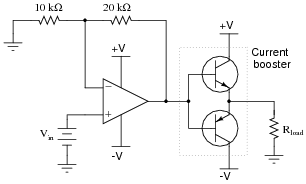
Question 37:
A simple "follower" circuit that boosts the current-output ability of this noninverting amplifier circuit is a set of bipolar junction transistors, connected together in a "push-pull" fashion like this:
|
|
However, if connected exactly as shown, there will be a significant voltage error introduced to the opamp's output. No longer will the final output voltage (measured across the load) be an exact 3:1 multiple of the input voltage, due to the 0.7 volts dropped by the transistor in active mode:
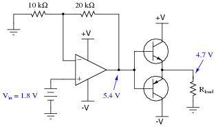
|
|
There is a very simple way to completely eliminate this error, without adding any additional components. Modify the circuit accordingly.
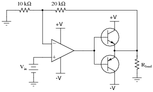
|
|
If you understand why this circuit works, pat yourself on the back: you truly understand the self-correcting nature of negative feedback. If not, you have a bit more studying to do!
Notes:
The answer is not meant to be discouraging for those students of yours who do not understand how the solution works. It is simply a "litmus test" of whether or not your students really comprehend the concept of negative feedback. Although the change made in the circuit is simple, the principle is a bit of a conceptual leap for some people.
It might help your students understand if you label the new wire with the word sense, to indicate its purpose of providing feedback from the very output of the circuit, back to the opamp so it can sense how much voltage the load is receiving.
Question 38:
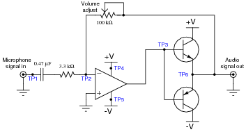
A student wishes to build a variable-gain amplifier circuit using an operational amplifier and a potentiometer. The purpose of this circuit is to act as an audio amplifier for a small speaker, so he can listen to the output of a digital audio player without having to use headphones:
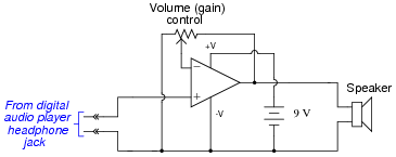
|
|
Before building the project in a finalized form, the student prototypes it on a solderless breadboard to make sure it functions as intended. And it is a good thing he decided to do this before wasting time on a final version, because it sounds terrible!
When playing a song, the student can hear sound through the headphones, but it is terribly distorted. Taking the circuit to his instructor for help, the instructor suggests the following additions:
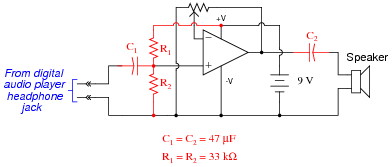
|
|
After adding these components, the circuit works great. Now, music may be heard through the speaker with no noticeable distortion.
Explain what functions the extra components perform, and why the circuit did not work as originally built.
Notes:
This question illustrates a common problem in opamp circuit design and usage: it is easy for students to overlook the importance of considering the power supply rail voltages. Despite the fact that the rails are labeled "+V" and "-V" at the opamp chip terminals, the input signal is actually referenced to the negative side of the power supply, which means that every negative half-cycle of the input voltage goes beyond the -V power supply rail voltage, and the opamp cannot handle that.
The instructor's solution to this problem should look very similar to voltage divider biasing in a single-transistor circuit, providing a good opportunity to review that concept with your students.
Some students may ask where the second speaker is, for stereo sound. If they do, tell them that this circuit only represents one channel's worth of amplification, and that the other channel's circuit would look just the same. If a single volume control were desired to control the gain of both amplifier circuits, a dual-ganged potentiometer could be used (another point of discussion for your students!).
Question 39:
There is something wrong with this amplifier circuit. Despite an audio signal of normal amplitude detected at test point 1 (TP1), there is no output measured at the Äudio signal out" jack:
|
|
Next, you decide to check for the presence of a good signal at test point 3 (TP3). There, you find 0 volts AC and DC no matter where the volume control is set.
From this information, formulate a plan for troubleshooting this circuit, answering the following questions:
- �
- What type of signal would you expect to measure at TP3?
- �
- What would be your next step in troubleshooting this circuit?
- �
- Are there any elements of this circuit you know to be working properly?
- �
- What do you suppose would be the most likely failure, assuming this circuit once worked just fine and suddenly stopped working all on it's own?
Notes:
I have found that troubleshooting scenarios are always good for stimulating class discussions, with students posing strategies for isolating the fault(s) and correcting one another on logical errors. There is not enough information given in this question to ensure a single, correct answer. Discuss this with your students, helping them to use their knowledge of circuit theory and opamps to formulate good diagnostic strategies.
Question 40:
The junction between the two resistors and the inverting input of the operational amplifier is often referred to as a virtual ground, the voltage between it and ground being (almost) zero over a wide range of circuit conditions:
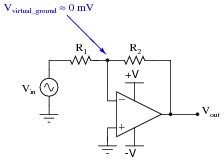
|
|
If the operational amplifier is driven into saturation, though, the "virtual ground" will no longer be at ground potential. Explain why this is, and what condition(s) may cause this to happen.
Hint: analyze all currents and voltage drops in the following circuit, assuming an opamp with the ability to swing its output voltage rail-to-rail.
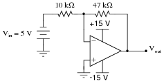
|
|
Notes:
Before students can answer this question, they must understand what saturation means with regard to an operational amplifier. This is where the "hint" scenario comes into play. Students failing to grasp this concept will calculate the voltage drops and currents in the "hint" circuit according to standard procedures and assumptions, and arrive at an output voltage well in excess of +15 volts. Resolving this paradox will lead to insight, and hopefully to a more realistic set of calculations.
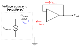
Question 41:
The same problem of input bias current affecting the precision of opamp voltage buffer circuits also affects noninverting opamp voltage amplifier circuits:
|
|
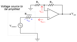
|
|
To fix this problem in the voltage buffer circuit, we added a "compensating" resistor:
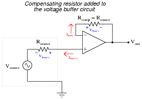
|
|
To fix the same problem in the noninverting voltage amplifier circuit, we must carefully choose resistors R1 and R2 so that their parallel equivalent equals the source resistance:
|
Of course, we must also be sure the values of R1 and R2 are such that the voltage gain of the circuit is what we want it to be.
Determine values for R1 and R2 to give a voltage gain of 7 while compensating for a source resistance of 1.45 kW.
Notes:
Students must apply algebra to solve for the values of these two resistances. The solution is an application of algebraic substitution, and it is worthwhile to examine and discuss together in class.
Discuss how this solution to the bias current problem is a practical application of Thévenin's theorem: looking at the two voltage divider resistors as a network that may be Thévenized to serve as a compensating resistance as well as a voltage divider for the necessary circuit gain.