Phase-locked loops
Question 1:
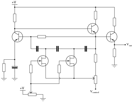
This is a schematic for a simple VCO:
|
|
The oscillator is of the RC "phase shift" design. Explain how this circuit works. Why does the output frequency vary as the control voltage varies? Does the output frequency increase or decrease as the control voltage input receives a more positive voltage?
Hint: the JFETs in this circuit are not functioning as amplifiers!
The output frequency decreases as the control voltage becomes more positive.
Notes:
Not only does this question allow students to examine the workings of a VCO, but it also provides a good review of JFET theory, as well as a practical example of a special application of junction field-effect transistors.
Note: the schematic diagram for this circuit was derived from one found on page 997 of John Markus' Guidebook of Electronic Circuits, first edition. Apparently, the design originated from a Motorola publication on using field effect transistors ("Low Frequency Applications of Field-Effect Transistors," AN-511, 1971).
Question 2:
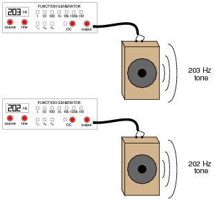
If you have ever heard the sound of a dual-engine airplane flying overhead, you probably noticed an unusual "beat" pattern to the engines' tone. The same phenomenon happens when you play the output of two audio signal generators through speakers, with the signal generators set to very similar (but not identical!) frequencies:
|
|
Explain how this phenomenon could be used by a technician to adjust two audio frequency sources to the same frequency, without the aid of any expensive test equipment such as a frequency counter or an oscilloscope.
Notes:
This is a very simple experiment to set up in the classroom, but beware! I once had two audio signal generators creating low-frequency sine-wave tones for my students, shortly after their lunch break. With full stomachs, a couple of my students had a very difficult time remaining awake while listening to the low tones.
Question 3:
What is a VCO?
Notes:
Ask your students how a VCO might be used in a circuit. What, exactly, does "voltage controlled" mean?
Question 4:
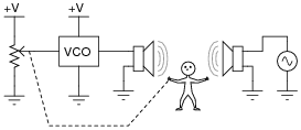
Suppose a technician connected a potentiometer to the input of a VCO, to act as a manually-variable voltage source. Then, the technician compares the output of the VCO with an external signal source that slowly changes frequency, adjusting the potentiometer to keep the two frequencies equal:
|
|
If a voltmeter were connected between the potentiometer wiper and ground, what would its indication represent (with regard to the external audio signal)?
Explain where feedback occurs in this system, and how the system may be automated so as to not require the continual attention of a technician.
Notes:
Tell your students that voltage-controlled oscillators are sometimes called voltage-to-frequency converters. Then, ask them to explain how the presence of feedback in this system provides a frequency-to-voltage conversion function.
The question regarding automation of this system may be challenging for some of your students. If they cannot give a technical answer for this question, ask them to explain ïn layman's terms" what the additional components must do. Accurately identifying the function of a human operator is the first step in designing an automation system!
Question 5:
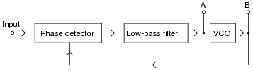
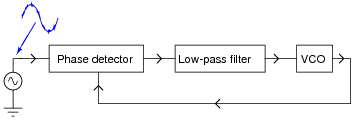
A block diagram of a phase-locked loop circuit looks like this:
|
|
Determine what type of electronic signals would be seen at points A and B for the following input conditions:
- �
- Input = sine wave, steady frequency
- �
- Input = sine wave, increasing frequency
- �
- Input = sine wave, decreasing frequency
- �
- Input = sine wave, frequency increases and decreases regularly
- �
- Input = sine wave, steady frequency
- -
- A: Steady DC voltage
- -
- B: frequency equal to input signal
- �
- Input = sine wave, increasing frequency
- -
- A: Increasing DC voltage
- -
- B: frequency equal to input signal
- �
- Input = sine wave, decreasing frequency
- -
- A: Decreasing DC voltage
- -
- B: frequency equal to input signal
- �
- Input = sine wave, frequency increases and decreases regularly
- -
- A: DC voltage that rises and falls with input frequency
- -
- B: frequency equal to input signal
Notes:
The purpose of this question is to get students to recognize the function of each "block" in a phase-locked loop. Having them predict the types of output signals at points A and B for different input signal conditions reveals whether or not they understand the concept.
Ask them where they obtained their information on phase-locked loop operation. I've seen quite a few tutorials on the internet for this subject, so there should be no problem with students finding sources.
Question 6:
Suppose that a "noisy" AC signal of otherwise constant frequency is connected to the input of a phase-locked loop circuit:
|
|
Characterize the output waveform generated by the VCO. Will it be "noisy" as well? Why or why not?
Notes:
Ask your students how this behavior of the PLL circuit could be advantageous. What practical purpose(s) can students think of for a PLL, used as such?
Question 7:
Define the following terms, as they relate to phase-locked loop circuits:
- �
- Center frequency
- �
- Lock range
- �
- Capture range
- �
- Lock-up time
- �
- Center frequency: the "free-running" frequency of a PLL's voltage-controlled oscillator.
- �
- Lock range: the range of input signal frequencies that a PLL is able to remain "locked in" to.
- �
- Capture range: the range of input signal frequencies that a PLL is able to lock in to, from an unlocked state.
- �
- Lock-up time: the amount of time required for a PLL to "lock in" to a given input frequency, from a cold start.
Notes:
Ask your students to explain which range - lock or capture - is narrower, and why.
Question 8:
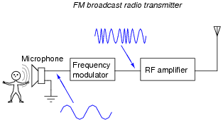
"FM" means "frequency modulation," and it refers to the encoding of a waveform by changing (modulating) the frequency of another. This is the technology used in broadcast FM radio transmission:
|
|
This is how FM radio communication works: by modulating the frequency of a radio-frequency (RF) signal according to the amplitude of the voltage signal produced by a microphone.
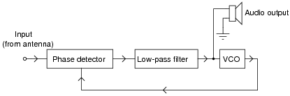
Explain how a phase-locked loop circuit could be used to "demodulate" the output of an FM radio station, so as to extract the broadcaster's audio signal from the RF waveform.
|
|
Notes:
Despite the crudeness of the answer given, the basic operational theory of a PLL demodulator should be apparent for students to see. Discuss the operation of this circuit with your students, making sure all of them comprehend the purpose of a PLL.