Potentiometers
Question 1:
| Don't just sit there! Build something!! |
Learning to mathematically analyze circuits requires much study and practice. Typically, students practice by working through lots of sample problems and checking their answers against those provided by the textbook or the instructor. While this is good, there is a much better way.
You will learn much more by actually building and analyzing real circuits, letting your test equipment provide the änswers" instead of a book or another person. For successful circuit-building exercises, follow these steps:
- 1.
- Carefully measure and record all component values prior to circuit construction.
- 2.
- Draw the schematic diagram for the circuit to be analyzed.
- 3.
- Carefully build this circuit on a breadboard or other convenient medium.
- 4.
- Check the accuracy of the circuit's construction, following each wire to each connection point, and verifying these elements one-by-one on the diagram.
- 5.
- Mathematically analyze the circuit, solving for all values of voltage, current, etc.
- 6.
- Carefully measure those quantities, to verify the accuracy of your analysis.
- 7.
- If there are any substantial errors (greater than a few percent), carefully check your circuit's construction against the diagram, then carefully re-calculate the values and re-measure.
Avoid very high and very low resistor values, to avoid measurement errors caused by meter "loading". I recommend resistors between 1 kW and 100 kW, unless, of course, the purpose of the circuit is to illustrate the effects of meter loading!
One way you can save time and reduce the possibility of error is to begin with a very simple circuit and incrementally add components to increase its complexity after each analysis, rather than building a whole new circuit for each practice problem. Another time-saving technique is to re-use the same components in a variety of different circuit configurations. This way, you won't have to measure any component's value more than once.
Notes:
It has been my experience that students require much practice with circuit analysis to become proficient. To this end, instructors usually provide their students with lots of practice problems to work through, and provide answers for students to check their work against. While this approach makes students proficient in circuit theory, it fails to fully educate them.
Students don't just need mathematical practice. They also need real, hands-on practice building circuits and using test equipment. So, I suggest the following alternative approach: students should build their own "practice problems" with real components, and try to mathematically predict the various voltage and current values. This way, the mathematical theory "comes alive," and students gain practical proficiency they wouldn't gain merely by solving equations.
Another reason for following this method of practice is to teach students scientific method: the process of testing a hypothesis (in this case, mathematical predictions) by performing a real experiment. Students will also develop real troubleshooting skills as they occasionally make circuit construction errors.
Spend a few moments of time with your class to review some of the "rules" for building circuits before they begin. Discuss these issues with your students in the same Socratic manner you would normally discuss the worksheet questions, rather than simply telling them what they should and should not do. I never cease to be amazed at how poorly students grasp instructions when presented in a typical lecture (instructor monologue) format!
A note to those instructors who may complain about the "wasted" time required to have students build real circuits instead of just mathematically analyzing theoretical circuits:
What is the purpose of students taking your course?
If your students will be working with real circuits, then they should learn on real circuits whenever possible. If your goal is to educate theoretical physicists, then stick with abstract analysis, by all means! But most of us plan for our students to do something in the real world with the education we give them. The "wasted" time spent building real circuits will pay huge dividends when it comes time for them to apply their knowledge to practical problems.
Furthermore, having students build their own practice problems teaches them how to perform primary research, thus empowering them to continue their electrical/electronics education autonomously.
In most sciences, realistic experiments are much more difficult and expensive to set up than electrical circuits. Nuclear physics, biology, geology, and chemistry professors would just love to be able to have their students apply advanced mathematics to real experiments posing no safety hazard and costing less than a textbook. They can't, but you can. Exploit the convenience inherent to your science, and get those students of yours practicing their math on lots of real circuits!
Question 2:
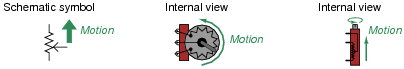
A very common misconception students have about potentiometers is the relationship between resistance and direction of wiper motion. For instance, it is common to hear a student say something like this, "Turning the potentiometer so the wiper moves up will increase the resistance of the potentiometer."
|
|
Explain why it does not really make sense to say something like this.
Notes:
Ask your students to identify which resistance (which two connection points on the potentiometer) increases and which decreases, and how they know this from the ïnternal views" of the potentiometers. This is a very important thing for your students to learn.
Year after year of teaching has revealed that a great many students have difficulty grasping this concept. This is especially true when they become accustomed to using a potentiometer as a rheostat and not as a voltage divider. The more you can make them think carefully about the operation of a potentiometer, the better!
Question 3:
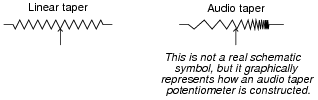
Potentiometers are manufactured in two different "tapers": linear and audio. Linear taper potentiometers provide a direct, linear relationship between wiper position and resistance division, so that equal changes in wiper position result in equal changes in resistance. Audio taper potentiometers provide a non-linear (logarithmic, to be exact) relationship between wiper position and resistance division, so that the same amount of wiper motion at one end of its range gives a much greater change in resistance than at the other end of its range.
|
|
Suppose you have a potentiometer, but do not know whether it has a linear or audio taper. How could you determine this, using a meter?
Notes:
Discuss with your students the purpose of an audio taper potentiometer: to provide logarithmically proportioned increases in audio power for volume control applications. This is necessary for a "proportional" response when turning the volume knob on an audio amplifier, since human hearing is not linear, but logarithmic in its detection of loudness. In order to generate a sound that the human ear perceives as twice as loud, ten times as much sound power is necessary.
A challenging question to ask your students is which way an audio taper potentiometer should be connected as a voltage divider in an audio amplifier circuit. Being that audio taper potentiometers are non-symmetrical, it truly matters which way they are connected!
Question 4:
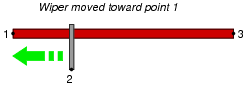
Suppose a length of resistive material (such as nichrome wire) had three points of electrical contact: one at each end (points 1 and 3), plus a movable metal "wiper" making contact at some point between the two ends (point 2):

|
|
Describe what happens to the amount of electrical resistance between the following points, as the wiper is moved toward the left end of the resistive element (toward point 1)? State your answers in terms of ïncrease," "decrease," or "remains the same," and explain why each answer is so.
|
|
- �
- Between points 1 and 2, resistance . . .
- �
- Between points 2 and 3, resistance . . .
- �
- Between points 1 and 3, resistance . . .
- �
- Between points 1 and 2, resistance decreases
- �
- Between points 2 and 3, resistance increases
- �
- Between points 1 and 3, resistance remains the same
Notes:
The purpose of this question is to get students to comprehend the function of a potentiometer, before they have ever seen one.
Question 5:
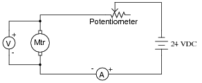
A technician decides to use a potentiometer as a speed control for an electric motor. The potentiometer has a resistance rating of 10 W and a power rating of 25 watts:
|
|
When operating the motor at a voltage of 16 volts and a current of 2 amps, though, smoke begins to pour out of the potentiometer, indicating that its power rating is being exceeded.
The technician is perplexed! According to his calculations, the potentiometer should be dissipating less than 25 watts of power. Why, then, is a potentiometer rated for 25 watts burning up under this condition?
Challenge question: based on the voltage and current values measured in this circuit (16 volts across the motor, 24 volts from the source, and 2 amps of current through it all), determine how badly the potentiometer is being overpowered. In other words, calculate the de-rated power rating of the potentiometer and compare that against the amount of power it is actually dissipating in this condition.
Notes:
A very practical and important lesson, learned after watching students send many potentiometers to an early demise.
In order to answer the challenge question, students must determine the pot's setting as a percentage between 0% (0 W) and 100% (10 W), and use that setting to estimate power de-rating. It is safe to assume a linear power derating proportional to wiper position.
Question 6:
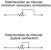
When potentiometers are used as variable resistors (rheostats), the unused terminal is often connected to the wiper terminal:
|
|
Explain what advantage is gained by connecting the wiper to the unused terminal. Why is the lower potentiometer connection scheme more commonly used than the upper?
Notes:
This is an example of "defensive engineering": designing something with eventual failure in mind, with the goal of minimizing the consequences of that inevitable failure. Whether your students go on to become engineers, or simply technicians, it is important for them to think past the immediate application and design issues, to consider what may happen as their system ages.
Question 7:
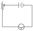
Draw a schematic diagram showing a potentiometer being used as a simple variable resistor for varying current to a light bulb. Also, designate which way the "wiper" should be moved to make the bulb glow brighter.
|
|
Notes:
Make note of the fact that only two of the potentiometer's three terminals need be used if a simple variable resistor is desired.
Question 8:
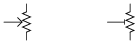
What is the difference between the following potentiometers, as indicated by their respective symbols?
|
|
Notes:
Ahhh, the joy of symbols! Do not be surprised if students are able to dredge up all kinds of electronic component symbols from symbol libraries you've never seen before.
Question 9:
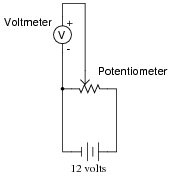
What would you expect the voltmeter in the following circuit to do when the potentiometer wiper is moved to the right?
|
|
What would you expect the voltmeter to register if the wiper were set precisely at the 50% (half-way) position?
Follow-up question: a useful problem-solving method is to imagine multiple "test case" scenarios, sometimes referred to as thought experiments, for the purpose of identifying a trend. For instance, in this circuit you might imagine what the voltmeter would register with the wiper moved all the way to the left, and then with the wiper moved all the way to the right. Identify the voltmeter's readings in these two scenarios, and then explain why the analysis of "test cases" like these are useful in problem-solving.
Notes:
Ask your students to describe possible applications for a circuit like this. Where might we wish to utilize a potentiometer in such a way that it outputs a variable voltage, from a constant voltage source?
Question 10:
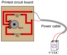
Connect the necessary wires in this illustration to make the potentiometer act as a variable voltage divider, providing a variable voltage to the voltmeter:
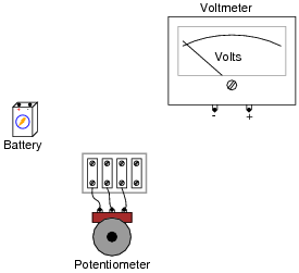
|
|
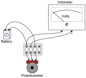
|
|
Here's a hint for those unfamiliar with the internal construction of rotary potentiometers:

|
|
Notes:
A good follow-up question to this would be to ask your students which way the potentiometer knob needs to be turned in order to increase the voltage applied to the meter.
Question 11:
With a trough of water and three pieces of wire, you could make a liquid potentiometer:
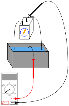
|
|
Which way would you have to move the middle wire (the one touching the voltmeter's red test lead) in order to increase the voltmeter's reading?
Follow-up question: identify any advantages and disadvantages of such a "liquid pot" over standard potentiometers using solid pieces. Are there any potential safety hazards that occur to you as you look at the illustration of this liquid potentiometer?
Notes:
Believe it or not, I have actually seen an application in industry where a "liquid rheostat" (not a potentiometer, but close) was used rather than a device made from solid parts. Very interesting. Very dangerous as well, since it was being used as part of a large motor speed control circuit, handling many amps of current at potentially deadly voltages! I do not know what maniac thought of building this contraption, but it was built and had been working for a number of years.
Question 12:
Which way would you have to move the potentiometer wiper, to the left or to the right, in order to increase current through resistor R1?
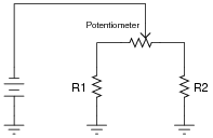
|
|
Follow-up question: what would happen to the current through resistor R2 as you moved the wiper in that direction (closer to resistor R1)?
Notes:
This circuit is fairly self-explanatory.
Question 13:
Which way would you have to twist the potentiometer shaft in order to increase current through resistor R1, clockwise or counter-clockwise? Explain your answer.
|
|
Here's a hint for those unfamiliar with the internal construction of rotary potentiometers:
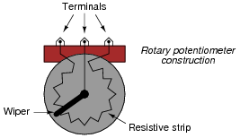
|
|
Notes:
This circuit is fairly self-explanatory, but getting the answer correct requires that you understand how a rotary potentiometer is constructed inside.
Question 14:
This current divider circuit has a problem. The voltage between test points TP2 and TP1 varies with the potentiometer position, but the voltage between test points TP3 and TP1 remains at 0 volts no matter where the potentiometer is set:
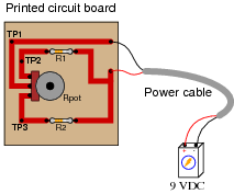
|
|
Identify the most likely fault which would account for these measurements.
Follow-up question: identify which direction of potentiometer shaft motion (clockwise or counter-clockwise) should increase the voltage between test points TP2 and TP1.
Notes:
Discuss with your students how they determined the identity of the fault. Also, be sure to discuss the follow-up question with them: how to determine the proper direction to turn the potentiometer shaft in order to increase VTP2-TP1. It is important that your students realize how a 3/4 turn potentiometer works, and what to expect when the shaft is turned.
Question 15:
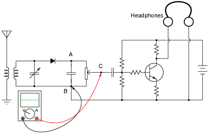
A radio technician is troubleshooting a problem in a simple AM receiver, using a voltage-measuring device called an oscilloscope. An oscilloscope is nothing more than a graphical voltmeter, indicating the "wave shape" of voltages that change rapidly over time. The problem with this radio is that no sound at all is heard in the headphones.
When checking for a voltage signal between points A and B in the circuit, a strong signal is obtained:
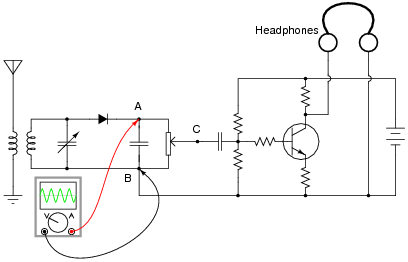
|
|
However, when checking between points C and B in the circuit, no signal is measured:
|
|
What do these voltage measurements indicate about the nature of the problem in the receiver circuit? Is there a general troubleshooting rule that may be drawn from this example? If so, what is it?
If possible, identify the precise nature of the failure.
Notes:
Do not worry if your students have not studied inductors, capacitors, diodes, transistors, amplifiers, or radio theory yet. This problem focuses on the potentiometer's function, and that is all your students have to understand in order to determine an answer.
It is very important for electronics technicians to be able to isolate portions of circuits they do understand from portions they do not, and perform as much diagnostic work as they can based on what they know. For this reason, I believe it is a good practice to show beginning students problems such as this, where they are challenged to see beyond the complexity of the circuit, to focus only on those portions that matter. On the job, I was frequently challenged with troubleshooting large, complex systems that I had no hope of understanding the entirety of, but which I knew enough about to isolate the problem to sections I could repair proficiently.
Ask your students to identify where, exactly, they think the potentiometer could have failed in order to cause this particular problem. Not just any fault within the potentiometer will result in the same loss of signal!
Question 16:
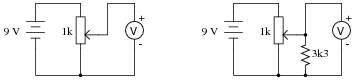
Calculate the voltmeter voltage in each of these circuits, assuming the wiper position is 25% up from the bottom:
|
|
Voltmeter in right-hand circuit = 2.13 volts
Notes:
Challenge your students to explain the significance of the reduced voltage from the potentiometer in the presence of a load (the 3.3 kW resistor). What impact could this effect have on a circuit we might build, where we expect the potentiometer to output a certain voltage corresponding to a specific wiper position?
Question 17:
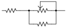
Suppose we were building a circuit that required an adjustable resistance with a range of 1500 W to 4500 W. The only potentiometer we have on hand is a 10 kW unit. Of course, we could simply connect the potentiometer as-is and have an adjustable range of 0 W to 10,000 W, but that would be too "coarse" of an adjustment for our application.
Explain how we could connect other resistors to this 10 kW potentiometer in order to achieve the desired adjustable resistance range.
|
|
Notes:
Knowing how to limit the adjustable range of a potentiometer is a very useful skill when designing and building circuits where precision of adjustment is important. The only drawback to building such a sub-circuit is that the adjustment becomes nonlinear (i.e., setting the potentiometer to the half-way position does not result in the total resistance being 50% of the way between the lower and upper range values).
Question 18:
Find one or two real potentiometers and bring them with you to class for discussion. Identify as much information as you can about your potentiometers prior to discussion:
- �
- Resistance (ideal)
- �
- Resistance (actual)
- �
- Taper (linear or audio)
- �
- Number of turns
- �
- Power rating
- �
- Type (carbon composition, wire-wound, etc.)
Be prepared to prove the type of taper that your potentiometers have in class, by using a multimeter!
Notes:
The purpose of this question is to get students to kinesthetically interact with the subject matter. It may seem silly to have students engage in a ßhow and tell" exercise, but I have found that activities such as this greatly help some students. For those learners who are kinesthetic in nature, it is a great help to actually touch real components while they're learning about their function. Of course, this question also provides an excellent opportunity for them to practice interpreting component markings, use a multimeter, access datasheets, etc.