Design Project: DC motor
Question 1:
The armature windings of your DC motor will have very low resistance. Too low, in fact, to accurately measure with an ohmmeter connected directly to the commutator terminals, because the contact resistance between the meter probes and terminals will be a large percentage of the resistance read by the meter.
One way to avoid this contact resistance problem and measure very low resistances using normal meters is to employ what is known as the Kelvin resistance measurement technique: measuring the voltage dropped by the low-resistance element when a substantial DC current is passed through it.
Draw a diagram showing how this measurement technique works, and explain why it works.
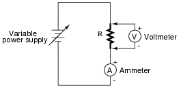
|
|
R is calculated by way of Ohm's Law.
Notes:
Kelvin resistance measurement is a very common technique used in electrical metrology, because it neatly sidesteps the problem of contact resistance in the path of high current. It is a technique well worth learning for the serious student of electronics.
Question 2:
If we apply Ohm's Law to the calculation of armature current, based on the applied voltage and the known armature winding resistance, we obtain a value for current that far exceeds the value of current measured when the motor is running at speed. Explain why this is.
Notes:
Once students understand this phenomenon, they will comprehend why electric motors of all kinds draw massive amounts of current when first started ("inrush current"), but do not when running at full speed. Being able to see this first-hand is a great educational experience for most students.
Question 3:
You will notice that a very important factor in your motor's performance is the brush angle: the points of contact that the brushes make with the commutator bars, as compared to the axis of the field magnets. What brush angle results in maximum unloaded motor speed? Why can't we just have the brushes contact the commutator bars at any arbitrary angle?
I cannot provide an öptimum" brush angle as an answer here, because that will vary with the specific design of your motor.
Notes:
Students are often fascinated with the effect that different brush contact angles have on motor performance, often spending hours of time experimenting to find the ßweet spot" for their particular motors.