Design Project: intercom system
Question 1:
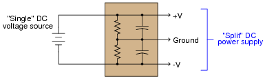
Design a passive circuit that will create a ßplit" (+V/-V) power supply from a single voltage source:

|
|
|
|
Follow-up question: what design constraints will dictate the sizes of the resistors and capacitors?
Notes:
This simple filtered voltage divider circuit works well when the current draws are low, or at least very close to being equal, on the +V and -V load rails. It does not work so well for highly asymmetrical loads, or where low quiescent current draw is important (low-power battery circuits, for example). In applications requiring better +V/-V voltage stability, an opamp "follower" circuit is recommended after the voltage divider.
Question 2:
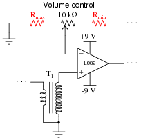
After experimenting some with this intercom circuit, you will find that there is a point on the volume control below which so little sound is reproduced that it is almost useless, and a point above which there is substantial distortion. Explain how you could place ßtops" to limit the volume control range so that the user could not adjust past these points, making the volume control more useful.
|
|
Notes:
This technique is frequently used to "bound" the range of a potentiometer within a pair of desired limits. For a circuit such as this, the only way to really determine where the upper and lower limits are is by experimenting.
Question 3:
Suppose a student builds this circuit and notices that it spontaneously breaks into oscillations, whether or not the "microphone" speaker is picking up any sound. Identify some possible causes of oscillation in a circuit like this, as well as possible fixes.
- �
- Insufficient power supply decoupling (add a large capacitor across the power supply terminals of the opamp.)
- �
- Stray capacitive coupling between input and output wiring (re-route wires, keeping input and output wiring well separated.)
- �
- Amplifier gain too high (add limiting resistor(s) to the opamp's feedback to prevent the gain adjustment from being set too high.)
- �
- Transformer phasing (reverse one winding of the transformer with respect to the other winding.)
Notes:
Unwanted oscillations in amplifier circuitry is a very real problem many electronics technicians and engineers alike must face. There is often no single correct solution to the problem, given the multiple avenues through which regenerative feedback may take place in a circuit.