Design Project: Audio tone control
Question 1:
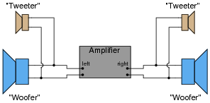
Suppose you were installing a high-power stereo system in your car, and you wanted to build a simple filter for the "tweeter" (high-frequency) speakers so that no bass (low-frequency) power is wasted in these speakers. Modify the schematic diagram below with a filter circuit of your choice:
|
|
Hint: this only requires a single component per tweeter!
|
|
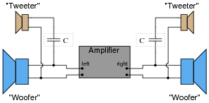
Follow-up question: what type of capacitor would you recommend using in this application (electrolytic, mylar, ceramic, etc.)? Why?
Notes:
Ask your students to describe what type of filter circuit a series-connected capacitor forms: low-pass, high-pass, band-pass, or band-stop? Discuss how the name of this filter should describe its intended function in the sound system.
Regarding the follow-up question, it is important for students to recognize the practical limitations of certain capacitor types. One thing is for sure, ordinary (polarized) electrolytic capacitors will not function properly in an application like this!
Question 2:
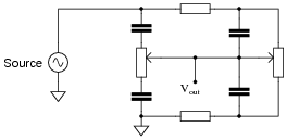
Examine the following schematic diagram for an audio tone control circuit:
|
|
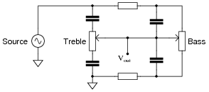
Determine which potentiometer controls the bass (low frequency) tones and which controls the treble (high frequency) tones, and explain how you made those determinations.
|
|
Notes:
The most important answer to this question is how your students arrived at the correct potentiometer identifications. If none of your students were able to figure out how to identify the potentiometers, give them this tip: use the superposition theorem to analyze the response of this circuit to both low-frequency signals and high-frequency signals. Assume that for bass tones the capacitors are opaque (Z = �) and that for treble tones they are transparent (Z = 0). The answers should be clear if they follow this technique.
This general problem-solving technique - analyzing two or more ëxtreme" scenarios to compare the results - is an important one for your students to become familiar with. It is extremely helpful in the analysis of filter circuits!
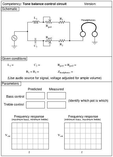
Question 3:
|
|
Note: when testing the frequency response of the tone control circuit, you may need to replace the headphones with a non-inductive resistor of equivalent impedance, and measure Vout across it.
Notes:
A good source of audio signal is the headphone output jack of almost any radio, media player, or other portable audio device. Students like being able to do a lab exercise that directly relates to technology they're already familiar with.
The higher-impedance the headphones are, the better this circuit works, since the combination of potentiometers and mixing resistors tends to result in a relatively high output impedance. I have used cheap headphones (32 ohm) with some success, given the following component values:
- �
- C1 = 0.1 mF
- �
- L1 = 200 mH (actually two 100 mH inductors in series)
- �
- R1 = R2 = 1 kW
- �
- Rpot1 = Rpot2 = 10 kW
Some students with limited hearing range have difficulty detecting the changes in tone using 10 kW potentiometers. You may wish to use 100 kW potentiometers instead for added attenuation. Operating such a circuit is akin to operating a water faucet with "hot" and "cold" water valves: the two settings together determine temperature and flow (tone and volume, respectively, for the metaphorically challenged).
An extension of this exercise is to incorporate troubleshooting questions. Whether using this exercise as a performance assessment or simply as a concept-building lab, you might want to follow up your students' results by asking them to predict the consequences of certain circuit faults.
If you plan to use this exercise as a troubleshooting assessment, I recommend against inducing the following component failures, as they are difficult to detect when the signal source is music rather than a constant tone of known frequency and amplitude:
- �
- Shorted capacitor (C1)
- �
- Shorted inductor (L1)
- �
- Shorted fixed-value resistors (R1 or R2)
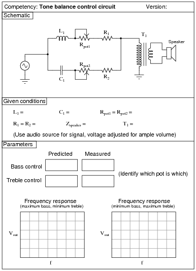
Question 4:
|
|
Note: when testing the frequency response of the tone control circuit, you may need to replace the transformer/speaker assembly with a non-inductive resistor of equivalent impedance, and measure Vout across it.
Notes:
A good source of audio signal is the headphone output jack of almost any radio, media player, or other portable audio device. Students like being able to do a lab exercise that directly relates to technology they're already familiar with.
I have experienced good success with the following component values:
- �
- C1 = 0.1 mF
- �
- L1 = 200 mH (actually two 100 mH inductors in series)
- �
- R1 = R2 = 1 kW
- �
- T1 = 1000:8 ohm audio output transformer
- �
- Rpot = Rpot2 = 10 kW
- �
- Speaker = small 8 W unit (salvaged from an old clock radio or other inexpensive audio device)
An extension of this exercise is to incorporate troubleshooting questions. Whether using this exercise as a performance assessment or simply as a concept-building lab, you might want to follow up your students' results by asking them to predict the consequences of certain circuit faults.