Time-delay electromechanical relays
Question 1:
What does the normal status of an electrical switch refer to? Specifically, what is the difference between a normally-open switch and a normally-closed switch?
Notes:
An important qualification for an electrical switch to be either "normally-open" or "normally-closed" is that it have a spring to return it to its "normal" state in the absence of an actuating force. Latching switches such as most toggle switches really cannot be defined in terms of "normally-" anything. Discuss this with your students, possibly showing them some examples of momentary contact switches that are either N.O. or N.C.
Question 2:
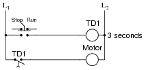
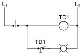
A special class of electromechanical relays called time-delay relays provide delayed action, either upon power-up or power-down, and are commonly denoted in ladder logic diagrams by "TD" or "TR" designations near the coil symbols and arrows on the contact symbols. Here is an example of a time-delay relay contact used in a motor control circuit:
|
|
In this circuit, the motor delays start-up until three seconds after the switch is thrown to the "Run" position, but will stop immediately when the switch is returned to the "Stop" position. The relay contact is referred to as normally-open, timed-closed, or NOTC. It is alternatively referred to as a normally-open, on-delay contact.
Explain how the arrow symbol indicates the nature of this contact's delay, that delay occurs during closure but not during opening.
Notes:
The arrow symbol is not difficult to figure out, but it is essential to know when working with time-delay relay circuits. Ask your students to describe their understanding of the arrow symbol as they answer this question.
Question 3:
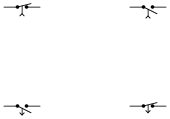
Match the following time-delay relay contact type symbols and labels:
|
|
- �
- Normally-open, timed-closed
- �
- Normally-open, timed-open
- �
- Normally-closed, timed-closed
- �
- Normally-closed, timed-open
|
|
Follow-up question: how do you make sense of the arrow in each contact symbol, with regard to whether the contact is timed-open or timed-closed?
Notes:
Ask your students to present their personal explanations of how to make sense of the arrow directions, in relation to whether the relay is "timed-open" or "timed-closed." The correlation is really not that complex, but it is a good thing to clearly elaborate on it for the benefit of the whole class. You may want to re-phrase the question like this: "Does the arrow represent the direction of timed motion or the direction of instantaneous motion?"
Question 4:
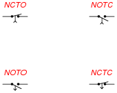
Match the following time-delay relay contact type symbols and labels:

|
|
- �
- Normally-open, on-delay
- �
- Normally-open, off-delay
- �
- Normally-closed, on-delay
- �
- Normally-closed, off-delay
|
|
Follow-up question: how do you make sense of the arrow in each contact symbol, with regard to whether the contact is an ön-delay" or an öff-delay"?
Notes:
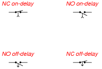
Ask your students to present their personal explanations of how to make sense of the arrow directions, in relation to whether the relay is an ön-delay" or an öff-delay." The correlation is really not that complex, but it is a good thing to clearly elaborate on it for the benefit of the whole class. You may want to re-phrase the question like this: Ïs it possible to determine whether each contact is on- or off-delay merely by looking at the arrow, or must one also consider the "normal" status?"
If some students believe this may be determined by arrow direction alone, show them these symbols:
|
|
Question 5:
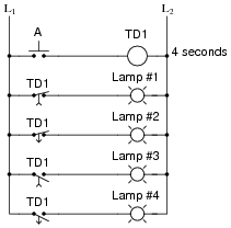
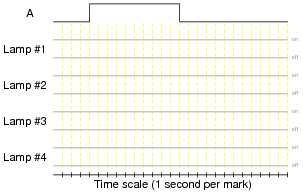
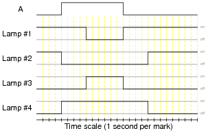
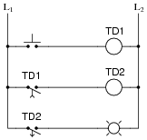
Time-delay relays are important circuit elements in many applications. Determine what each of the lamps will do in the following circuit when pushbutton Ä" is pressed for 10 seconds and then released:
|
|
Timing diagram:
|
|
|
|
Follow-up question: identify each relay contact by name:
- �
- Normally-closed, timed-open
- �
- Normally-open, timed-open
- �
- Normally-closed, timed-close
- �
- Normally-open, timed-close
Notes:
Time-delay relays are not the easiest for some students to understand. The purpose of this question is to introduce students to the four basic types of time-delay relay contacts and their respective behaviors. Discuss with your students how the contact symbols make sense (arrows on the switch actuators describing direction of delay).
Note to your students how it is possible to have different types of time-delay contacts actuated by the same relay coil.
Question 6:
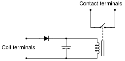
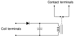
A simple time-delay relay may be constructed by connecting a large capacitor in parallel with the relay coil, like this:
|
|
Explain how this circuit works, and also determine what type of time-delay relay function is provided by it (NOTO, NOTC, NCTO, or NCTC).
Follow-up question: what purpose does the diode serve in this circuit?
Notes:
For substantial time delays (many seconds) on large relays (high-current coils), the capacitor must be huge, making this a somewhat impractical circuit for all but miniature relays.
Question 7:
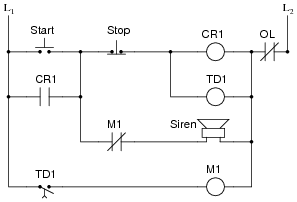
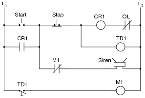
An electric motor is used to power a large conveyor belt. Before the motor actually starts, a warning siren activates to alert workers of the conveyor's forthcoming action. The following relay circuit accomplishes both tasks (motor control plus siren alert):
|
|
Study this ladder logic diagram, then explain how the system works.
Notes:
This circuit provides students an opportunity to analyze the workings of a delayed-start motor control circuit, where some other action (a siren in this case) takes place during the motor's delay. Have your students present both their analyses and the methods behind the analyses as you work through this question with them.
Question 8:
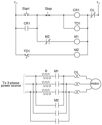
Large electric motors are often equipped with some form of soft-start control, which applies power gradually instead of all at once (as in äcross the line" starting). Here is an example of a simple ßoft start" control system:
|
|
Analyze this ladder logic diagram, and explain how it starts up the electric motor more gently than an äcross-the-line" starter would.
Notes:
After being accustomed to seeing resistors drawn as zig-zag symbols, it may take some students a few moments to realize the ßquare wave" components in the motor power diagram are actually resistors. Confusing? Yes, but this is the standard symbolism for ladder-logic diagrams!
Question 9:
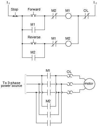
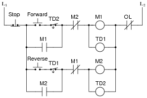
The following ladder logic diagram is for a reversing motor control circuit:
|
|
Study this diagram, then explain how motor reversal is accomplished. Also, identify the function of each "M" contact in the control circuit, especially those normally-closed contacts in series with the motor starter coils.
Now consider the following modification made to the reversing motor control circuit (motor and power contacts not shown here):
|
|
What extra functionality do the time-delay relays contribute to this motor control circuit?
Follow-up question: figure out how to simplify the time-delay relay circuit. Hint: integrate the time-delay and interlocking functions into a single contact (per rung).
Notes:
This circuit provides students an opportunity to analyze the workings of a delayed-start, reversing motor control circuit. Have your students present both their analyses and the methods behind the analyses as you work through this question with them.
Question 10:
An electric motor is used to power a large conveyor belt. Before the motor actually starts, a warning siren activates to alert workers of the conveyor's forthcoming action. The following relay circuit is supposed to accomplish both tasks (motor control plus siren alert):

|
|
Unfortunately, there is a problem somewhere in this circuit. Instead of activating the siren before starting the motor, there is silence. The motor's start is still delayed by the correct amount of time, but the siren never makes a sound. Identify some possible causes of this problem. Also, identify portions of the circuit you know to be functioning properly.
Possible faults:
- �
- Siren failed open
- �
- M1 contact (normally-closed) failed open
Things known to work:
- �
- Control relay CR1
- �
- Motor starter
- �
- Motor
Notes:
This circuit provides students an opportunity to analyze the workings of a delayed-start motor control circuit, where some other action (a siren in this case) takes place during the motor's delay. Have your students present both their analyses and the methods behind the analyses as you work through this question with them.
Question 11:
An electric motor is used to power a large conveyor belt. Before the motor actually starts, a warning siren activates to alert workers of the conveyor's forthcoming action. The following relay circuit accomplishes both tasks (motor control plus siren alert):
|
|
However, this circuit is poorly designed. Although it works just fine under normal conditions, it may not do what it should in the event of an overload heater trip (if the normally-closed ÖL" contact opens). Explain what is wrong with this circuit.
Notes:
This circuit provides students an opportunity to analyze the workings of a delayed-start motor control circuit, where some other action (a siren in this case) takes place during the motor's delay. Have your students present both their analyses and the methods behind the analyses as you work through this question with them.
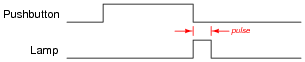
Question 12:
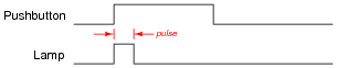
Suppose you needed to build a circuit that pulsed a lamp on and off (once) when a pushbutton is pressed and held. In other words, you wanted the lamp to do this:
|
|
Draw a ladder logic diagram for a circuit that would fulfill this function, using at least one time-delay relay.
|
|
Notes:
This is a good problem-solving exercise, figuring out how to creatively combine time-delay relays to perform a specific function.
Question 13:
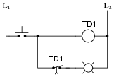
Suppose an engineer draws the following timing diagram for a time-delay relay circuit and then hands the diagram to a technician to figure out how to build it:

|
|
The technician, being well educated in the ways of time-delay relays, takes one look at this timing diagram and begins to laugh. Explain why this diagram is funny.
Notes:
The real purpose of this question is to get students to recognize an impossibility in timing diagrams. As an instructor, I see students mistakes such as this once in a while. Those students who have trouble answering this question may not yet fully understand how to interpret timing diagrams!
Question 14:
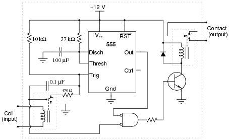
Determine what sort of time-delay relay this circuit is:
|
|
Also, calculate the amount of delay, in seconds. Hint: the 555's timing capacitor will charge from 0 volts to [2/3] supply voltage during the charging cycle.
Notes:
Some students may mistakenly base their time calculations on the 10 kW resistor and/or the 0.1 mF capacitor. Discuss the role of these two components in triggering the 555 timer, and how the time delay of the relay is actually set by the other R and C.
Question 15:
Explain what a time-delay relay is, and how it functionally differs from a regular electromechanical relay.
Notes:
The earliest time-delay relays used pneumatic "dash-pot" motion dampers to provide the necessary actuation or de-actuation delays. Modern time-delay relays use electronic timer circuits to do the time delay function, even when the output of the relay is still a set of mechanical contacts.
Question 16:
A simple time-delay relay may be constructed by connecting a large capacitor in parallel with the relay coil, like this:
|
|
Explain how this circuit works, and also determine what type of time-delay relay function is provided by it (NOTO, NOTC, NCTO, or NCTC).
Follow-up question: what purpose does the diode serve in this circuit?
Notes:
For substantial time delays (many seconds) on large relays (high-current coils), the capacitor must be huge, making this a somewhat impractical circuit for all but miniature relays.
Question 17:
Suppose you needed to build a circuit that pulsed a lamp on and off (once) when a pushbutton is released. In other words, you wanted the lamp to do this:
|
|
Draw a ladder logic diagram for a circuit that would fulfill this function, using at least one time-delay relay.
|
|
Notes:
This is a good problem-solving exercise, figuring out how to creatively combine time-delay relays to perform a specific function.
Question 18:
Suppose you needed to build a circuit that delayed the energization of a lamp when the button was pushed, and also delayed its turning off when the button was released. In other words, you wanted the lamp to do this:
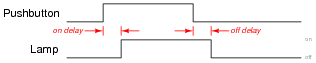
|
|
Draw a ladder logic diagram for a circuit that would fulfill this function, using at least one time-delay relay.
|
|
Follow-up question: which relay controls the on-delay time, and which relay controls the off-delay time?
Notes:
This is a good problem-solving exercise, figuring out how to creatively combine time-delay relays to perform a specific function.
Question 19:
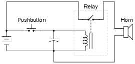
When the pushbutton is pressed, the relay immediately energizes and sends power to the electric horn. When the pushbutton is released, the horn remains on for a few moments before turning off, due to the capacitor's stored charge continuing to power the relay coil. So, the capacitor and relay form a time-delay control circuit for the horn:
|
|
Suppose this circuit has functioned as designed for quite some time, then one day develops a problem. The horn sounds immediately when the pushbutton is pressed (as it should), bit it immediately silences instead of continuing to sound for a few more moments when the pushbutton is released. Based on this information, identify these things:
- �
-
Two components or wires in the circuit that you know must be in good working condition.
- �
- Two components or wires in the circuit that could possibly be bad (and thus cause the off-delay action to fail).
Notes:
The purpose of this troubleshooting question is to get students to think in terms of fault elimination: deciding what things cannot be bad in order to better isolate what might be bad.