Resistors
Question 1:
Shown here is the schematic symbol for a resistor:

|
|
What is the purpose of a resistor? What function does it perform? Also, draw an illustration of what a real resistor looks like.

|
|
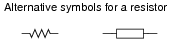
It is also good to know that the zig-zag symbol shown in the question is not the only symbol used to represent resistors. Another common resistor symbol is shown here:

|
|
Notes:
Students may (properly) ask, "Why is there such a thing as a component whose sole purpose is to impede the flow of electrons?" While resistors may seem rather pointless at first, they end up being extremely valuable electrical/electronic components. If asked, you may cite several uses of resistors in circuits:
- �
- To limit maximum circuit current to a safe value.
- �
- To ßplit" a voltage into proportions.
- �
- To ßcale" meter movements, for precise measurement of current and voltage.
- �
- To provide a non-shorting path to discharge static electricity.
Question 2:
Resistors are sometimes represented in electrical and electronic schematic diagrams by a symbol other than this:

|
|
Draw this other symbol next to the one shown above.
|
|
Notes:
It might be a good idea to occasionally draw schematic diagrams for your students using the öther" resistor symbol, just so they are not taken by surprise when they see this symbol in real schematics. Just be sure to remain consistent in your symbolism within each diagram: never mix the two different symbols within the same schematic!
Question 3:
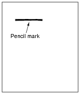
A primitive resistor may be formed by sketching a thick line on a piece of paper, using a pencil (not an ink pen!):
|
|
How may the end-to-end electrical resistance of this pencil mark be increased? How may it be decreased? Explain your answers.
Notes:
Creating a resistor on paper using a pencil is a very easy experiment to perform, the resistance of which may be measured with an ohmmeter. I strongly recommend this as a classroom exercise!
Question 4:
When a resistor conducts electric current, its temperature increases. Explain how this phenomenon is significant to the application of resistors in electric circuits. In other words, why would we care about a resistor's temperature increasing?
Also, what does this indicate about the technical ratings of resistors? Aside from having a specific resistance rating (i.e. a certain number of ohms), what other rating is important for proper selection of resistors in electric circuits?
Notes:
Students need to understand that resistance alone does not fully dictate the selection of a resistor for electrical service. Failure to heed the dissipation ratings of a resistor can result in catastrophic failure!
A good follow-up question to this is to ask what the unit of measurement is for this kind of thermal rating.
Question 5:
Many resistors have their electrical resistance shown by a set of color codes, or "bands," imprinted around their circumference. A standard color code associates each color with a specific decimal digit (0 through 9). Associate each of the following digits with its respective color:
- 0
- =
- 1
- =
- 2
- =
- 3
- =
- 4
- =
- 5
- =
- 6
- =
- 7
- =
- 8
- =
- 9
- =
- 0
- = Black
- 1
- = Brown
- 2
- = Red
- 3
- = Orange
- 4
- = Yellow
- 5
- = Green
- 6
- = Blue
- 7
- = Violet
- 8
- = Grey
- 9
- = White
Notes:
Several limericks have been invented to remember this color code, most of them "politically incorrect." I often challenge students to invent their own limericks for remembering this color code, and screen the inappropriate creations from general class discussion.
Question 6:
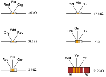
Observe the following "4-band" resistors, their color codes, and corresponding resistance values (note that the last color band is omitted, since it deals with precision and not nominal value):
|
|
What patterns do you notice between the color codes (given as three-letter abbreviations, so as to avoid interpretational errors resulting from variations in print quality), the resistance values, and the physical sizes of the resistors?
Follow-up question: what does the physical size of a resistor represent, if not resistance?
Notes:
The normal way to teach students the resistor color code is to show them the code first, then show them some resistors. Here, the sequence is reversed: show the students some resistors, and have them figure out the code. An important cognitive skill is the ability to detect and apply patterns in sets of data. Exercises such as this help build that skill.
Question 7:
What does the last color band represent on a color-coded resistor?
Notes:
This question is worded simply and directly enough that students might think there is only one right answer. However, upon doing some research they should find that there is more involved than one simple answer can encompass! Discuss with your students the different color code types, and what applications one might find resistors with "reliability" color codes in.
Regarding precision, nothing in life is perfectly accurate. However, the absence of perfect accuracy does not necessarily imply total uncertainty. In science, especially, it is important that all data be qualified by a statement of precision (or tolerance). Your students may be familiar with "margins of error" stated for public opinion polls. With resistors, this "margin of error" (expression of uncertainty) is explicitly given in the form of a separate color band.
Question 8:
Determine the nominal resistance values of these resistors, given their band colors, and also express the allowable tolerance in ohms.
For example, a 25 kW resistor with a 10% tolerance rating would have an allowable tolerance of +/- 2.5 kW.
- �
- Red, Org, Blu, Gld =
- �
- Brn, Blk, Grn, Sil =
- �
- Blu, Blk, Brn, Gld =
- �
- Yel, Vio, Red, Sil =
- �
- Grn, Brn, Yel =
- �
- Wht, Blu, Blk, Sil =
- �
- Gry, Grn, Org, Gld =
- �
- Org, Org, Gld =
- �
- Vio, Red, Sil, Gld =
- �
- Brn, Red, Blk, Sil =
- �
- Red, Org, Blu, Gld = 23 MW, +/- 1.15 MW
- �
- Brn, Blk, Grn, Sil = 1 MW, +/- 100 kW
- �
- Blu, Blk, Brn, Gld = 600 W, +/- 30 W
- �
- Yel, Vio, Red, Sil = 4.7 kW, +/- 470 W
- �
- Grn, Brn, Yel = 510 kW, +/- 102 kW
- �
- Wht, Blu, Blk, Sil = 96 W, +/- 9.6 W
- �
- Gry, Grn, Org, Gld = 85 kW, +/- 4.25 kW
- �
- Org, Org, Gld = 3.3 W, +/- 0.66 W
- �
- Vio, Red, Sil, Gld = 0.72 W, +/- 0.036 W
- �
- Brn, Red, Blk, Sil = 12 W, +/- 1.2 W
Notes:
This question serves as a great review for the mathematical concepts of scientific notation and percentages. Challenge your students to perform all the math without using a calculator, and without writing anything!
Question 9:
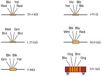
Observe the following "5-band" precision resistors, their color codes, and corresponding resistance values (note that the last color band is omitted, since it deals with precision and not nominal value):
|
|
What patterns do you notice between the color codes (given as three-letter abbreviations, so as to avoid interpretational errors resulting from variations in print quality) and the resistance values of each resistor? Why do precision resistors use a "5-band" color code instead of a "4-band" color code?
Notes:
The normal way to teach students the resistor color code is to show them the code first, then show them some resistors. Here, the sequence is reversed: show the students some resistors, and have them figure out the code. An important cognitive skill is the ability to detect and apply patterns in sets of data. Exercises such as this help build that skill.
It should be noted that there is a 5-band color code for non-precision resistors as well, with the first four bands serving the same purpose as in a 4-band code, the extra band indicating resistor reliability. This scheme was developed for military purposes and is seldom seen in civilian circuitry.
Question 10:
Determine whether or not the following resistors measure within the resistance range specified by their color codes:
- �
- (Org, Org, Red, Blk, Blu) Measured resistance = 332.5 W
- �
- (Brn, Blk, Blk, Gld, Red) Measured resistance = 9.7 W
- �
- (Blu, Vio, Brn, Red, Grn) Measured resistance = 67.43 kW
- �
- (Red, Wht, Grn, Yel, Vio) Measured resistance = 2.949 MW
- �
- (Yel, Vio, Org, Gld) Measured resistance = 44.68 kW
- �
- (Gry, Red, Brn, Sil) Measured resistance = 905 W
- �
- (Grn, Blu, Gld) Measured resistance = 6.73 W
- �
- (Vio, Brn, Red, Gld, Brn) Measured resistance = 70.82 W
- �
- (Wht, Org, Blu, Brn, Grn) Measured resistance = 9.38 kW
- �
- (Red, Blk, Wht, Grn, Vio) Measured resistance = 20.86 MW
Assume that all five-band resistors listed here use the precision color code as opposed to the military 5-band code where the fifth band indicates resistor reliability.
- �
- (Org, Org, Red, Blk, Blu) Measured resistance = 332.5 W Within tolerance
- �
- (Brn, Blk, Blk, Gld, Red) Measured resistance = 9.7 W Out of tolerance!
- �
- (Blu, Vio, Brn, Red, Grn) Measured resistance = 67.43 kW Within tolerance
- �
- (Red, Wht, Grn, Yel, Vio) Measured resistance = 2.949 MW Within tolerance
- �
- (Yel, Vio, Org, Gld) Measured resistance = 44.68 kW Within tolerance
- �
- (Gry, Red, Brn, Sil) Measured resistance = 905 W Out of tolerance!
- �
- (Grn, Blu, Gld) Measured resistance = 6.73 W Out of tolerance!
- �
- (Vio, Brn, Red, Gld, Brn) Measured resistance = 70.82 W Within tolerance
- �
- (Wht, Org, Blu, Brn, Grn) Measured resistance = 9.38 kW Within tolerance
- �
- (Red, Blk, Wht, Grn, Vio) Measured resistance = 20.86 MW Out of tolerance!
Notes:
This question serves as a great review for the mathematical concepts of scientific notation and percentages. They will have to calculate the allowable range of resistance values for each resistor in order to determine whether or not the measured value falls within that range.
Question 11:
Find one or two real resistors and bring them with you to class for discussion. Identify as much information as you can about your resistors prior to discussion:
- �
- Resistance (ideal)
- �
- Resistance (actual)
- �
- Power rating
- �
- Type (carbon composition, metal film, wire-wound, etc.)
Be prepared to prove the actual resistance of your resistors in class, by using a multimeter!
Notes:
The purpose of this question is to get students to kinesthetically interact with the subject matter. It may seem silly to have students engage in a ßhow and tell" exercise, but I have found that activities such as this greatly help some students. For those learners who are kinesthetic in nature, it is a great help to actually touch real components while they're learning about their function. Of course, this question also provides an excellent opportunity for them to practice interpreting color codes and/or component markings, use a multimeter, access datasheets, etc.