Shift registers
Question 1:
| Don't just sit there! Build something!! |
Learning to analyze digital circuits requires much study and practice. Typically, students practice by working through lots of sample problems and checking their answers against those provided by the textbook or the instructor. While this is good, there is a much better way.
You will learn much more by actually building and analyzing real circuits, letting your test equipment provide the änswers" instead of a book or another person. For successful circuit-building exercises, follow these steps:
- 1.
- Draw the schematic diagram for the digital circuit to be analyzed.
- 2.
- Carefully build this circuit on a breadboard or other convenient medium.
- 3.
- Check the accuracy of the circuit's construction, following each wire to each connection point, and verifying these elements one-by-one on the diagram.
- 4.
- Analyze the circuit, determining all output logic states for given input conditions.
- 5.
- Carefully measure those logic states, to verify the accuracy of your analysis.
- 6.
- If there are any errors, carefully check your circuit's construction against the diagram, then carefully re-analyze the circuit and re-measure.
Always be sure that the power supply voltage levels are within specification for the logic circuits you plan to use. If TTL, the power supply must be a 5-volt regulated supply, adjusted to a value as close to 5.0 volts DC as possible.
One way you can save time and reduce the possibility of error is to begin with a very simple circuit and incrementally add components to increase its complexity after each analysis, rather than building a whole new circuit for each practice problem. Another time-saving technique is to re-use the same components in a variety of different circuit configurations. This way, you won't have to measure any component's value more than once.
Notes:
It has been my experience that students require much practice with circuit analysis to become proficient. To this end, instructors usually provide their students with lots of practice problems to work through, and provide answers for students to check their work against. While this approach makes students proficient in circuit theory, it fails to fully educate them.
Students don't just need mathematical practice. They also need real, hands-on practice building circuits and using test equipment. So, I suggest the following alternative approach: students should build their own "practice problems" with real components, and try to predict the various logic states. This way, the digital theory "comes alive," and students gain practical proficiency they wouldn't gain merely by solving Boolean equations or simplifying Karnaugh maps.
Another reason for following this method of practice is to teach students scientific method: the process of testing a hypothesis (in this case, logic state predictions) by performing a real experiment. Students will also develop real troubleshooting skills as they occasionally make circuit construction errors.
Spend a few moments of time with your class to review some of the "rules" for building circuits before they begin. Discuss these issues with your students in the same Socratic manner you would normally discuss the worksheet questions, rather than simply telling them what they should and should not do. I never cease to be amazed at how poorly students grasp instructions when presented in a typical lecture (instructor monologue) format!
I highly recommend CMOS logic circuitry for at-home experiments, where students may not have access to a 5-volt regulated power supply. Modern CMOS circuitry is far more rugged with regard to static discharge than the first CMOS circuits, so fears of students harming these devices by not having a "proper" laboratory set up at home are largely unfounded.
A note to those instructors who may complain about the "wasted" time required to have students build real circuits instead of just mathematically analyzing theoretical circuits:
What is the purpose of students taking your course?
If your students will be working with real circuits, then they should learn on real circuits whenever possible. If your goal is to educate theoretical physicists, then stick with abstract analysis, by all means! But most of us plan for our students to do something in the real world with the education we give them. The "wasted" time spent building real circuits will pay huge dividends when it comes time for them to apply their knowledge to practical problems.
Furthermore, having students build their own practice problems teaches them how to perform primary research, thus empowering them to continue their electrical/electronics education autonomously.
In most sciences, realistic experiments are much more difficult and expensive to set up than electrical circuits. Nuclear physics, biology, geology, and chemistry professors would just love to be able to have their students apply advanced mathematics to real experiments posing no safety hazard and costing less than a textbook. They can't, but you can. Exploit the convenience inherent to your science, and get those students of yours practicing their math on lots of real circuits!
Question 2:
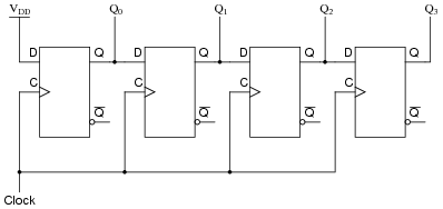
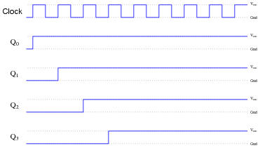
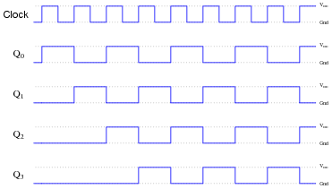
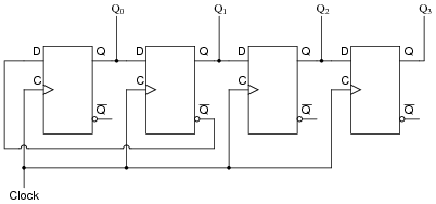
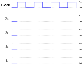
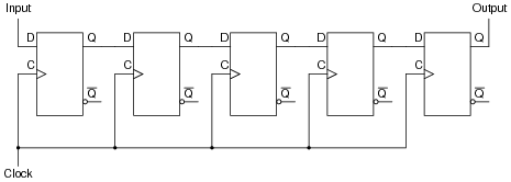
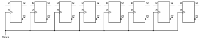
Complete the timing diagram for this circuit, assuming all Q outputs begin in the low state:
|
|

|
|
|
|
Follow-up question: explain why the "high" state at the D input of the first flip-flop does not ripple through all the flip-flops at the first clock pulse.
Notes:
This question reviews the principles of D-type flip-flops, timing diagrams, and serves as an introduction to shift registers.
Question 3:
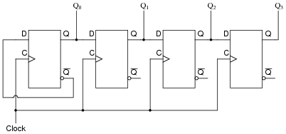
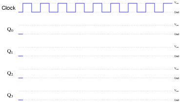
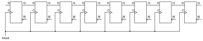
Complete the timing diagram for this circuit, assuming all Q outputs begin in the low state:
|
|
|
|
|
|
Notes:
This question reviews the principles of D-type flip-flops, timing diagrams, and serves as an introduction to shift registers.
Question 4:
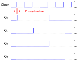
Complete the timing diagram for this circuit, showing propagation delays for all flip-flops (delay times much less than the width of a clock pulse), assuming all Q outputs begin in the low state:
|
|
|
|
|
|
Notes:
This question reviews the principles of D-type flip-flops, timing diagrams, and serves as an introduction to shift registers.
Question 5:
What is the definition of a register in the context of digital circuitry? Also, define and compare/contrast what a shift register is.
Notes:
Registers are a good way to introduce the basic concepts of solid-state (RAM) memory technology, showing how flip-flop or latch circuits may be used as data storage devices. Be sure to ask your students where they were able to find this information, as it should be very easy for them to research!
Question 6:
Explain the difference between serial digital data and parallel digital data.
Notes:
Ask your students of they have ever heard of ßerial" and "parallel" ports on personal computers. If time permits, have them examine the two types of ports on the back of a PC, contrasting the number of pins used for each connector.
Question 7:
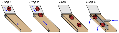
A helpful analogy for a shift register is a conveyor belt. Examine this illustration showing a single conveyor belt at four different times, and determine which of the following shift register operations the sequence represents:
- �
- Parallel-in, serial-out
- �
- Parallel-in, parallel-out
- �
- Serial-in, serial-out
- �
- Serial-in, parallel-out
|
|
Notes:
Some analogies can be very helpful to students as they learn new concepts. I have found that conveyor belts work very well to illustrate the different types of shift register behaviors.
Question 8:
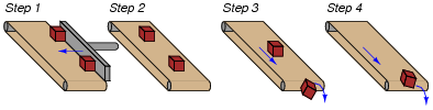
A helpful analogy for a shift register is a conveyor belt. Examine this illustration showing a single conveyor belt at four different times, and determine which of the following shift register operations the sequence represents:
- �
- Parallel-in, serial-out
- �
- Parallel-in, parallel-out
- �
- Serial-in, serial-out
- �
- Serial-in, parallel-out
|
|
Notes:
Some analogies can be very helpful to students as they learn new concepts. I have found that conveyor belts work very well to illustrate the different types of shift register behaviors.
Question 9:
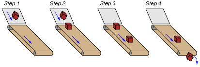
A helpful analogy for a shift register is a conveyor belt. Examine this illustration showing a single conveyor belt at four different times, and determine which of the following shift register operations the sequence represents:
- �
- Parallel-in, serial-out
- �
- Parallel-in, parallel-out
- �
- Serial-in, serial-out
- �
- Serial-in, parallel-out
|
|
Notes:
Some analogies can be very helpful to students as they learn new concepts. I have found that conveyor belts work very well to illustrate the different types of shift register behaviors.
Question 10:
Draw the schematic diagram for a five-bit serial-in/serial-out shift register circuit, and be prepared to give a brief explanation of how it functions.
|
|
Follow-up question: if we wished to output data from this shift register circuit in parallel form, where would we make the connections?
Notes:
One application for a serial-in/serial-out shift register is a precise time delay for serial-stream data.
Question 11:
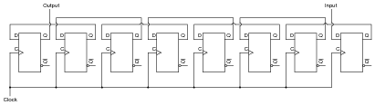
Draw the necessary connecting wires between flip-flops so that serial data is shifted from right to left instead of left to right as you may be accustomed to seeing in a shift register schematic:
|
|
Be sure to also note where data enters this shift register, and where data exits.
|
|
Notes:
This is a very simple question to answer. I present it here primarily so that students start thinking about how to change the direction of shift in a shift register circuit: a prelude to bidirectional shift register circuits.
Question 12:
Explain how a shift register circuit could be built from D-type flip-flops with the ability to shift data either to the right or to the left, on command. I'm not necessarily asking for a schematic diagram so much as I'm looking for an explanation of how such a circuit might be built. Of course, if your best way of presenting your idea is to draw a schematic diagram, go ahead!
Notes:
I purposely avoided asking a question about schematics for a reason: it is too easy to simply look through a textbook or research a datasheet and copy a drawing. What is most important here is that students comprehend how bidirectionality is achieved in shift register circuits. What, exactly, is a steering gate, why are they used, and what in/out flip-flop connections are needed to achieve a desired shift direction.
Question 13:
Explain what a universal shift register is. The 74194 is an example of a TTL universal shift register, so you will find that datasheet very helpful in answering this question.
Note: this answer is purposely minimal. I expect you to provide a more detailed answer during discussion, based on research of universal shift registers!
Notes:
Regarding the point in the answer about student research, ask your students how a single shift register chip is able to perform all the different types of input/output combinations. Ask your students, for instance, how to make the 74194 act only as a parallel-in/parallel-out register.
Question 14:
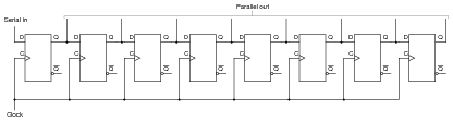
An important function in computer circuitry is serial-to-parallel data conversion, where a stream of serial data is "read" one bit at a time, then all bits output at once in parallel form. A shift register circuit is ideal for this application. Shown here is an eight-bit shift register circuit:
|
|
Draw any necessary wires and labels showing where serial data would enter the circuit, and where parallel data would exit.
|
|
Follow-up question: if we were to actually use this circuit for serial-to-parallel data conversion, we would have to be careful how fast we clocked the shift register. Explain why.
Notes:
The subject of serial-to-parallel data conversion is much deeper than what is suggested by this disarmingly simple circuit. Talk with your students about the need for clock synchronization (even in äsynchronous" serial data transmission).
Question 15:
Suppose we wished to use a shift register circuit to input several binary bits at once (parallel data transfer), and then output the bits one at a time over a single line (serial data transfer). You should be aware of how shift registers are constructed with D-type flip-flops. Now, describe how we can get parallel data entered into a shift register circuit. Note: there is more than one answer to this question!
Notes:
During discussion, have your students draw a picture of a parallel-in/serial-out shift register circuit, or at least cite a page number reference in their textbook, so you may be sure they understand what they're talking about (and not just repeating the given answer).
Question 16:
A binary number is parallel-loaded into a shift register. The shift register is then commanded to ßhift right" for one clock pulse. How does the value of the shifted binary number compare to the number originally loaded in, assuming that the MSB is on the very left flip-flop of the shift register?
Follow-up question: how could we use the shift register to double the value of a binary number?
Challenge question: when we divide a binary number in two by shifting its bit positions, the resulting answer may or may not be exactly one-half the original value. Explain why this is so. Also, analyze what happens when when we multiply a binary number by two through a process of bit-shifting. Is the resulting answer exactly twice the original value, or may it also be approximate as it sometimes is with division? Explain why or why not.
Notes:
This is a really neat trick for dividing or multiplying binary numbers by powers of two. It is often used in machine-language microprocessor programming, due to its simplicity of execution.
Question 17:
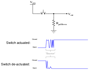
Switch contact bounce is often a problem when connecting mechanical contact switches or relays to the inputs of digital semiconductor circuits. When a switch transitions from open to closed, or from closed to open, there is usually a burst of on/off pulses rather than a single, crisp, change of logic state:
|
|
Digital electronic circuits, of course, react to these pulses as though they were very rapid actuations/de-actuations of the switch. This may cause problems, especially in applications where a mechanical switch input causes a counter to increment or decrement!
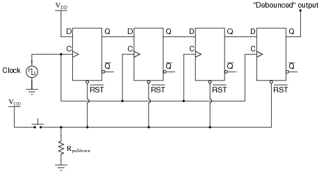
To fix this problem we must properly condition the switch signal to eliminate the spurious on/off pulses. The process of doing this is called debouncing. There is more than one way to de-bounce a switch, but one of the more sophisticated ways uses a serial-in, serial-out shift register with an asynchronous reset (clear) input:
|
|
Explain how this circuit works to de-bounce the switch's "dirty" signal, producing a "clean" (de-bounced) signal for a subsequent digital circuit's input.
Follow-up question #1: which switch (input) transition is seen immediately at the output, a low-to-high transition or a high-to-low transition?
Follow-up question #2: does this circuit de-bounce a noisy low-to-high switch (input) transition, a noisy high-to-low switch transition, or both?
Follow-up question #3: does the pushbutton switch source or sink current in this circuit?
Challenge question: how would you go about selecting an appropriate clock frequency for this circuit?
Notes:
Some students may need to see a pulse diagram for this circuit before they fully grasp how it functions. If so, have students come up to the board in the front of the room and work through an analysis of it rather than doing it yourself.
Not only does this question review shift register operation, but it also reviews the problem of switch contact bounce and showcases a practical solution for it. Incidentally, this question provides a good excuse for a hands-on demonstration of switch bounce using the switch/pulldown circuit first shown and a digital storage oscilloscope to capture the switching action. Students are likely to be surprised by just how "dirty" the switch signal is!
Question 18:
A mechanically inclined friend of yours wishes to build an automated water fountain, where ten water jets are turned on in sequence, one at a time. Each water jet is controlled by a solenoid valve, energized by 120 volt AC line power.
Your friend understands how to wire up the solenoid valves and build all the plumbing to make the fountain work. He also understands how to interpose power to the solenoid valve coils using small relays, so a digital control circuit operating at a low DC supply voltage will be able to energize the valves. The only problem is, this friend of yours does not know how to build a circuit to do the sequencing. How do you turn on one out of ten outputs at a time, in sequence?
Another friend who is studying digital circuits has a solution to the design problem. She says you could generate a one-out-ten sequence by using a BCD counter (4 bit) driving a 4-line to 16-line decoder. A simple 555 astable multivibrator circuit could supply the necessary clock pulses, and the decoder outputs could drive the relays, and then the solenoid valves, as fast as you wanted.
However, your instructor just recently told you about a different way to generate a one-out-of-n counting sequence by using shift registers: the circuit is called a ring counter. A ring counter would use fewer parts than the counter/decoder idea. Explain what a ring counter is, and how it would work in this application.
Notes:
Actually, this question would make a great class project for your students to build. Not just the ring counter itself, but all the power supply and power control circuitry as well. I've actually had a student team build a programmable ornamental fountain before, using a microcontroller. We entered it as a piece of kinetic artwork in a campus art show, and it was a hit (especially for young children playing in the water jets on a hot day). It was a lot of fun and the students learned a lot!
Question 19:
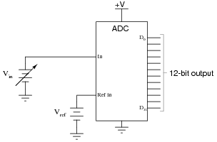
An analog-to-digital converter is a circuit that inputs an analog signal and outputs a multiple-bit binary number equivalent to that signal's amplitude:
|
|
A free-running analog-to-digital converter is one that updates its digital output as often as it can, not waiting for any prompting from another device. If we were to connect a free-running ADC to a computer (microprocessor or microcontroller), we would need some way to sample the ADC's output at times specified by the computer, and hold that binary number long enough for the computer to register it. Otherwise, the ADC may update its output in the middle of one of the computer's ïnput" cycles, possibly resulting in corrupted data.
We could build such a sample-and-hold circuit out of flip-flops. What type of flip-flop would we use for this purpose, and how many would we need for the ADC circuit shown above? This circuit we would build is also known as a shift register. What kind of shift register inputs multiple bits of data all at once, and transfers that data to its output lines all at once, at the command of a clock pulse?
Notes:
This type of shift register is immensely useful for sample-and-hold applications such as this.
Question 20:
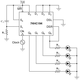
This shift register circuit energizes one LED at a time (beginning with the bottom LED at power-up), in a rotating pattern that moves at the pace of the clock:
|
|
A technician decides to reverse the direction of pattern motion, and alters the circuit as such:
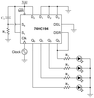
|
|
Unfortunately, this does not work as planned. Now, the bottom LED blinks once upon power-up, then all LEDs remain off. What did the technician do that was incorrect? What needs to be done to fix the problem?
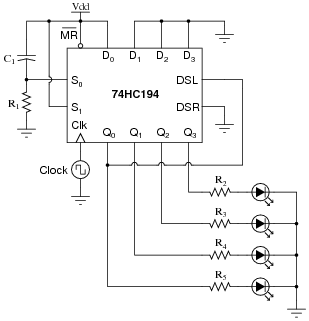
|
|
I will leave it to you to explain why this modification works!
Notes:
Students will probably need to consult a datasheet for the 74HC194 in order to figure out what is going on here. If they have not taken the initiative to do so, encourage them to both now and later! Datasheets are an invaluable source of information when it comes to integrated circuit behavior and the conditions necessary to make them do what you want them to do.
Question 21:
This shift register circuit produces a sequential light pattern reminiscent of the old Mercury Cougar tail-lights: first one LED energizes, then two LEDs energize, and then all three LEDs energize before all de-energizing and repeating the sequence. The 74HC194 shift register circuit is set to always operate in the ßhift right" mode with the shift-right serial input (DSR) tied high, the master reset ([`MR]) input used to set all output lines to a low state at the end of each cycle:
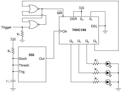
|
|
The sequential light pattern is supposed to begin whenever the "Trigger" input momentarily goes high. Unfortunately, something has failed in this circuit which is preventing any of the LEDs to come on. No blinking light sequence ensues, no matter what the state of the "Trigger" input.
Identify some likely failures in this circuit that could cause this to happen, other than a lack of power supply voltage. Explain why each of your proposed faults would cause the problem, and also identify how you would isolate each fault using test equipment.
These are not the only possible failures. Identify a few more on your own!
Notes:
Students will find a datasheet for the 74HC194 helpful in figuring out how this circuit is supposed to work.
Question 22:
This shift register circuit drives the four coils of a unipolar stepper motor, one at a time, in a rotating pattern that moves at the pace of the clock. The drive transistor circuitry (Q1, Q2, and resistors R2 through R6) are shown only for one of the four coils. The other three shift register outputs have identical drive circuits connected to the respective motor coils:
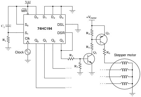
|
|
Suppose this stepper motor circuit worked just fine for several years, then suddenly stopped working. Explain where you would take your first few measurements to isolate the problem, and why you would measure there.
Notes:
This is a good question to discuss with your students, as it helps them understand how to "divide and conquer" a malfunctioning system.