Sum-of-Products and Product-of-Sums expressions
Question 1:
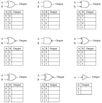
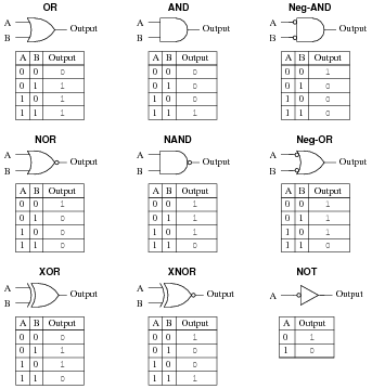
Identify each of these logic gates by name, and complete their respective truth tables:
Reveal Answer
Notes:
In order to familiarize students with the standard logic gate types, I like to given them practice with identification and truth tables each day. Students need to be able to recognize these logic gate types at a glance, or else they will have difficulty analyzing circuits that use them.
Hide Answer
Question 2:
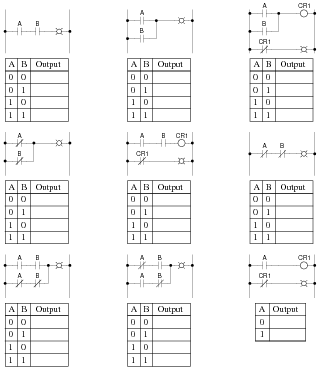
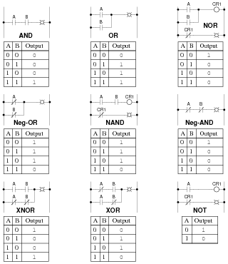
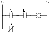
Identify each of these relay logic functions by name (AND, OR, NOR, etc.) and complete their respective truth tables:
Reveal Answer
Notes:
In order to familiarize students with standard switch contact configurations, I like to given them practice with identification and truth tables each day. Students need to be able to recognize these ladder logic sub-circuits at a glance, or else they will have difficulty analyzing more complex relay circuits that use them.
Hide Answer
Question 3:
Inspect each of these Boolean expressions, and determine whether each one is a
sum of products, or a
product of sums:
|
(X +
|
Y
|
+
|
Z
|
)(
|
Y
|
+ Z)(
|
X
|
+ Y)
|
|
Reveal Answer
|
(X +
|
Y
|
+
|
Z
|
)(
|
Y
|
+ Z)(
|
X
|
+ Y) POS |
|
The last two expressions are "trick" questions: while technically being the product of summed variables, and the sum of multiplied (product) variables, respectively, do not follow ßtandard" POS and SOP forms, because they both have long complementation bars:
For an expression to properly follow the SOP or POS canonical form, no complementation bar should cover more than one variable!
Notes:
Even if your students have never heard of Boolean algebra before, they should still be able to determine which of the first four expressions are SOP and which are POS. If there is any confusion on this point, ask your students to define what ßum" and "product" mean, respectively, and then discuss what it means for an expression to be a product (singular) of sums (multiple), or a sum (singular) of products (multiple).
Hide Answer
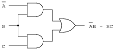
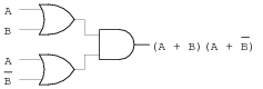
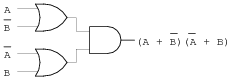
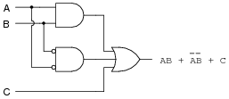
Question 4:
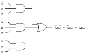
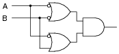
Sum-of-Product Boolean expressions all follow the same general form. As such, their equivalent logic gate circuits likewise follow a common form. Translate each of these SOP expressions into its equivalent logic gate circuit:
Reveal Answer
Notes:
The translation from Boolean SOP to gate circuit should not be difficult. The point of this question is to get students thinking in terms of sum-of-products form, so they will be ready for the next step: linking this concept with truth tables.
Hide Answer
Question 5:
Although it is seldom done, it is possible to express a truth table in verbal form, by describing what conditions must be met in order to generate a "high" output.
Take for example this simple truth table, for an inverter circuit:
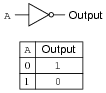
For this truth table, we could say that the output goes high when A is low. A different way of saying this would be to state that "the output is
true when [
`A] is
true."
Let's look at another example, this time of an AND gate:
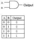
For this truth table, we could say that the output goes high when A and B are both high. A different way of saying this would be to state that "the output is true when A is true and B is true." To use a half-Boolean, half-verbal description:
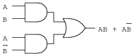
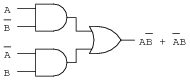
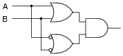
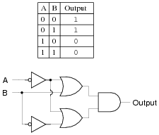
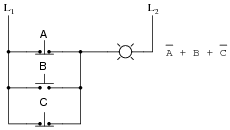
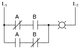
Examine this logic gate circuit and corresponding truth table:
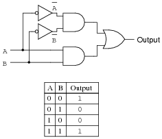
Express the functionality of this truth table in words. What Boolean conditions must be satisfied ("true") in order for the output to assume a high state?
Reveal Answer
The output of this circuit is high when [
`A] is true and [
`B] is true, or when A is true and B is true:
Notes:
Expressing truth table conditions "verbally" is a way to introduce students to the concept of deriving Boolean expression from them.
Hide Answer
Question 6:
Develop a verbal description of this truth table, specifying what conditions must be met ("
true" in a Boolean sense) in order for the output to assume a high state:
-
|
|
A
|
B
|
C
|
Output
|
|
|
0
|
0
|
0
|
0
|
|
|
0
|
0
|
1
|
0
|
|
|
0
|
1
|
0
|
0
|
|
|
0
|
1
|
1
|
0
|
|
|
1
|
0
|
0
|
0
|
|
|
1
|
0
|
1
|
1
|
|
|
1
|
1
|
0
|
0
|
|
|
1
|
1
|
1
|
0
|
|
|
Do the same for this truth table as well:
-
|
|
A
|
B
|
C
|
Output
|
|
|
0
|
0
|
0
|
0
|
|
|
0
|
0
|
1
|
1
|
|
|
0
|
1
|
0
|
1
|
|
|
0
|
1
|
1
|
0
|
|
|
1
|
0
|
0
|
0
|
|
|
1
|
0
|
1
|
0
|
|
|
1
|
1
|
0
|
0
|
|
|
1
|
1
|
1
|
0
|
|
|
Reveal Answer
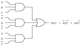
For the first truth table: the output of this circuit is high when A is true and [
`B] is true and C is true:
For the second truth table: the output of this circuit is high when [
`A] is true and [
`B] is true and C is true, or when [
`A] is true and B is true and [
`C] is true:
|
(
|
A
|
AND |
B
|
AND C) OR (
|
A
|
AND B AND |
C
|
)
|
|
Follow-up question: do you suspect we could write a formal Boolean expression for each of these truth tables? What would those expressions be, and what form would they be in (SOP or POS)?
Notes:
I find this "verbal" approach works well to introduce students to the concept of deriving Boolean expressions from truth tables.
Be sure to ask your students what Boolean expressions they derived for both these truth tables. Given the answers in "verbal" form, this should not be difficult for them!
Hide Answer
Question 7:
Suppose you were faced with the task of writing a Boolean expression for a logic circuit, the internals of which are unknown to you. The circuit has four inputs - each one set by the position of its own micro-switch - and one output. By experimenting with all the possible input switch combinations, and using a logic probe to "read" the output state (at test point TP1), you were able to write the following truth table describing the circuit's behavior:
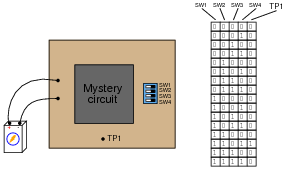
Based on this truth table "description" of the circuit, write an appropriate Boolean expression for this circuit.
Reveal Answer
To make things easier, I'll associate each of the switches with a unique alphabetical letter:
-
�
-
SW1 = A
-
�
- SW2 = B
-
�
- SW3 = C
-
�
- SW4 = D
Now, the Boolean expression:
Notes:
This problem gives students a preview of sum-of-products notation. By examining the truth table, they should be able to determine that only one combination of switch settings (Boolean values) provides a "1" output, and with a little thought they should be able to piece together this Boolean product statement.
Though this question may be advanced for some students (especially those weak in mathematical reasoning skills), it is educational for all in the context of classroom discussion, where the thoughts of students and instructor alike are exposed.
Hide Answer
Question 8:
Write a Boolean SOP expression for this truth table, then simplify that expression as much as possible, and draw a logic gate circuit equivalent to that simplified expression:
-
|
|
A
|
B
|
C
|
Output
|
|
|
0
|
0
|
0
|
0
|
|
|
0
|
0
|
1
|
0
|
|
|
0
|
1
|
0
|
1
|
|
|
0
|
1
|
1
|
0
|
|
|
1
|
0
|
0
|
0
|
|
|
1
|
0
|
1
|
0
|
|
|
1
|
1
|
0
|
1
|
|
|
1
|
1
|
1
|
0
|
|
|
Reveal Answer
Original SOP expression:
Simplified expression and gate circuit:

Notes:
Challenge your students to implement the original SOP expression directly with logic gates (three-input gates are acceptable to use).
Hide Answer
Question 9:
Write an SOP expression for this truth table, and then draw a gate circuit diagram corresponding to that SOP expression:
-
|
|
A
|
B
|
C
|
Output
|
|
|
0
|
0
|
0
|
0
|
|
|
0
|
0
|
1
|
0
|
|
|
0
|
1
|
0
|
1
|
|
|
0
|
1
|
1
|
1
|
|
|
1
|
0
|
0
|
0
|
|
|
1
|
0
|
1
|
0
|
|
|
1
|
1
|
0
|
0
|
|
|
1
|
1
|
1
|
1
|
|
|
Finally, simplify this expression using Boolean algebra, and draw a simplified gate circuit based on this new (reduced) Boolean expression.
Reveal Answer
Original SOP expression and gate circuit:
Reduced expression and gate circuit:
Notes:
Discuss with your students the utility of Boolean algebra as a circuit simplification tool. Ask your students to compare the original and reduced logic gate circuits, and comment on such performance metrics as reliability, power consumption, maximum operating speed, etc.
Hide Answer
Question 10:
Write an SOP expression for this truth table, and then draw a ladder logic (relay) circuit diagram corresponding to that SOP expression:
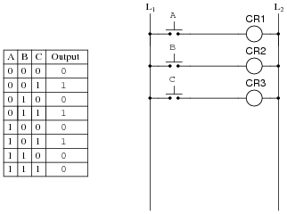
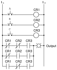
Implement the SOP logic function using contacts of relays CR1, CR2, and CR3. A partial ladder logic diagram has been provided for you.
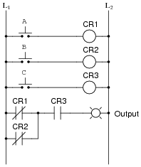
Finally, simplify this expression using Boolean algebra, and draw a simplified ladder logic diagram based on this new (reduced) Boolean expression. When deciding "how far" to reduce the Boolean expression, choose a form that results in the minimum number of relay contacts in the simplified ladder logic diagram.
Reveal Answer
Original SOP expression and relay circuit:
Reduced expression and relay circuit:
Notes:
Discuss with your students the utility of Boolean algebra as a circuit simplification tool. Ask your students to compare the original and reduced logic gate circuits, and comment on such performance metrics as reliability, power consumption, maximum operating speed, etc.
Hide Answer
Question 11:
Design the simplest relay circuit possible (i.e. having the fewest contacts) to implement the following truth table:
-
|
|
A
|
B
|
C
|
Output
|
|
|
0
|
0
|
0
|
0
|
|
|
0
|
0
|
1
|
0
|
|
|
0
|
1
|
0
|
1
|
|
|
0
|
1
|
1
|
0
|
|
|
1
|
0
|
0
|
0
|
|
|
1
|
0
|
1
|
0
|
|
|
1
|
1
|
0
|
1
|
|
|
1
|
1
|
1
|
1
|
|
|
Reveal Answer
Simplest relay circuit possible:
Notes:
Ask your students to show all their work in designing the relay circuit. By presenting their thought processes, not only do you help them consolidate their learning, but you also help the other students understand better by allowing them to learn from a peer.
Hide Answer
Question 12:
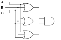
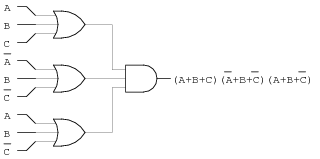
Product-of-Sum Boolean expressions all follow the same general form. As such, their equivalent logic gate circuits likewise follow a common form. Translate each of these POS expressions into its equivalent logic gate circuit:
|
(A + B + C)(
|
A
|
+ B +
|
C
|
)(A + B +
|
C
|
)
|
|
Reveal Answer
Notes:
The translation from Boolean POS to gate circuit should not be difficult. The point of this question is to get students thinking in terms of product-of-sums form, so they will be ready for the next step: linking this concept with truth tables.
Hide Answer
Question 13:
Product-of-Sum Boolean expressions all follow the same general form. As such, their equivalent logic gate circuits likewise follow a common form. Translate each of these POS expressions into its equivalent logic gate circuit:
|
(A + B + C)(
|
A
|
+ B +
|
C
|
)(A + B +
|
C
|
)
|
|
Reveal Answer
Notes:
The translation from Boolean POS to gate circuit should not be difficult. The point of this question is to get students thinking in terms of sum-of-products form, so they will be ready for the next step: linking this concept with truth tables.
Hide Answer
Question 14:
In an SOP expression, the minimum requirement for the expression's total value to be equal to 1 is that at least one of the product terms must be equal to 1. For instance, in the following SOP expression, we know that the value will be equal to 1 if ABC = 1 or if A[
`B] [
`C] = 1 or if AB[
`C] = 1:
What is the minimum requirement for a POS expression to be equal to 0? Take the following POS expression, for instance:
|
(A + B + C)(A +
|
B
|
+ C)(
|
A
|
+ B + C)
|
|
At the very least, what has to occur in order for this expression to equal 0?
Reveal Answer
At least one of the sum terms must be equal to zero.
Follow-up question: in order for one of these terms to be equal to zero, thus making the whole expression equal to zero, what must be true about each of the Boolean literals (a
literal is either a variable or the complement of a variable) within at least one of the sum terms?
Notes:
This question foreshadows the derivation of POS expressions from truth tables. It also parallels the subject of polynomial roots in real-number algebra. For instance, the polynomial x2 - 2x - 8 may be factored as such:
If we were to set this equation equal to zero, the
roots of the equation would be 4 and -2: the values for x which would make either one of the terms equal to zero.
You may find this mini-review of "normal" algebra to be helpful to your students, as they try to understand POS expressions.
Hide Answer
Question 15:
Examine the following truth table:

We know that this table represents the function of a NAND gate. But suppose we wished to generate a Boolean expression for this gate as though we didn't know what it already was, and we chose to generate an SOP expression based on all the "high" output conditions in the truth table:
Seems like a lot of work for just one gate, doesn't it? The fact that this truth table's output is mostly 1's causes us to have to write a relatively lengthy SOP expression. Wouldn't it be easier if we had a technique to generate a Boolean expression from the single
zero output condition in this table? If we had such a technique, our resulting Boolean expression would have a lot fewer terms in it!
We know that a Negative-OR gate has the exact same functionality as a NAND gate. We also know that a Negative-OR gate's Boolean representation is [
`A] +[
`B]. If there is such a thing as a technique for deriving Boolean expressions from the "0" outputs of a truth table, this instance ought to fit it!
Now, examine the following truth table and logic gate circuit:
Derive a Boolean expression from the gate circuit shown here, and then compare that expression with the truth table shown for this circuit. Do you see a pattern that would suggest a rule for deriving a Boolean expression directly from the truth table in this example (and the previous example)?
Hint: the rule involves
Product-of-Sums form.
Reveal Answer
Boolean expression for second gate circuit:
Challenge question: we know that [
`AB] is also a valid Boolean expression for the first gate (NAND) circuit, in addition to [
`A] +[
`B]. Is there a rule you can think of to derive [
`AB] directly from an inspection of the truth table? Can you apply this rule to the second gate circuit and the manipulate the resulting expression using Boolean laws and rules to obtain the expression ([
`A] + B)([
`A] +[
`B])?
Notes:
The purpose of this question, if it isn't obvious to you by now, is to have students "discover" the technique for deriving POS expressions from truth tables, based on an evaluation of all the "low" output states.
Your more advanced students should enjoy the challenge question, for it allows one to generate Boolean expressions using a rule more similar to the first one learned: table-to-SOP.
Hide Answer
Question 16:
Examine this truth table and then write both SOP and POS Boolean expressions describing the Output:
-
|
|
A
|
B
|
C
|
Output
|
|
|
0
|
0
|
0
|
1
|
|
|
0
|
0
|
1
|
0
|
|
|
0
|
1
|
0
|
1
|
|
|
0
|
1
|
1
|
0
|
|
|
1
|
0
|
0
|
0
|
|
|
1
|
0
|
1
|
1
|
|
|
1
|
1
|
0
|
1
|
|
|
1
|
1
|
1
|
0
|
|
|
Which of those Boolean expressions is simpler for this particular truth table? Which will be easier to reduce to simplest form (for the purpose of creating a gate circuit to implement it)?
Reveal Answer
SOP expression:
|
|
A
|
|
B
|
|
C
|
+
|
A
|
B
|
C
|
+ A
|
B
|
C + A B
|
C
|
|
|
POS expression:
|
(A + B +
|
C
|
)(A +
|
B
|
+
|
C
|
)(
|
A
|
+ B + C)(
|
A
|
+
|
B
|
+
|
C
|
)
|
|
Note: before deciding which expression is simpler, remember that the POS expression must be distributed before we may apply any of the standard Boolean simplification rules.
Follow-up question: compare and contrast the procedures for generating SOP versus POS expressions from a truth table. What states (1 or 0) are you looking for when writing each type of expression? Explain why.
Challenge question: what truth table scenarios do you suppose would "favor" an SOP expression over a POS expression, and visa-versa? In other words, under what conditions does a truth table yield a simpler SOP expression, versus a simpler POS expression?
Notes:
This question is really asking students to compare and contrast SOP against POS expressions, rather than being a question specific to the given truth table. The actual expressions given in the answer are there only for "drill," so students may check their work. The real answers relate to the follow-up and challenge questions!
Hide Answer
Question 17:
Write a POS expression for this truth table, and then draw a ladder logic circuit corresponding to that expression:
-
|
|
A
|
B
|
C
|
Output
|
|
|
0
|
0
|
0
|
1
|
|
|
0
|
0
|
1
|
1
|
|
|
0
|
1
|
0
|
1
|
|
|
0
|
1
|
1
|
1
|
|
|
1
|
0
|
0
|
1
|
|
|
1
|
0
|
1
|
0
|
|
|
1
|
1
|
0
|
1
|
|
|
1
|
1
|
1
|
1
|
|
|
Reveal Answer
Notes:
Ask students to contrast the difficulty of writing a POS expression for this function, versus an SOP expression. The difference in complexity is great! Also, ask them to compare the circuitry equivalent to each form of Boolean expression for this truth table. Which form yields a circuit with fewer gates?
Hide Answer
Question 18:
Write a Boolean expression for this truth table, then simplify that expression as much as possible, and draw a logic gate circuit equivalent to that simplified expression:
-
|
|
A
|
B
|
C
|
Output
|
|
|
0
|
0
|
0
|
1
|
|
|
0
|
0
|
1
|
1
|
|
|
0
|
1
|
0
|
0
|
|
|
0
|
1
|
1
|
1
|
|
|
1
|
0
|
0
|
0
|
|
|
1
|
0
|
1
|
1
|
|
|
1
|
1
|
0
|
1
|
|
|
1
|
1
|
1
|
1
|
|
|
Reveal Answer
Original POS expression:
Simplified expression and gate circuit:
Notes:
Challenge your students to implement the original POS expression directly with logic gates (three-input gates are acceptable to use). Is the ßimplified" POS expression shown in the answer really simpler in the context of real gate circuits? Ask your students what lesson this comparison holds for Boolean simplification techniques and their application to real-world circuits.
Hide Answer
Question 19:
Write a Boolean expression for this truth table, then simplify that expression as much as possible, and draw a logic gate circuit equivalent to that simplified expression:
-
|
|
A
|
B
|
C
|
Output
|
|
|
0
|
0
|
0
|
1
|
|
|
0
|
0
|
1
|
1
|
|
|
0
|
1
|
0
|
1
|
|
|
0
|
1
|
1
|
1
|
|
|
1
|
0
|
0
|
1
|
|
|
1
|
0
|
1
|
1
|
|
|
1
|
1
|
0
|
0
|
|
|
1
|
1
|
1
|
0
|
|
|
Reveal Answer
Original POS expression:
|
(
|
A
|
+
|
B
|
+ C)(
|
A
|
+
|
B
|
+
|
C
|
)
|
|
Simplified gate circuit:

Challenge question: what other single gate type will satisfy the truth table (besides a Negative-OR gate)?
Notes:
Challenge your students to implement the original POS expression directly with logic gates (three-input gates are acceptable to use). Is the ßimplified" POS expression shown in the answer simpler in the context of real gate circuits? Ask your students what lesson this comparison holds for Boolean simplification techniques and their application to real-world circuits.
Hide Answer
Question 20:
Write two Boolean expressions for the Exclusive-OR function, one written in SOP form and the other written in POS form. Show through Boolean algebra reduction that the two expressions are indeed equivalent to one another. Then, draw the simplest ladder logic circuit possible to implement this function.
Reveal Answer
SOP form: [
`A]B + A[
`B]
POS form: ([
`A] +[
`B])(A + B)
I'll let you do the algebra showing these two expressions to be equivalent!
Notes:
Ask your students how many of them used a truth table to solve this problem. This is a helpful hint, as a truth table for an Ex-OR gate is easy to remember (or look up), and it provides a basis for easily constructing an SOP or POS expression.
The Exclusive-OR function is very, very useful in logic circuits. It is well worth students' time to understand how to represent it in Boolean form (and no, not using that funny � symbol, either, but representing it in a form where all the standard laws of Boolean algebra apply!).
Hide Answer
Question 21:
A
seven segment decoder is a digital circuit designed to drive a very common type of digital display device: a set of LED (or LCD) segments that render numerals 0 through 9 at the command of a four-bit code:
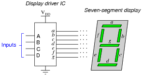
The behavior of the display driver IC may be represented by a truth table with seven outputs: one for each segment of the seven-segment display (a through g). In the following table, a "1" output represents an active display segment, while a "0" output represents an inactive segment:
-
|
|
D
|
C
|
B
|
A
|
a
|
b
|
c
|
d
|
e
|
f
|
g
|
Display
|
|
|
0
|
0
|
0
|
0
|
1
|
1
|
1
|
1
|
1
|
1
|
0
|
"0"
|
|
|
0
|
0
|
0
|
1
|
0
|
1
|
1
|
0
|
0
|
0
|
0
|
"1"
|
|
|
0
|
0
|
1
|
0
|
1
|
1
|
0
|
1
|
1
|
0
|
1
|
"2"
|
|
|
0
|
0
|
1
|
1
|
1
|
1
|
1
|
1
|
0
|
0
|
1
|
"3"
|
|
|
0
|
1
|
0
|
0
|
0
|
1
|
1
|
0
|
0
|
1
|
1
|
"4"
|
|
|
0
|
1
|
0
|
1
|
1
|
0
|
1
|
1
|
0
|
1
|
1
|
"5"
|
|
|
0
|
1
|
1
|
0
|
1
|
0
|
1
|
1
|
1
|
1
|
1
|
"6"
|
|
|
0
|
1
|
1
|
1
|
1
|
1
|
1
|
0
|
0
|
0
|
0
|
"7"
|
|
|
1
|
0
|
0
|
0
|
1
|
1
|
1
|
1
|
1
|
1
|
1
|
"8"
|
|
|
1
|
0
|
0
|
1
|
1
|
1
|
1
|
1
|
0
|
1
|
1
|
"9"
|
|
|
Write the unsimplified SOP or POS expressions (choose the most appropriate form) for outputs a, b, c, and e.
Reveal Answer
Raw (unsimplified) expressions:
|
a = (D + C + B +
|
A
|
)(D +
|
C
|
+ B + A)
|
|
|
b = (D +
|
C
|
+ B +
|
A
|
)(D +
|
C
|
+
|
B
|
+ A)
|
|
|
e =
|
D
|
|
C
|
|
B
|
|
A
|
+
|
D
|
|
C
|
B
|
A
|
+
|
D
|
C B
|
A
|
+ D
|
C
|
|
B
|
|
A
|
|
|
Challenge question: use the laws of Boolean algebra to simplify each of the above expressions into their simplest forms.
Notes:
This shows a very practical example of SOP and POS Boolean forms, and why simplification is necessary to reduce the number of required gates to a practical minimum.
Hide Answer
Question 22:
|
Don't just sit there! Build something!! |
Learning to analyze relay circuits requires much study and practice. Typically, students practice by working through lots of sample problems and checking their answers against those provided by the textbook or the instructor. While this is good, there is a much better way.
You will learn much more by actually
building and analyzing real circuits, letting your test equipment provide the änswers" instead of a book or another person. For successful circuit-building exercises, follow these steps:
-
1.
-
Draw the schematic diagram for the relay circuit to be analyzed.
-
2.
- Carefully build this circuit on a breadboard or other convenient medium.
-
3.
- Check the accuracy of the circuit's construction, following each wire to each connection point, and verifying these elements one-by-one on the diagram.
-
4.
- Analyze the circuit, determining all logic states for given input conditions.
-
5.
- Carefully measure those logic states, to verify the accuracy of your analysis.
-
6.
- If there are any errors, carefully check your circuit's construction against the diagram, then carefully re-analyze the circuit and re-measure.
Always be sure that the power supply voltage levels are within specification for the relay coils you plan to use. I recommend using PC-board relays with coil voltages suitable for single-battery power (6 volt is good). Relay coils draw quite a bit more current than, say, semiconductor logic gates, so use a "lantern" size 6 volt battery for adequate operating life.
One way you can save time and reduce the possibility of error is to begin with a very simple circuit and incrementally add components to increase its complexity after each analysis, rather than building a whole new circuit for each practice problem. Another time-saving technique is to re-use the same components in a variety of different circuit configurations. This way, you won't have to measure any component's value more than once.
Reveal Answer
Let the electrons themselves give you the answers to your own "practice problems"!
Notes:
It has been my experience that students require much practice with circuit analysis to become proficient. To this end, instructors usually provide their students with lots of practice problems to work through, and provide answers for students to check their work against. While this approach makes students proficient in circuit theory, it fails to fully educate them.
Students don't just need mathematical practice. They also need real, hands-on practice building circuits and using test equipment. So, I suggest the following alternative approach: students should build their own "practice problems" with real components, and try to predict the various logic states. This way, the relay theory "comes alive," and students gain practical proficiency they wouldn't gain merely by solving Boolean equations or simplifying Karnaugh maps.
Another reason for following this method of practice is to teach students scientific method: the process of testing a hypothesis (in this case, logic state predictions) by performing a real experiment. Students will also develop real troubleshooting skills as they occasionally make circuit construction errors.
Spend a few moments of time with your class to review some of the "rules" for building circuits before they begin. Discuss these issues with your students in the same Socratic manner you would normally discuss the worksheet questions, rather than simply telling them what they should and should not do. I never cease to be amazed at how poorly students grasp instructions when presented in a typical lecture (instructor monologue) format!
A note to those instructors who may complain about the "wasted" time required to have students build real circuits instead of just mathematically analyzing theoretical circuits:
What is the purpose of students taking your course?
If your students will be working with real circuits, then they should learn on real circuits whenever possible. If your goal is to educate theoretical physicists, then stick with abstract analysis, by all means! But most of us plan for our students to do something in the real world with the education we give them. The "wasted" time spent building real circuits will pay huge dividends when it comes time for them to apply their knowledge to practical problems.
Furthermore, having students build their own practice problems teaches them how to perform primary research, thus empowering them to continue their electrical/electronics education autonomously.
In most sciences, realistic experiments are much more difficult and expensive to set up than electrical circuits. Nuclear physics, biology, geology, and chemistry professors would just love to be able to have their students apply advanced mathematics to real experiments posing no safety hazard and costing less than a textbook. They can't, but you can. Exploit the convenience inherent to your science, and get those students of yours practicing their math on lots of real circuits!
Hide Answer