Superposition theorem
Question 1:
| Don't just sit there! Build something!! |
Learning to mathematically analyze circuits requires much study and practice. Typically, students practice by working through lots of sample problems and checking their answers against those provided by the textbook or the instructor. While this is good, there is a much better way.
You will learn much more by actually building and analyzing real circuits, letting your test equipment provide the änswers" instead of a book or another person. For successful circuit-building exercises, follow these steps:
- 1.
- Carefully measure and record all component values prior to circuit construction.
- 2.
- Draw the schematic diagram for the circuit to be analyzed.
- 3.
- Carefully build this circuit on a breadboard or other convenient medium.
- 4.
- Check the accuracy of the circuit's construction, following each wire to each connection point, and verifying these elements one-by-one on the diagram.
- 5.
- Mathematically analyze the circuit, solving for all values of voltage, current, etc.
- 6.
- Carefully measure those quantities, to verify the accuracy of your analysis.
- 7.
- If there are any substantial errors (greater than a few percent), carefully check your circuit's construction against the diagram, then carefully re-calculate the values and re-measure.
Avoid very high and very low resistor values, to avoid measurement errors caused by meter "loading". I recommend resistors between 1 kW and 100 kW, unless, of course, the purpose of the circuit is to illustrate the effects of meter loading!
One way you can save time and reduce the possibility of error is to begin with a very simple circuit and incrementally add components to increase its complexity after each analysis, rather than building a whole new circuit for each practice problem. Another time-saving technique is to re-use the same components in a variety of different circuit configurations. This way, you won't have to measure any component's value more than once.
Notes:
It has been my experience that students require much practice with circuit analysis to become proficient. To this end, instructors usually provide their students with lots of practice problems to work through, and provide answers for students to check their work against. While this approach makes students proficient in circuit theory, it fails to fully educate them.
Students don't just need mathematical practice. They also need real, hands-on practice building circuits and using test equipment. So, I suggest the following alternative approach: students should build their own "practice problems" with real components, and try to mathematically predict the various voltage and current values. This way, the mathematical theory "comes alive," and students gain practical proficiency they wouldn't gain merely by solving equations.
Another reason for following this method of practice is to teach students scientific method: the process of testing a hypothesis (in this case, mathematical predictions) by performing a real experiment. Students will also develop real troubleshooting skills as they occasionally make circuit construction errors.
Spend a few moments of time with your class to review some of the "rules" for building circuits before they begin. Discuss these issues with your students in the same Socratic manner you would normally discuss the worksheet questions, rather than simply telling them what they should and should not do. I never cease to be amazed at how poorly students grasp instructions when presented in a typical lecture (instructor monologue) format!
A note to those instructors who may complain about the "wasted" time required to have students build real circuits instead of just mathematically analyzing theoretical circuits:
What is the purpose of students taking your course?
If your students will be working with real circuits, then they should learn on real circuits whenever possible. If your goal is to educate theoretical physicists, then stick with abstract analysis, by all means! But most of us plan for our students to do something in the real world with the education we give them. The "wasted" time spent building real circuits will pay huge dividends when it comes time for them to apply their knowledge to practical problems.
Furthermore, having students build their own practice problems teaches them how to perform primary research, thus empowering them to continue their electrical/electronics education autonomously.
In most sciences, realistic experiments are much more difficult and expensive to set up than electrical circuits. Nuclear physics, biology, geology, and chemistry professors would just love to be able to have their students apply advanced mathematics to real experiments posing no safety hazard and costing less than a textbook. They can't, but you can. Exploit the convenience inherent to your science, and get those students of yours practicing their math on lots of real circuits!
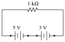
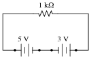
Question 2:
Suppose we have a single resistor powered by two series-connected voltage sources. Each of the voltage sources is ïdeal," possessing no internal resistance:
|
|
Calculate the resistor's voltage drop and current in this circuit.
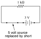
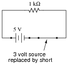
Now, suppose we were to remove one voltage source from the circuit, replacing it with its internal resistance (0 W). Re-calculate the resistor's voltage drop and current in the resulting circuit:
|
|
Now, suppose we were to remove the other voltage source from the circuit, replacing it with its internal resistance (0 W). Re-calculate the resistor's voltage drop and current in the resulting circuit:
|
|
One last exercise: ßuperimpose" (add) the resistor voltages and superimpose (add) the resistor currents in the last two circuit examples, and compare these voltage and current figures with the calculated values of the original circuit. What do you notice?
With 3 volt voltage source only: ER = 3 volts ; IR = 3 mA
With 5 volt voltage source only: ER = 5 volts ; IR = 5 mA
5 volts + 3 volts = 8 volts
5 mA + 3 mA = 8 mA
Notes:
This circuit is so simple, students should not even require the use of a calculator to determine the current figures. The point of it is, to get students to see the concept of superposition of voltages and currents.
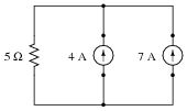
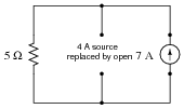
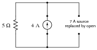
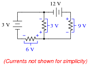
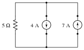
Question 3:
Suppose we have a single resistor powered by two parallel-connected current sources. Each of the current sources is ïdeal," possessing infinite internal resistance:
|
|
Calculate the resistor's voltage drop and current in this circuit.
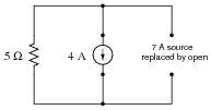
Now, suppose we were to remove one current source from the circuit, replacing it with its internal resistance (� W). Re-calculate the resistor's voltage drop and current in the resulting circuit:
|
|
Now, suppose we were to remove the other current source from the circuit, replacing it with its internal resistance (� W). Re-calculate the resistor's voltage drop and current in the resulting circuit:
|
|
One last exercise: ßuperimpose" (add) the resistor voltages and superimpose (add) the resistor currents in the last two circuit examples, and compare these voltage and current figures with the calculated values of the original circuit. What do you notice?
With 7 amp current source only: ER = 35 volts ; IR = 7 A
With 4 amp current source only: ER = 20 volts ; IR = 4 A
35 volts + 20 volts = 55 volts
7 A + 4 A = 11 A
Notes:
This circuit is so simple, students should not even require the use of a calculator to determine the current figures. If students are not familiar with current sources, this question provides an excellent opportunity to review them. The main point of the question is, however, to get students to see the concept of superposition of voltages and currents.
Question 4:
The Superposition Theorem is a very important concept used to analyze both DC and AC circuits. Define this theorem in your own words, and also state the necessary conditions for it to be freely applied to a circuit.
Notes:
As the answer states, students have a multitude of resources to consult on this topic. It should not be difficult for them to ascertain what this important theorem is and how it is applied to the analysis of circuits.
Be sure students understand what the terms linear and bilateral mean with reference to circuit components and the necessary conditions for Superposition Theorem to be applied to a circuit. Point out that it is still possible to apply the Superposition Theorem to a circuit containing nonlinear or unilateral components if we do so carefully (i.e. under narrowly defined conditions).
Question 5:
Explain in your own words how to apply the Superposition Theorem to calculate the amount of current through the load resistor in this circuit:
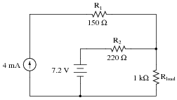
|
|
Iload = 6.623 mA
Notes:
Here is a circuit students will not be able to analyze by series-parallel analysis, since it is impossible to reduce all the resistors in it to a single equivalent resistance. It is cases like this that really showcase the power of Superposition as an analysis technique.
Question 6:
The Superposition Theorem works nicely to calculate voltages and currents in resistor circuits. But can it be used to calculate power dissipations as well? Why or why not? Be specific with your answer.
Notes:
In order to answer this question correctly (without just looking up the answer in a book), students will have to perform a few power calculations in simple, multiple-source circuits. It may be worthwhile to work through a couple of example problems during discussion time, to illustrate the answer.
Despite the fact that resistor power dissipations cannot be superimposed to obtain the answer(s), it is still possible to use the Superposition Theorem to calculate resistor power dissipations in a multiple-source circuit. Challenge your students with the task of applying this theorem for solving power dissipations in a circuit.
Question 7:
Note that this circuit is impossible to reduce by regular series-parallel analysis:
|
|
However, the Superposition Theorem makes it almost trivial to calculate all the voltage drops and currents:
|
|
Explain the procedure for applying the Superposition Theorem to this circuit.
Notes:
I really enjoy covering the Superposition Theorem in class with my students. It's one of those rare analysis techniques that is intuitively obvious and yet powerful at the same time. Because the principle is so easy to learn, I highly recommend you leave this question for your students to research, and let them fully present the answer in class rather than you explain any of it.
Question 8:
Use the Superposition Theorem to calculate the amount of current going through the 55 W heater element. Ignore all wire and connection resistances, only considering the resistance of each fuse in addition to the heater element resistance:
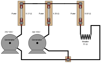
|
|
Follow-up question: explain how you could use the Superposition Theorem to calculate current going through the short length of wire connecting the two generators together:
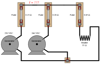
|
|
Notes:
Though there are other methods of analysis for this circuit, it is still a good application of Superposition Theorem.
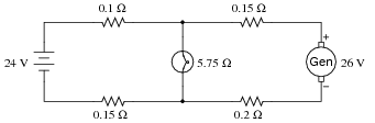
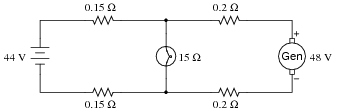
Question 9:
Suppose a DC generator is powering an electric motor, which we model as a 100 W resistor:
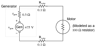
|
|
Calculate the amount of current this generator will supply to the motor and the voltage measured across the motor's terminals, taking into account all the resistances shown (generator internal resistance rgen, wiring resistances Rwire, and the motor's equivalent resistance).
Now suppose we connect an identical generator in parallel with the first, using connecting wire so short that we may safely discount its additional resistance:
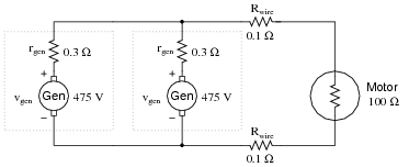
|
|
Use the Superposition Theorem to re-calculate the motor current and motor terminal voltage, commenting on how these figures compare with the first calculation (using only one generator).
Imotor = 4.726 amps Vmotor = 472.6 volts
With two generators connected:
Imotor = 4.733 amps Vmotor = 473.3 volts
Challenge question: how much current does each generator supply to the circuit when there are two generators connected in parallel?
Notes:
Some students will erroneously leap to the conclusion that another generator will send twice the current through the load (with twice the voltage drop across the motor terminals!). Such a conclusion is easy to reach if one does not fully understand the Superposition Theorem.
Question 10:
Calculate the charging current through each battery, using the Superposition Theorem (ignore all wire and connection resistances - only consider the resistance of each fuse):
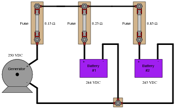
|
|
Ibattery1 = 13.91 A
Ibattery2 = 2.91 A
Follow-up question: identify any safety hazards that could arise as a result of excessive resistance in the fuse holders (e.g., corrosion build-up on the metal tabs where the fuse clips in to the fuse-holder).
Notes:
Though there are other methods of analysis for this circuit, it is still a good application of Superposition Theorem.
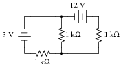
Question 11:
Suppose we have a single resistor powered by two series-connected voltage sources. Each of the voltage sources is ïdeal," possessing no internal resistance:
|
|
Calculate the resistor's voltage drop and current in this circuit.
Now, suppose we were to remove one voltage source from the circuit, replacing it with its internal resistance (0 W). Re-calculate the resistor's voltage drop and current in the resulting circuit:
|
|
Now, suppose we were to remove the other voltage source from the circuit, replacing it with its internal resistance (0 W). Re-calculate the resistor's voltage drop and current in the resulting circuit:

|
|
One last exercise: ßuperimpose" (add) the resistor voltages and superimpose (add) the resistor currents in the last two circuit examples, and compare these voltage and current figures with the calculated values of the original circuit. What do you notice?
With 3 volt voltage source only: ER = 3 volts ; IR = 3 mA
With 5 volt voltage source only: ER = 5 volts ; IR = 5 mA
5 volts - 3 volts = 2 volts
5 mA - 3 mA = 2 mA
Notes:
This circuit is so simple, students should not even require the use of a calculator to determine the current figures. The point of it is, to get students to see the concept of superposition of voltages and currents.
Ask your students if they think it is important to keep track of voltage polarities and current directions in the superposition process. Why or why not?
Question 12:
Suppose we have a single resistor powered by two parallel-connected current sources. Each of the current sources is ïdeal," possessing infinite internal resistance:
|
|
Calculate the resistor's voltage drop and current in this circuit.
Now, suppose we were to remove one current source from the circuit, replacing it with its internal resistance (� W). Re-calculate the resistor's voltage drop and current in the resulting circuit:

|
|
Now, suppose we were to remove the other current source from the circuit, replacing it with its internal resistance (� W). Re-calculate the resistor's voltage drop and current in the resulting circuit:
|
|
One last exercise: ßuperimpose" (add) the resistor voltages and superimpose (add) the resistor currents in the last two circuit examples, and compare these voltage and current figures with the calculated values of the original circuit. What do you notice?
With 7 amp current source only: ER = 35 volts ; IR = 7 A
With 4 amp current source only: ER = 20 volts ; IR = 4 A
35 volts - 20 volts = 15 volts
7 A - 4 A = 3 A
Notes:
This circuit is so simple, students should not even require the use of a calculator to determine the current figures. If students are not familiar with current sources, this question provides an excellent opportunity to review them. The main point of the question is, however, to get students to see the concept of superposition of voltages and currents.
Question 13:
A windmill-powered generator and a battery work together to supply DC power to a light bulb. Calculate the amount of current through each of these three components, given the values shown in the schematic diagram. Assume internal resistances of the generator and battery to be negligible:
|
|
Ibatt = Ibulb = Igen =
Notes:
Discuss your students' procedures with them in class, so that all may see how a problem such as this may be solved. Superposition theorem is probably the most direct way of solving for all currents, although students could apply Kirchhoff's Laws if they are familiar with solving linear systems of equations.
Question 14:
A windmill-powered generator and a battery work together to supply DC power to a light bulb. Calculate the amount of current through each of these three components, given the values shown in the schematic diagram. Assume internal resistances of the generator and battery to be negligible:
|
|
Ibatt = Ibulb = Igen =
Notes:
Discuss your students' procedures with them in class, so that all may see how a problem such as this may be solved. Superposition theorem is probably the most direct way of solving for all currents, although students could apply Kirchhoff's Laws if they are familiar with solving linear systems of equations.
Question 15:
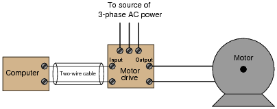
Electrical signals are frequently used in industrial control applications to communicate information from one device to another. An example of this is motor speed control, where a computer outputs a speed command signal to a motor "drive" circuit, which then provides metered power to an electric motor:
|
|
Two common standards for analog control signals are 1-5 volts DC and 4-20 mA DC. In either case, the motor will spin faster when this signal from the computer grows in magnitude (1 volt = motor stopped, 5 volts = motor runs at full speed; or 4 mA = motor stopped, 20 mA = motor runs at full speed).
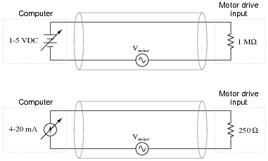
At first, it would seem as though the choice between 1-5 volts and 4-20 mA as control signal standards is arbitrary. However, one of these standards exhibits much greater immunity to induced noise along the two-wire cable than the other. Shown here are two equivalent schematics for these signal standards, complete with an AC voltage source in series to represent the "noise" voltage picked up along the cable's length:
|
|
Use the superposition theorem to qualitatively determine which signal standard drops the greatest amount of noise voltage across the motor drive input's resistance, thereby most affecting the motor speed control.
Follow-up question: what bad effects do you think noise superimposed on the DC signal cable would have on motor speed control?
Challenge question: why do you suppose the 1-5 volt signal system requires a much greater input impedance (1 MW) than the 4-20 mA signal system? What might happen to the voltage signal received at the motor drive's input terminals if the input resistance were much less?
Notes:
This is s very practical question, as induced noise is no academic matter in real industrial control systems. This is especially true around motor drive circuits, which are well known for their ability to generate lots of electrical noise!
Some students may suggest that the distinction between voltage and current signals is moot because shielded-pair cable is suppose to all but eliminate induced noise. In answer to this (good) question, it should be noted that real-life conditions are never ideal, and that induced noise (to some degree) is an unavoidable fact of life, especially in many industrial environments.
The challenge question may seem unanswerable until one considers the unavoidable resistance along the length of the signal cable and calculates the effects of voltage drop along the wire length for a huge input resistance versus a small input resistance.
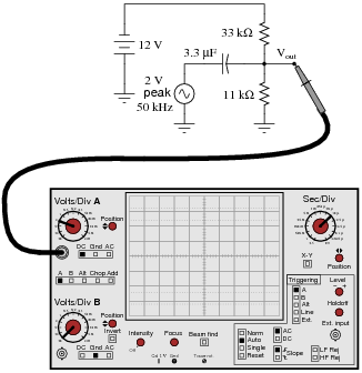
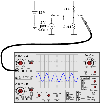
Question 16:
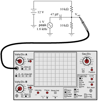
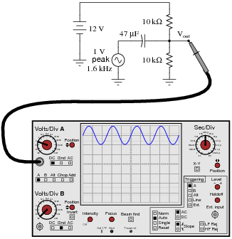
Sketch the approximate waveform of this circuit's output signal (Vout) on the screen of the oscilloscope:
|
|
Hint: use the Superposition Theorem!
|
|
Follow-up question: what would the oscilloscope display look like if the coupling switch for channel A had been set to ÄC" instead of "DC"?
Notes:
Note that the capacitor size has been chosen for negligible capacitive reactance (XC) at the specific frequency, such that the 10 kW DC bias resistors present negligible loading to the coupled AC signal. This is typical for this type of biasing circuit.
Aside from giving students an excuse to apply the Superposition Theorem, this question previews a circuit topology that is extremely common in transistor amplifiers.
Question 17:
Sketch the approximate waveform of this circuit's output signal (Vout) on the screen of the oscilloscope:
|
|
Hint: use the Superposition Theorem!
|
|
Follow-up question: explain why it is acceptable to use a polarized (polarity-sensitive) capacitor in this circuit when it is clearly connected to a source of AC. Why is it not damaged by the AC voltage when used like this?
Notes:
Note that the capacitor size has been chosen for negligible capacitive reactance (XC) at the specific frequency, such that the 10 kW DC bias resistors present negligible loading to the coupled AC signal. This is typical for this type of biasing circuit.
Aside from giving students an excuse to apply the Superposition Theorem, this question previews a circuit topology that is extremely common in transistor amplifiers.