Th\'evenin's, Norton's, and Maximum Power Transfer theorems
Question 1:
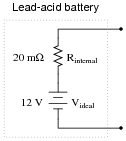
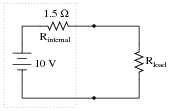
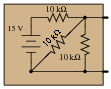
Suppose a 12 volt lead-acid battery has an internal resistance of 20 milli-ohms (20 mW):
|
|
If a short-circuit were placed across the terminals of this large battery, the fault current would be quite large: 600 amps!
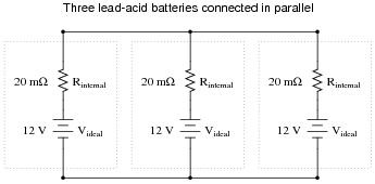
Now suppose three of these batteries were connected directly in parallel with one another:
|
|
Reduce this network of parallel-connected batteries into either a Thévenin or a Norton equivalent circuit, and then re-calculate the fault current available at the terminals of the three-battery "bank" in the event of a direct short-circuit.
Follow-up question: explain what practical importance this question has for parallel-connected batteries, and how either Thévenin's or Norton's theorems makes the concept easier to explain to someone else. What safety issues might be raised by the parallel connection of large batteries such as these?
Notes:
Ask your students whether they used Thévenin's Theorem or Norton's theorem to solve for the fault current. Have students demonstrate the analysis both ways to see which is easiest to understand.
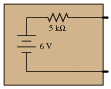
Question 2:
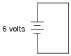
What would happen if a wire having no resistance at all (0 W) were connected directly across the terminals of a 6-volt battery? How much current would result, according to Ohm's Law?
|
|
Suppose we were to short-circuit a 6-volt battery in the manner just described and measure 8 amps of current. Why don't the calculated figures from the previous paragraph agree with the actual measurement?
If you think that the wire used in the experiment is not resistance-less (i.e. it does have resistance), and that this accounts for the disparity between the predicted and measured amounts of current, you are partially correct. Realistically, a small piece of wire such as that used in the experiment will have a few tenths of an ohm of resistance. However, if you re-calculate current with a wire resistance of 0.1 W, you will still find a large disparity between your prediction and the actual measured current in this short-circuit.
Follow-up question #1: explain why wire resistance alone does not explain the modest short-circuit current.
Follow-up question #2: identify at least one safety hazard associated with a real experiment such as this.
Notes:
Remind students that short-circuit testing of electrical power sources can be dangerous. A student of mine once stuffed a 6-volt "lantern" battery in his tool pouch, only to have it discharge smoke an hour later, after the battery terminals had been shorted together by a wrench handle!
No, Ohm's Law is not being cheated here: shorting a voltage source with a 0 W conductor will not result in infinite current, because there are other sources of resistance in such a circuit. The task here is to determine where those sources might be, and how they could be located.
Question 3:
| Don't just sit there! Build something!! |
Learning to mathematically analyze circuits requires much study and practice. Typically, students practice by working through lots of sample problems and checking their answers against those provided by the textbook or the instructor. While this is good, there is a much better way.
You will learn much more by actually building and analyzing real circuits, letting your test equipment provide the änswers" instead of a book or another person. For successful circuit-building exercises, follow these steps:
- 1.
- Carefully measure and record all component values prior to circuit construction.
- 2.
- Draw the schematic diagram for the circuit to be analyzed.
- 3.
- Carefully build this circuit on a breadboard or other convenient medium.
- 4.
- Check the accuracy of the circuit's construction, following each wire to each connection point, and verifying these elements one-by-one on the diagram.
- 5.
- Mathematically analyze the circuit, solving for all values of voltage, current, etc.
- 6.
- Carefully measure those quantities, to verify the accuracy of your analysis.
- 7.
- If there are any substantial errors (greater than a few percent), carefully check your circuit's construction against the diagram, then carefully re-calculate the values and re-measure.
Avoid very high and very low resistor values, to avoid measurement errors caused by meter "loading". I recommend resistors between 1 kW and 100 kW, unless, of course, the purpose of the circuit is to illustrate the effects of meter loading!
One way you can save time and reduce the possibility of error is to begin with a very simple circuit and incrementally add components to increase its complexity after each analysis, rather than building a whole new circuit for each practice problem. Another time-saving technique is to re-use the same components in a variety of different circuit configurations. This way, you won't have to measure any component's value more than once.
Notes:
It has been my experience that students require much practice with circuit analysis to become proficient. To this end, instructors usually provide their students with lots of practice problems to work through, and provide answers for students to check their work against. While this approach makes students proficient in circuit theory, it fails to fully educate them.
Students don't just need mathematical practice. They also need real, hands-on practice building circuits and using test equipment. So, I suggest the following alternative approach: students should build their own "practice problems" with real components, and try to mathematically predict the various voltage and current values. This way, the mathematical theory "comes alive," and students gain practical proficiency they wouldn't gain merely by solving equations.
Another reason for following this method of practice is to teach students scientific method: the process of testing a hypothesis (in this case, mathematical predictions) by performing a real experiment. Students will also develop real troubleshooting skills as they occasionally make circuit construction errors.
Spend a few moments of time with your class to review some of the "rules" for building circuits before they begin. Discuss these issues with your students in the same Socratic manner you would normally discuss the worksheet questions, rather than simply telling them what they should and should not do. I never cease to be amazed at how poorly students grasp instructions when presented in a typical lecture (instructor monologue) format!
A note to those instructors who may complain about the "wasted" time required to have students build real circuits instead of just mathematically analyzing theoretical circuits:
What is the purpose of students taking your course?
If your students will be working with real circuits, then they should learn on real circuits whenever possible. If your goal is to educate theoretical physicists, then stick with abstract analysis, by all means! But most of us plan for our students to do something in the real world with the education we give them. The "wasted" time spent building real circuits will pay huge dividends when it comes time for them to apply their knowledge to practical problems.
Furthermore, having students build their own practice problems teaches them how to perform primary research, thus empowering them to continue their electrical/electronics education autonomously.
In most sciences, realistic experiments are much more difficult and expensive to set up than electrical circuits. Nuclear physics, biology, geology, and chemistry professors would just love to be able to have their students apply advanced mathematics to real experiments posing no safety hazard and costing less than a textbook. They can't, but you can. Exploit the convenience inherent to your science, and get those students of yours practicing their math on lots of real circuits!
Question 4:
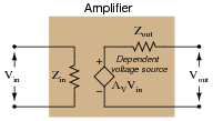
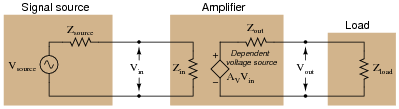
Sometimes you will see amplifier circuits expressed as collections of impedances and dependent sources:
|
|
With this model, the amplifier appears as a load (Zin) to whatever signal source its input is connected to, boosts that input voltage by the gain factor (AV), then outputs the boosted signal through a series output impedance (Zout) to whatever load is connected to the output terminals:
|
|
Explain why all these impedances (shown as resistors) are significant to us as we seek to apply amplifier circuits to practical applications. Which of these impedances do you suppose are typically easier for us to change, if they require changing at all?
Notes:
This question has multiple purposes: to introduce students to the modeling concept of a dependent source, to show how an amplifier circuit may be modeled using such a dependent source, and to probe into the importance of impedances in a complete amplification system: source, amplifier, and load. Many interesting things to discuss here!
Question 5:
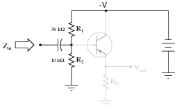
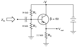
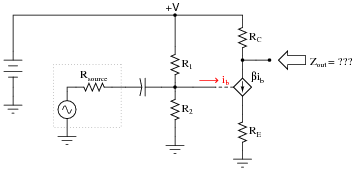
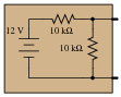
The voltage divider network employed to create a DC bias voltage for many transistor amplifier circuits has its own effect on amplifier input impedance. Without considering the presence of the transistor or the emitter resistance, calculate the impedance as ßeen" from the input terminal resulting from the two resistors R1 and R2 in the following common-collector amplifier circuit:
|
|
Remember, what you are doing here is actually determining the Thévenin/Norton equivalent resistance as seen from the input terminal by an AC signal. The input coupling capacitor reactance is generally small enough to be safely ignored.
Next, calculate the input impedance of the same circuit, this time considering the presence of the transistor and emitter resistor, assuming a current gain (b or hfe) of 60, and the following formula for impedance at the base resulting from b and RE:
|
|
|
Develop an equation from the steps you take in calculating this impedance value.
Zin (complete circuit) � 7.514 kW
|
Notes:
This question is primarily an exercise in applying Thévenin's theorem to the amplifier circuit. The most confusing point of this for most students seems to be how to regard the DC power supply. A review of Thévenin equivalent circuit procedures and calculations might be in order here.
To be proper, the transistor's dynamic emitter resistance (r�e) could also be included in this calculation, but this just makes things more complex. For this question, I wanted to keep things as simple as possible by just having students concentrate on the issue of integrating the voltage divider impedance with the transistor's base impedance. With an emitter resistor value of 1500 ohms, the dynamic emitter resistance is negligibly small anyway.
Question 6:
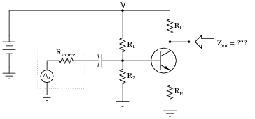
Determining the output impedance of a common-emitter amplifier is impossible unless we know how to model the transistor in terms of components whose behavior is simple to express.
|
|
When in its active mode, a transistor operates like a current regulator. This is similar enough to the behavior of a current source that we may use a source to model the transistor's behavior for the sake of this impedance determination:
|
|
Now, apply the same steps you would use in determining the Thévenin or Norton equivalent impedance to the output of this amplifier circuit, and this will yield the amplifier's output impedance. Draw an equivalent circuit for the amplifier during this Thévenizing/Nortonizing process to show how the output impedance is determined.
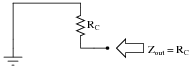
|
|
I'm leaving it up to you to explain why the amplifier circuit reduces to something as simple as this!
Follow-up question: what is the significance of showing the transistor as a current source using a diamond-shaped symbol rather than a circle? You should be familiar by now with circular current source symbols, but what does a diamond-shaped current source symbol specifically represent in a schematic diagram?
Notes:
The main problem students usually have when Thévenizing or Nortonizing this circuit is what to do with the current source. They may remember that voltage sources become shorted during the impedance-determination process, but usually make the mistake of doing the exact same thing with current sources. Remind your students if necessary that each source is to be replaced by its respective internal impedance. For voltage sources (with zero internal impedance, ideally) it means replacing them with short circuits. For current sources (with infinite internal impedance, ideally) it means replacing them with open circuits.
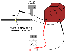
Question 7:
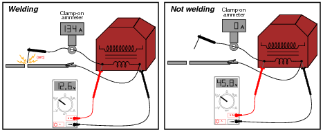
An electric arc welder is a low-voltage, high-current power source designed to supply enough electric current to sustain an arc capable of welding metal with its high temperature:
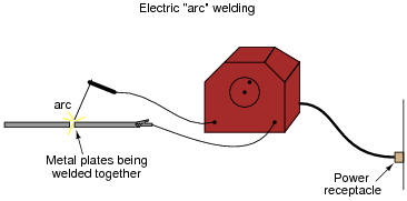
|
|
It is possible to derive a Norton equivalent circuit for an arc welder based on empirical measurements of voltage and current. Take for example these measurements, under loaded and no-load conditions:
|
|
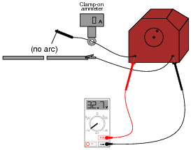
|
|
Based on these measurements, draw a Norton equivalent circuit for the arc welder.
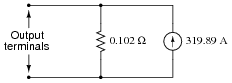
|
|
Notes:
This practical scenario shows how Norton's theorem may be used to "model" a complex device as two simple components (current source and resistor). Of course, we must make certain assumptions when modeling in this fashion: we assume, for instance, that the arc welder is a linear device, which may or may not be true.
Incidentally, there is such a thing as a DC-measuring clamp-on ammeter as shown in the illustrations, in case any one of your students ask. AC clamp-on meters are simpler, cheaper, and thus more popularly known, but devices using the Hall effect are capable of inferring DC current by the strength of an unchanging magnetic field, and these Hall-effect devices are available at modest expense.
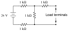
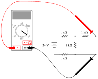
Question 8:
Thévenize this resistive network:
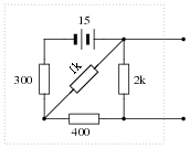
|
|
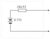
|
|
Notes:
Nothing but practice here. Have your students demonstrate how they did the Thévenin conversion, step-by-step.
Question 9:
Resistive voltage dividers are very useful and popular circuits. However, it should be realized that their output voltages ßag" under load:
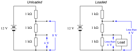
|
|
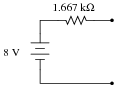
Just how much a voltage divider's output will sag under a given load may be a very important question in some applications. Take for instance the following application where we are using a resistive voltage divider to supply an engine sensor with reduced voltage (8 volts) from the 12 volt battery potential in the automobile:
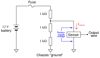
|
|
If the sensor draws no current (Isensor = 0 mA), then the voltage across the sensor supply terminals will be 8 volts. However, if we were asked to predict the voltage across the sensor supply terminals for a variety of different sensor current conditions, we would be faced with a much more complex problem:
-
Sensor current (Isensor) Sensor supply voltage
0 mA 8 volts
1 mA
2 mA
3 mA
4 mA
5 mA
One technique we could use to simplify this problem is to reduce the voltage divider resistor network into a Thévenin equivalent circuit. With the three-resistor divider reduced to a single resistor in series with an equivalent voltage source, the calculations for sensor supply voltage become much simpler.
Show how this could be done, then complete the table of sensor supply voltages shown above.
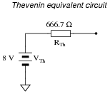
|
|
-
Sensor current (Isensor) Sensor supply voltage
0 mA 8 volts
1 mA 7.333 volts
2 mA 6.667 volts
3 mA 6 volts
4 mA 5.333 volts
5 mA 4.667 volts
Follow-up question: if we cannot allow the sensor supply voltage to fall below 6.5 volts, what is the maximum amount of current it may draw from this voltage divider circuit?
Challenge question: figure out how to solve for these same voltage figures without reducing the voltage divider circuit to a Thévenin equivalent.
Notes:
Students are known to ask, "When are we ever going to use Thévenin's Theorem?" as this concept is introduced in their electronics coursework. This is a valid question, and should be answered with immediate, practical examples. This question does exactly that: demonstrate how to predict voltage ßag" for a loaded voltage divider in such a way that is much easier than using Ohm's Law and Kirchhoff's Laws directly.
Note the usage of European schematic symbols in this question. Nothing significant about this choice - just an opportunity for students to see other ways of drawing schematics.
Note also how this question makes use of ground symbols, but in a way where the concept is introduced gently: the first (example) schematics do not use ground symbols, whereas the practical (automotive) circuit does.
Question 10:
Give a step-by-step procedure for "Thévenizing" any circuit: finding the Thévenin equivalent voltage (VThevenin) and Thévenin equivalent resistance (RThevenin).
- �
- Step #1:
- �
- Step #2:
Follow-up question: describe the difference in how one must consider voltage sources versus current sources when calculating the equivalent circuit's resistance (RThevenin) of a complex circuit containing both types of sources?
Notes:
I really mean what I say here about looking this up in a textbook. Thévenin's Theorem is a very well-covered subject in many books, and so it is perfectly reasonable to expect students will do this research on their own and come back to class with a complete answer.
The follow-up question is very important, because some circuits (especially transistor amplifier circuits) contain both types of sources. Knowing how to consider each one in the process of calculating the Thévenin equivalent resistance for a circuit is very important. When performing this analysis on transistor amplifiers, the circuit often becomes much simpler than its original form with all the voltage sources shorted and current sources opened!
Question 11:
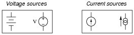
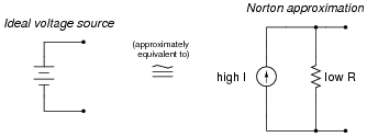
A voltage source is a source of electricity that (ideally) outputs a constant voltage. That is, a perfect voltage source will hold its output voltage constant regardless of the load imposed upon it:
|
|
In real life, there is no such thing as a perfect voltage source, but sources having extremely low internal resistance come close.
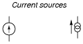
Another type of electricity source is the current source, which (ideally) outputs a constant current regardless of the load imposed upon it. A common symbol for a current source is a circle with an arrow inside (always pointing in the direction of conventional flow, not electron flow!). Another symbol is two intersecting circles, with an arrow nearby pointing in the direction of conventional flow:
|
|
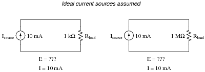
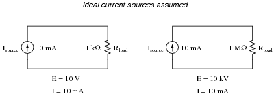
Predict how an ideal current source would behave for the following two load scenarios:
|
|
|
|
Follow-up question: identify the polarity of the voltage drops across the resistors in the circuits shown above.
Notes:
Let students know that there really is such a thing as a perfect current source, just as there is no such thing as a perfect voltage source. However, there are devices the closely approximate ideal current sources (current transformers in AC circuits and "current mirror" DC transistor circuits, for example).
Question 12:
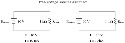
Ideal voltage sources and ideal current sources, while both being sources of electrical power, behave very differently from one another:
|
|
Explain how each type of electrical source would behave if connected to a variable-resistance load. As this variable resistance were increased and decreased, how would each type of source respond?
Notes:
Ask your students to think of a few "thought experiment" scenarios where voltage and current sources could be put to test. Have them invent voltage and current values for these voltage and current sources, respectively, then calculate all other circuit parameters given several different values of load resistance.
Question 13:
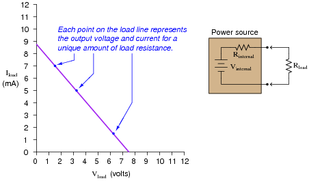
A very common sort of graph used in electronics work is the load line, showing all possibilities of load voltage and load current that a particular power source is able to supply to a load:

|
|
Note how the load line shows the voltage ßag" of the power source in relation to the amount of current drawn by the load. At high currents, the output voltage will be very low (upper-left end of load line). At low currents, the output voltage will be near its maximum (lower-right end of load line). If all internal components of the power source are linear in nature, the load line will always be perfectly straight.
Plot the load line for a power source having an internal voltage (Vinternal) of 11 volts and an internal resistance (Rinternal) of 1.2 kW. Superimpose your load line onto the load line graph shown above. Hint: it only takes two points to define a line!
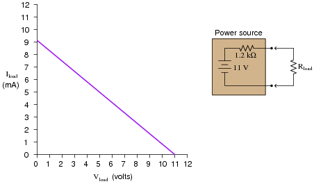
|
|
Hint: the easiest points on find on this load line are the points representing open-circuit and short-circuit conditions (i.e. Rload = � W and Rload = 0 W, respectively).
Follow-up questions: what will happen to the load line if we change the internal resistance of the power source circuit? What will happen to the load line if we change the internal voltage value of the power source circuit?
Notes:
The purpose of this question is to lend an analytical geometric perspective to the subject of power source behavior, by showing how the output voltage and current may be plotted on a graph. The condition of circuit linearity is important, as it permits us to confidently plot the load line by finding only two points on it.
Question 14:
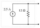
Give a step-by-step procedure for reducing this circuit to a Norton equivalent circuit (one current source in parallel with one resistor):

|
|
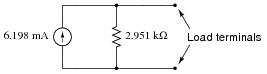
|
|
Notes:
It should be easy for your students to research an algorithm (step-by-step procedure) for determining a Norton equivalent circuit. Let them do the work, and explain it to you and their classmates!
Question 15:
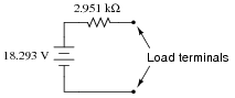
Suppose you had an AC/DC power supply, which performed as follows (open-circuit and loaded test conditions):
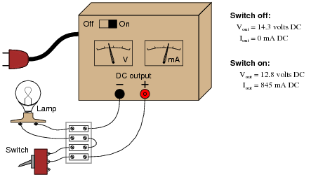
|
|
Draw a Thévenin equivalent circuit to model the behavior of this power supply.
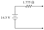
|
|
Follow-up question: is the switch shown in the on or off position, in the pictorial diagram?
Notes:
Discuss with your students how Thévenin's theorem allows us to model fairly complex power-supply circuits as simply a voltage source and series resistance (at least approximately). Discuss also the limitations of this modeling, especially in light of the condition of linearity for the proper application of Thévenin's theorem.
Question 16:
Suppose you were handed a black box with two metal terminals on one side, for attaching electrical (wire) connections. Inside this box, you were told, was a voltage source (an ideal voltage source connected in series with a resistance):

|
|
How would you experimentally determine the voltage of the ideal voltage source inside this box, and how would you experimentally determine the resistance of the series resistor? By ëxperimentally," I mean determine voltage and resistance using actual test equipment rather than assuming certain component values (remember, this "black box" is sealed, so you cannot look inside!).
Notes:
Ask your students how they would apply this technique to an abstract circuit problem, to reduce a complex network of sources and resistances to a single voltage source and single series resistance (Thévenin equivalent).
Question 17:
Suppose you were handed a black box with two metal terminals on one side, for attaching electrical (wire) connections. Inside this box, you were told, was a current source (an ideal current source connected in parallel with a resistance):

|
|
How would you experimentally determine the current of the ideal current source inside this box, and how would you experimentally determine the resistance of the parallel resistor? By ëxperimentally," I mean determine current and resistance using actual test equipment rather than assuming certain component values (remember, this "black box" is sealed, so you cannot look inside!).
Notes:
Ask your students how they would apply this technique to an abstract circuit problem, to reduce a complex network of sources and resistances to a single current source and single parallel resistance (Norton equivalent).
Question 18:
Suppose you were handed a black box with two metal terminals on one side, for attaching electrical (wire) connections. Inside this box, you were told, was a voltage source connected in series with a resistance.
|
|
Your task was to experimentally determine the values of the voltage source and the resistor inside the box, and you did just that. From your experimental data you then sketched a circuit with the following component values:
|
|
However, you later discovered that you had been tricked. Instead of containing a single voltage source and a single resistance, the circuit inside the box actually looked like this:
|
|
Demonstrate that these two different circuits are indistinguishable from the perspective of the two metal terminals, and explain what general principle this equivalence represents.
Notes:
Ask your students to clearly state Thévenin's Theorem, and explain how it may be applied to the two-resistor circuit to obtain the one-resistor circuit.
Question 19:
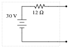
Give a step-by-step procedure for reducing this circuit to a Thévenin equivalent circuit (one voltage source in series with one resistor):
|
|
|
|
Notes:
It should be easy for your students to research an algorithm (step-by-step procedure) for determining a Thévenin equivalent circuit. Let them do the work, and explain it to you and their classmates!
Question 20:
Suppose you were handed a black box with two metal terminals on one side, for attaching electrical (wire) connections. Inside this box, you were told, was a current source connected in parallel with a resistance.

|
|
Your task was to experimentally determine the values of the current source and the resistor inside the box, and you did just that. From your experimental data you then sketched a circuit with the following component values:
|
|
However, you later discovered that you had been tricked. Instead of containing a current source and a resistor, the circuit inside the box was actually a voltage source connected in series with a resistor:
|
|
Demonstrate that these two different circuits are indistinguishable from the perspective of the two metal terminals, and explain what general principle this equivalence represents.
Follow-up question: give a step-by-step procedure for converting a Thévenin equivalent circuit into a Norton equivalent circuit, and visa-versa.
Notes:
Ask your students to clearly state both Thévenin's and Norton's Theorems, and also discuss why both these theorems are important electrical analysis tools.
Question 21:
An AC voltage source with an internal ("Thévenin") resistance of 50 W is connected to a step-down transformer with a winding ratio of 10:1. What is the equivalent source voltage and resistance, as seen from the load terminals?
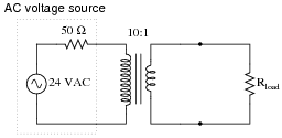
|
|
Notes:
Ask your students to explain how they obtained the equivalent voltage and current figures for this transformer-coupled source. Is there a scenario we could imagine the source being placed in that would allow us to obtain these figures without knowing anything about transformer impedance matching?
Question 22:
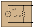
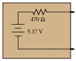
Calculate the voltage dropped across the load resistor, and the current through the load resistor, for the following load resistance values in this circuit:
|
|
-
Rload Eload Iload
1 k W
2 k W
5 k W
8 k W
10 k W
Do the "boxed" components in this circuit behave more like a constant voltage source, or a constant current source? Explain your answer.
Follow-up question: would you say that voltage sources are typically characterized as having high internal resistances or low internal resistances? What about current sources? Explain your answers.
Notes:
Ask your students to make a general prediction about the internal resistance of voltage sources. Based on our calculations in this circuit, would you expect voltage sources to have high internal resistance or low internal resistance? Also ask what constitutes a "high" or a "low" internal resistance for a power source. Is this a relative determination, or an absolute determination?
Question 23:
Calculate the voltage dropped across the load resistor, and the current through the load resistor, for the following load resistance values in this circuit:
|
|
-
Rload Eload Iload
1 k W
2 k W
5 k W
8 k W
10 k W
Do the "boxed" components in this circuit behave more like a constant voltage source, or a constant current source? Explain your answer.
Follow-up question #1: would you say that voltage sources are typically characterized as having high internal resistances or low internal resistances? What about current sources? Explain your answers.
Follow-up question #2: although it is difficult to find real devices that approximate ideal current sources, there are a few that do. An AC device called a "current transformer" is one of them. Describe which scenario would be the safest from a perspective of shock hazard: an open-circuited current transformer, or a shirt-circuited current transformer. Why is this?
Notes:
Ask your students to make a general prediction about the internal resistance of current sources. Based on our calculations in this circuit, would you expect voltage sources to have high internal resistance or low internal resistance? Also ask what constitutes a "high" or a "low" internal resistance for a power source. Is this a relative determination, or an absolute determination?
Question 24:
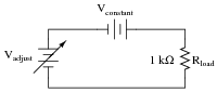
In the following circuit, an adjustable voltage source is connected in series with a resistive load and another voltage source:
|
|
Determine what will happen to the current in this circuit if the adjustable voltage source is increased.
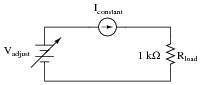
In this next circuit, an adjustable voltage source is connected in series with a resistive load and a current source:
|
|
Now determine what will happen to the current in this second circuit if the adjustable voltage source is increased.
One way to define electrical resistance is by comparing the change in applied voltage (DV) to the change in resultant current (DI). This is mathematically expressed by the following ratio:
|
From the perspective of the adjustable voltage source (Vadjust), and as defined by the above equation, which of these two circuits has the greatest resistance? What does this result suggest about the equivalent resistance of a constant-voltage source versus the equivalent resistance of a constant-current source?
Follow-up question: calculate R as defined by the formula [(DV)/(DI)] for these two circuits, assuming Vadjust changes from 15 volts to 16 volts (1 volt DV):
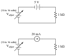
|
|
Notes:
If students are unable to analyze the two circuits qualitatively as suggested in the question, the follow-up question should clear things up. The point of all this, of course, is for students to see that a constant voltage source has zero internal resistance and that a constant current source has infinite internal resistance.
In case anyone should ask, the proper definition for resistance is expressed as a derivative. That is, instead of R = [(DV)/(DI)] we should have R = [dV/dI].
Question 25:
A practical current source may be built using a battery and a special semiconductor component known as a current-limiting diode:
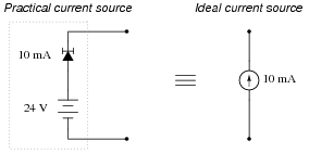
|
|
The current-limiting diode acts as a variable resistance, to regulate current through it at a constant value: if current increases, its resistance increases to reduce the current back to where it should be; if current decreases, its resistance decreases to increase current up to where it should be.
Determine the amount of voltage output by an open-circuited (ideal) current source. Contrast this with the voltage output by the practical current source shown in the diagram. Finally, draw an equivalent circuit showing an ideal current source somehow connected to a resistance in such a way that its open-circuited output voltage is identical to the practical current source.
Equivalent circuit:
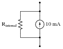
|
|
Follow-up question: the more ïdeal" a current source is, the (choose one: greater, or less) its internal resistance will be. Compare this with the internal resistance of an ideal voltage source.
Notes:
A point of difficulty with some students is the word infinite. I have found it surprisingly common for students to confuse the concept ïnfinite" with the concept ïnfinitesimal". If any of your students are confused in the same manner, it will become evident when they try to explain the open-circuit output voltage of an ideal current source.
Question 26:
Electrochemical batteries are supposed to act as constant voltage sources, outputting an unchanging voltage for a wide range of load currents. The output voltage of real batteries, though, always ßags" to some degree under the influence of a load.
Explain why this is so, in terms of modeling the battery as an ideal voltage source combined with a resistance. How do you suggest the internal resistance of a chemical battery be experimentally measured?
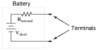
|
|
I'll let you figure out how to measure this internal resistance!
Notes:
Although real chemical batteries do not respond as simply as this equivalent circuit would suggest, the model is accurate enough for many purposes.
Question 27:
Load lines are special types of graphs used in electronics to characterize the output voltage and current behavior of different power sources:
|
|
If we know that all the internal components of a power source are inherently linear, we know that the load line plot will indeed by a straight line. And, if we know the plot will be a straight line, all we need in order to plot a complete load line are two data points.
Usually, the easiest data points to gather for a circuit - whether it be a real circuit or an hypothetical circuit existing on paper only - is the open-circuit condition and the short-circuit condition. In other words, we see how much voltage the source will output with no load connected (Iload = 0 milliamps) and then we see how much current the source will output into a direct short (Vload = 0 volts):
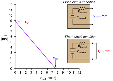
|
|
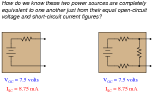
Suppose we have two differently-constructed power sources, yet both of these sources share the same open-circuit voltage (VOC) and the same short-circuit current (ISC). Assuming the internal components of both power sources are linear in nature, explain how we would know without doubt that the two power sources were electrically equivalent to one another. In other words, explain how we would know just from the limited data of VOC and ISC that these two power sources will behave exactly the same when connected to the same load resistance, whatever that load resistance may be.
|
|
Notes:
This is a "poor man's proof" of Thévenin's and Norton's theorems: that we may completely characterize a power source in a simple, equivalent circuit by finding the original circuit's open-circuit voltage and short-circuit current. The assumption of linearity allows us to define the load line for each power source from just these two data points.
Question 28:
Suppose you were handed a black box with two metal terminals on one side, for attaching electrical (wire) connections. Inside this box, you were told, was a voltage source connected in series with a resistance.

|
|
Your task was to experimentally determine the values of the voltage source and the resistor inside the box, and you did just that. From your experimental data you then sketched a circuit with the following component values:
|
|
However, you later discovered that you had been tricked. Instead of containing a single voltage source and a single resistance, the circuit inside the box actually looked like this:
|
|
Demonstrate that these two different circuits are indistinguishable from the perspective of the two metal terminals, and explain what general principle this equivalence represents.
Notes:
Ask your students to clearly state Thévenin's Theorem, and explain how it may be applied to the two-resistor circuit to obtain the one-resistor circuit.
Question 29:
Examine this circuit, consisting of an ideal voltage source and several resistors:
|
|
First, calculate the voltage seen at the load terminals with a voltmeter directly connected across them (an open-circuit condition):
|
|
Next, calculate the current seen at the load terminals with an ammeter directly connected across them (a short-circuit condition):
|
|
Based on these open- and short-circuit calculations, draw a new circuit consisting of a single voltage source and a single (series) resistor that will respond in the exact same manner. In other words, design an equivalent circuit for the circuit shown here, using the minimum number of possible components.
|
|
Follow-up question: is this circuit truly equivalent to the original shown in the question? Sure, it responds the same under extreme conditions (open-circuit and short-circuit), but will it respond the same as the original circuit under modest load conditions (say, with a 5 kW resistor connected across the load terminals)?
Notes:
The purpose of this question is to get students thinking about Thévenin equivalent circuits from the perspective of how the original circuit responds to extreme variations in load resistance.
This question is also a good review of voltmeter and ammeter behavior: that ideal voltmeters act as open circuits (infinite input resistance) while ideal ammeters act as short circuits (zero input impedance).
Question 30:
An electric arc welder is a low-voltage, high-current power source used to generate hot arcs capable of melting metal. Note the voltage and current measurements taken for this particular welder:
|
|
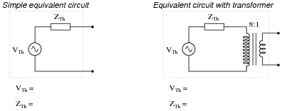
Determine two Thévenin equivalent circuits for the arc welder. The first circuit will simply be an AC voltage source and an internal impedance. The second circuit will be a voltage source and internal impedance connected through an ideal transformer with a step-down ratio of 8 to 1:

|
|
VTh = 45.8 volts
ZTh = 0.2478 W
Equivalent circuit with transformer
VTh = 366.4 volts
ZTh = 15.86 W
Notes:
This practical scenario shows how Thévenin's theorem may be used to "model" a complex device as two simple components (voltage source and resistor). Of course, we must make certain assumptions when modeling in this fashion: we assume, for instance, that the arc welder is a linear device, which may or may not be true.
Question 31:
An electric arc welder is a low-voltage, high-current power source used to generate hot arcs capable of melting metal. Note the voltage and current measurements taken for this particular welder:

|
|
Determine two Thévenin equivalent circuits for the arc welder. The first circuit will simply be an AC voltage source and an internal impedance. The second circuit will be a voltage source and internal impedance connected through an ideal transformer with a step-down ratio of 8 to 1:
|
|
VTh = 48.5 volts
ZTh = 0.230 W
Equivalent circuit with transformer
VTh = 388 volts
ZTh = 14.72 W
Notes:
This practical scenario shows how Thévenin's theorem may be used to "model" a complex device as two simple components (voltage source and resistor). Of course, we must make certain assumptions when modeling in this fashion: we assume, for instance, that the arc welder is a linear device, which may or may not be true.
Question 32:
Is it possible to regard this complex network of power sources and resistances as a simple voltage source (one ideal voltage source in series with an internal resistance), or as a simple current source (one ideal current source in parallel with an internal resistance)? Why or why not?
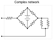
|
|
Follow-up question: why would anyone want to represent this complex network as either a simple voltage source or a simple current source?
Notes:
Ask your students what it means for an electrical or electronic component to be considered "linear," and also what it means to be considered "bilateral." Can they give examples of components that are nonlinear, and/or unilateral?
Question 33:
Give a step-by-step procedure for "Nortonizing" any circuit: finding the Norton equivalent current (VNorton) and Norton equivalent resistance (RNorton).
- �
- Step #1:
- �
- Step #2:
Follow-up question: describe the difference in how one must consider voltage sources versus current sources when calculating the equivalent circuit's resistance (RNorton) of a complex circuit containing both types of sources?
Notes:
I really mean what I say here about looking this up in a textbook. Norton's Theorem is a very well-covered subject in many books, and so it is perfectly reasonable to expect students will do this research on their own and come back to class with a complete answer.
The follow-up question is very important, because some circuits (especially transistor amplifier circuits) contain both types of sources. Knowing how to consider each one in the process of calculating the Norton equivalent resistance for a circuit is very important. When performing this analysis on transistor amplifiers, the circuit often becomes much simpler than its original form with all the voltage sources shorted and current sources opened!
Question 34:
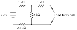
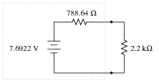
Use Thévenin's Theorem to determine a simple equivalent circuit for the 10 volt source, the 5 kW resistor, and the 2.2 kW resistor; then calculate the voltage across the 1 kW load:
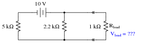
|
|
This exercise may seem pointless, as it is easy enough to obtain the answer simply by series-parallel analysis of this circuit. However, there is definite value in determining a Thévenin equivalent circuit for the voltage source, 5 kW resistor, and 2.2 kW resistor if the load voltage for several different values of load resistance needs to be predicted. Explain why Thévenin's Theorem becomes the more efficient way to predict load voltage if multiple load resistor values are considered.
Notes:
Ask your students to show how (step-by-step) they arrived at the equivalent circuit, prior to calculating load voltage.
In case students are unfamiliar with the "double-chevron" symbols in the schematic diagram, let them know that these represent male/female connector pairs.
Question 35:
Use Thévenin's Theorem to determine a simple equivalent circuit for the 3 mA source, the 8 kW resistor, and the 3.3 kW resistor; then calculate the voltage across the 1 kW load:
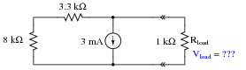
|
|
Follow-up question: although analyzing this circuit by series-parallel analysis is probably easier than using Thévenin's Theorem, there is definite value to doing it the way this question instructs when considering many different load resistance possibilities. Explain why this is.
Notes:
Ask your students to show how (step-by-step) they arrived at the equivalent circuit, prior to calculating load voltage.
In case students are unfamiliar with the "double-chevron" symbols in the schematic diagram, let them know that these represent male/female connector pairs.
Question 36:
Convert the following Thévenin equivalent circuit into a Norton equivalent circuit:
|
|
|
|
Notes:
Nothing special here, just practice converting between Thevenin and Norton sources. Be sure to ask your students to explain all their steps and reasoning in arriving at the answer.
Question 37:
Convert the following Norton equivalent circuit into a Thévenin equivalent circuit:
|
|
|
|
Notes:
Nothing special here, just practice converting between Thevenin and Norton sources. Be sure to ask your students to explain all their steps and reasoning in arriving at the answer.
Question 38:
An ideal (perfect) current source is an abstraction with no accurate realization in life. However, we may approximate the behavior of an ideal current source with a high-voltage source and large series resistance:
|
|
Such a Thevenin equivalent circuit, however imperfect, will maintain a fairly constant current through a wide range of load resistance values.
Similarly, an ideal (perfect) voltage source is an abstraction with no accurate realization in life. Thankfully, though, it is not difficult to build voltage sources that are relatively close to perfect: circuits with very low internal resistance such that the output voltage sags only a little under high-current conditions.
But suppose we lived in a world where things were the opposite: where close-to-ideal current sources were simpler and more plentiful than close-to-ideal voltage sources. Draw a Norton equivalent circuit showing how to approximate an ideal voltage source using an ideal (perfect) current source and a shunt resistance.
|
|
Notes:
This question is not so much a practical one as it is designed to get students to think a little deeper about the differences between ideal voltage and current sources. In other words, it focuses on concepts rather than application.
Question 39:
One day an electronics student decides to build her own variable-voltage power source using a 6-volt battery and a 10 kW potentiometer:
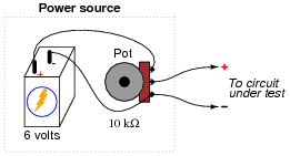
|
|
She tests her circuit by connecting a voltmeter to the output terminals and verifying that the voltage does indeed increase and decrease as the potentiometer knob is turned.
Later that day, her instructor assigns a quick lab exercise: measure the current through a parallel resistor circuit with an applied voltage of 3 volts, as shown in the following schematic diagram.
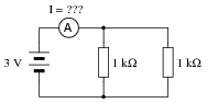
|
|
Calculating current in this circuit is a trivial exercise, she thinks to herself: 3 V � 500 W = 6 mA. This will be a great opportunity to use the new power source circuit, as 3 volts is well within the voltage adjustment range!
She first sets up her circuit to output 3 volts precisely (turning the 10 kW potentiometer to the 50% position), measuring with her voltmeter as she did when initially testing the circuit. Then she connects the output leads to the two parallel resistors through her multimeter (configured as an ammeter), like this:
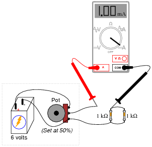
|
|
However, when she reads her ammeter display, the current only measures 1 mA, not 6 mA as she predicted. This is a very large discrepancy between her prediction and the measured value for current!
Use Thévenin's Theorem to explain what went wrong in this experiment. Why didn't her circuit behave as she predicted it would?
Follow-up question #1: explain what this student would have to do to use her adjustable-voltage power source circuit to properly demonstrate the lab circuit as assigned.
Follow-up question #2: identify at least one circuit failure which would result in zero measured (ammeter) current.
Notes:
This challenges students to apply Thévenin's Theorem to a practical scenario: a loaded voltage divider. Be sure to ask your students to show what the Thévenin equivalent circuit for the student's power source is (set at 50%, or 3 volts output unloaded), and how they arrived at that equivalent circuit.
Question 40:
Observe the following circuit:
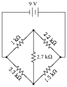
|
|
Note that it is not reducible to a single resistance and power source. In other words, it is not a series-parallel combination circuit. And, while it is a bridge circuit, you are not able to simply analyze the resistor ratios because it is obviously not in a state of balance!
If you were asked to calculate voltage or current for any component in this circuit, it would be a difficult task . . . unless you know either Thévenin's or Norton's theorems, that is! Apply either one of these theorems to the determination of voltage across the 2.2 kW resistor.
Hint: consider the 2.2 kW resistor as the load in a Thévenin or Norton equivalent circuit.
Hint: the Thévenin equivalent circuit looks like this (with the 2.2 kW resistor connected as the load):
|
|
Notes:
Both Thévenin's and Norton's theorems are powerful circuit analysis tools, if you know how to apply them! Students often have difficulty seeing how to analyze the bridge circuit (with the "load" resistor removed), using series-parallel and redrawing techniques. Be prepared to help them through this step during discussion time.
Question 41:
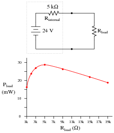
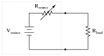
Plot the power dissipation of the load resistance, for several values between 1 kW and 20 kW:
|
|
At what load resistance value is the load's power dissipation maximized?
|
|
Notes:
What practical application can you think of for this principle of power maximization? In what applications might we be interested in delivering the maximum amount of power possible to a load?
Question 42:
Explain what the Maximum Power Transfer Theorem is, in your own words.
Notes:
This theorem is very easy to research, being described in just about every introductory electronics textbook. While it may not be intuitive, at least it is useful and easy to remember!
Question 43:
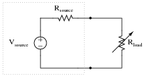
At what load resistance value is the power dissipation maximized for the source's internal resistance?
|
|
Notes:
The wrong answer anticipated in the Änswer" section reflects a common student misconception, and a tendency to memorize simple rules rather than think and analyze circuit behavior. Remind your students that the Maximum Power Transfer Theorem specifies what value the load resistance should be at to maximize power dissipation at that same load, not elsewhere.
Question 44:
Explain why it is important for optimum performance to connect speakers of the proper impedance to an audio power amplifier.
Follow-up question: since consumer-grade audio speakers are typically uniform in impedance (8 W is a very popular value), how would it be possible to connect a wrong speaker impedance to an audio power amplifier?
Notes:
I find it typical that students of electronics new to basic electrical theory are fascinated by discussions related to audio technology, as it is difficult to find someone who does not in some way appreciate music. This is a good thing, for the more "real" you can make your students' classroom experience, the better they will learn.
Question 45:
At what source resistance value is the power dissipation maximized for the load?
|
|
Notes:
The wrong answer anticipated in the Änswer" section reflects a common student misconception, and a tendency to memorize simple rules rather than think and analyze circuit behavior. Remind your students that the Maximum Power Transfer Theorem specifies what value the load resistance should be at to maximize power dissipation at that same load, not elsewhere.
Question 46:
Suppose we were planning to use a photovoltaic panel to generate electricity and electrolyze water into hydrogen and oxygen gas:
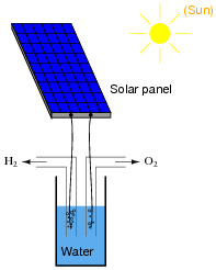
|
|
Our goal is to electrolyze as much water as possible, and this means we must maximize the electrolysis cell's power dissipation. Explain how we could experimentally determine the optimum internal resistance of the electrolysis cell, prior to actually building it, using nothing but the solar panel, a rheostat, and a DMM (digital multimeter).
Follow-up question: assuming that the open-circuit voltage of this solar panel were high enough to pose a shock hazard, describe a procedure you might use to safely connect a "test load" to the panel.
Notes:
Students should at this point understand the maximum power transfer theorem, and also the concept of a voltage source having a certain amount of internal resistance. The "trick" of this question is, of course, how to determine the panel's internal resistance. Do not be surprised if a student suggests using the meter to measure the panel's resistance directly (though this will not work with a real photovoltaic panel).
Regarding the safety-oriented follow-up question, you might want to ask your students what the commonly accepted ßhock hazard" voltage level is (30 volts).