Thyristors
Question 1:
| Don't just sit there! Build something!! |
Learning to mathematically analyze circuits requires much study and practice. Typically, students practice by working through lots of sample problems and checking their answers against those provided by the textbook or the instructor. While this is good, there is a much better way.
You will learn much more by actually building and analyzing real circuits, letting your test equipment provide the änswers" instead of a book or another person. For successful circuit-building exercises, follow these steps:
- 1.
- Carefully measure and record all component values prior to circuit construction, choosing resistor values high enough to make damage to any active components unlikely.
- 2.
- Draw the schematic diagram for the circuit to be analyzed.
- 3.
- Carefully build this circuit on a breadboard or other convenient medium.
- 4.
- Check the accuracy of the circuit's construction, following each wire to each connection point, and verifying these elements one-by-one on the diagram.
- 5.
- Mathematically analyze the circuit, solving for all voltage and current values.
- 6.
- Carefully measure all voltages and currents, to verify the accuracy of your analysis.
- 7.
- If there are any substantial errors (greater than a few percent), carefully check your circuit's construction against the diagram, then carefully re-calculate the values and re-measure.
When students are first learning about semiconductor devices, and are most likely to damage them by making improper connections in their circuits, I recommend they experiment with large, high-wattage components (1N4001 rectifying diodes, TO-220 or TO-3 case power transistors, etc.), and using dry-cell battery power sources rather than a benchtop power supply. This decreases the likelihood of component damage.
As usual, avoid very high and very low resistor values, to avoid measurement errors caused by meter "loading" (on the high end) and to avoid transistor burnout (on the low end). I recommend resistors between 1 kW and 100 kW.
One way you can save time and reduce the possibility of error is to begin with a very simple circuit and incrementally add components to increase its complexity after each analysis, rather than building a whole new circuit for each practice problem. Another time-saving technique is to re-use the same components in a variety of different circuit configurations. This way, you won't have to measure any component's value more than once.
Notes:
It has been my experience that students require much practice with circuit analysis to become proficient. To this end, instructors usually provide their students with lots of practice problems to work through, and provide answers for students to check their work against. While this approach makes students proficient in circuit theory, it fails to fully educate them.
Students don't just need mathematical practice. They also need real, hands-on practice building circuits and using test equipment. So, I suggest the following alternative approach: students should build their own "practice problems" with real components, and try to mathematically predict the various voltage and current values. This way, the mathematical theory "comes alive," and students gain practical proficiency they wouldn't gain merely by solving equations.
Another reason for following this method of practice is to teach students scientific method: the process of testing a hypothesis (in this case, mathematical predictions) by performing a real experiment. Students will also develop real troubleshooting skills as they occasionally make circuit construction errors.
Spend a few moments of time with your class to review some of the "rules" for building circuits before they begin. Discuss these issues with your students in the same Socratic manner you would normally discuss the worksheet questions, rather than simply telling them what they should and should not do. I never cease to be amazed at how poorly students grasp instructions when presented in a typical lecture (instructor monologue) format!
A note to those instructors who may complain about the "wasted" time required to have students build real circuits instead of just mathematically analyzing theoretical circuits:
What is the purpose of students taking your course?
If your students will be working with real circuits, then they should learn on real circuits whenever possible. If your goal is to educate theoretical physicists, then stick with abstract analysis, by all means! But most of us plan for our students to do something in the real world with the education we give them. The "wasted" time spent building real circuits will pay huge dividends when it comes time for them to apply their knowledge to practical problems.
Furthermore, having students build their own practice problems teaches them how to perform primary research, thus empowering them to continue their electrical/electronics education autonomously.
In most sciences, realistic experiments are much more difficult and expensive to set up than electrical circuits. Nuclear physics, biology, geology, and chemistry professors would just love to be able to have their students apply advanced mathematics to real experiments posing no safety hazard and costing less than a textbook. They can't, but you can. Exploit the convenience inherent to your science, and get those students of yours practicing their math on lots of real circuits!
Question 2:
All thyristor devices exhibit the property of hysteresis. From an electrical perspective, what is "hysteresis"? How does this behavior differ from that of "normal" active semiconductor components such as bipolar or field-effect transistors?
Notes:
The hysteretic action of thyristors is often referred to as latching. Ask your students to relate this term to the action of a thyristor. Why is "latching" an appropriate term for this behavior? Can your students think of any applications for such a device?
Question 3:
What is required to make a Shockley diode or DIAC begin conducting current? What condition(s) have to be met in order for electrical conduction to occur through one of these devices?
Also, explain what must be done to stop the flow of electric current through a Shockley diode or a DIAC.
Turn off: current through the device must be brought to a minimum level before the device stops conducting (low-current dropout).
Notes:
Although the answer may seem obvious to many, it is worthwhile to ask your students how the behavior of a Shockley diode compares to that of a normal (rectifying) diode. The fact that the Shockley diode is called a "diode" at all may have fooled some of your students into thinking that it behaves much like a normal diode.
Ask you students to explain how these two devices (Shockley diodes versus rectifying diodes) are similar. In what ways are they different?
Another good discussion question to bring up is the difference between a Shockley diode and a Schottky diode. Although the names are very similar, the two devices are definitely not!
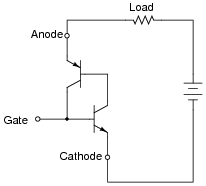
Question 4:
Silicon-controlled rectifiers (SCRs) may be modeled by the following transistor circuit. Explain how this circuit functions, in the presence of and absence of a "triggering" voltage pulse at the gate terminal:
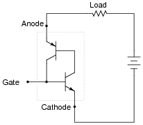
|
|
Notes:
Have students demonstrate the positive feedback "latching" action of this circuit by drawing directions of current on a diagram for the class to see (on the whiteboard, in view of everyone). Ask your students why the circuit "waits" until a triggering pulse to turn on, and why it "latches" on once triggered.
Question 5:
Shown here is an illustration of a large ßtud mount" type of SCR, where the body is threaded so as to be fastened to a metal base like a bolt threads into a nut:
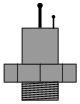
|
|
With no test instrument other than a simple continuity tester (battery and light bulb connected in series, with two test leads), how could you determine the identities of the three terminals on this SCR?
Hint: The threaded metal base of the SCR constitutes one of the three terminals.
Notes:
Ask your students how they know the gate terminal is the smallest one. Why would it be the smallest? Does it have to be the smallest terminal? Why? Also, ask them what continuity indication would distinguish cathode from anode in the continuity test described in the answer.
Question 6:
Explain what happens in each of these circuits when the pushbutton switch is actuated and then released:
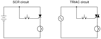
|
|
Follow-up question: explain why these circuits do not behave identically. Aren't SCRs and TRIACs both thyristor (hysteretic) devices? Why doesn't the TRIAC remain in the ön" state after its triggering voltage is removed?
Notes:
This question addresses a very common misunderstanding that students have about TRIACs in AC circuits. Students often mistakenly think that TRIACs will latch AC power just like an SCR latches DC power, simply because the TRIAC is also a hysteretic device. However, this is not true!
One might be inclined to wonder, of what benefit is the TRIAC's hysteresis in an AC circuit, then? If latching is impossible in an AC circuit, then why have TRIACs at all? This is a very good question, and its answer lies in the operation of a TRIAC within the timespan of an AC power cycle, which is much faster than human eyes can see.
Question 7:
Explain what must be done to the SCR to make it turn on and send power to the light bulb:
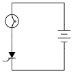
|
|
Next, explain what must be done to turn the SCR off so that the light bulb de-energizes.
Notes:
Let students explain (or perhaps even demonstrate) their answers. It is extremely important for students to realize that SCR's are thyristors, "latching" on and off with transient stimuli. They differ significantly from transistors in this regard.
Question 8:
When an SCR latches ön," it drops very little voltage between anode and cathode. Explain why this is, and what advantage this gives SCRs over transistors when conducting heavy load currents.
Follow-up question: how does the internal operation of an SCR explain its very fast turn-on time, in addition to explaining its low conducting voltage drop?
Notes:
The key to fully answering why an SCR drives itself so hard during conduction is found in the principle of positive feedback. Discuss this principle with your students if they have not already studied it. If they have already studied it, use this question as an opportunity for review.
Question 9:
Explain what a TRIAC is, and how it is at once similar and different from an SCR. What applications might a TRIAC be used in that an SCR would be inappropriate for?
Follow-up question: draw the equivalent circuit for a TRIAC.
Notes:
A popular application for TRIACs is lamp dimmer controls, for line-powered (50 or 60 Hz) incandescent lamps. If time permits, discuss with your students how these lamp dimmer circuits control power to the lamp in a manner reminiscent of PWM (Pulse-Width Modulation).
Question 10:
Label the terminals on a TRIAC with their proper designations:

|
|

|
|
Notes:
Ask your students where they found this information. Was it from a textbook, a datasheet, or some other source?
Question 11:
Explain how Silicon-Controlled Rectifiers (SCRs) differ from TRIACs, in terms of their respective behavior.
Notes:
The answer I give is very minimal by design. Students need to know what "bilateral" means with reference to electronic components, but this question provides a good opportunity for them to learn in case they don't!
Question 12:
Some SCRs and TRIACs are advertised as sensitive-gate devices. What does this mean? What is the difference between a ßensitive gate" SCR and an SCR with a "non-sensitive gate"?
Follow-up question: where would this loading resistor be connected, in the following equivalent diagram for an SCR?
|
|
Notes:
Ask your students why a thyristor such as an SCR or a TRIAC would need to be "de-sensitized" by the addition of a loading resistor? What is wrong with having a ßensitive" thyristor in a circuit?
Question 13:
Explain what a crowbar circuit is, and how it employs an SCR to protect a circuit from excessive voltage.
Notes:
Discuss with your students whether or not they think a crowbar circuit is the sort of mechanism that sees regular use, or whether it is seldom activated.
Question 14:
What is a quadrac, and how does it differ from a regular TRIAC?
Notes:
Ask your students what benefit a quadrac would be over a regular TRIAC.
Question 15:
A student of electronics has just recently learned how to build audio amplifier circuits, and this inspires dreams of designing a super-powerful amplifier for a home entertainment system. One day, this student comes across a donation of electronic components from a local business, and in this donation are several industrial SCRs, rated at 20 amps each.
"Wow," says the student, "these components look like really big transistors, but they're rated for a lot of current. I could build a huge amplifier with these!"
The student approaches you for advice, because you've just recently learned how SCRs function in your electronics class. What do you tell the student, concerning the use of SCRs as audio amplification devices? How do you explain to this excited student that these devices will not work in an amplifier circuit?
Notes:
Believe it or not, I was once approached by an enthusiastic student with this very question!
Question 16:
One way that SCRs may be triggered into their ön" state is by a transient voltage applied between the anode and cathode terminals. Normally, this method of triggering is considered a flaw of the device, as it opens the possibility of unwanted triggering resulting from disturbances in the power supply voltage.
Explain why a high [dv/dt] present on the power supply rail is able to trigger an SCR, with reference to the SCR's equivalent circuit. Also suggest what means might be employed to prevent false triggering from power supply transients.
|
|
Notes:
The expression [dv/dt] is, of course, a calculus term meaning rate-of-change of voltage over time. An important review concept for this question is the Öhm's Law" formula for a capacitance:
|
Only by understanding the effects of a rapidly changing voltage on a capacitance are students able to comprehend why large rates of [dv/dt] could cause trouble for an SCR.
Question 17:
Identify three different ways that an SCR or a TRIAC may be triggered into its ön" (conducting) state:
- 1.
- 2.
- 3.
- 1.
- Applying a voltage pulse at the gate terminal
- 2.
- Exceeding the anode-to-cathode "breakover" voltage
- 3.
- Exceeding the "critical rate of rise" for anode-cathode voltage ([dv/dt])
Notes:
Although gate triggering is by far the most common method of initiating conduction through SCRs and TRIACs, it is important that students realize it is not the only way. The other two methods, both involving voltage applied between the anode and cathode terminals (or MT1-MT2 terminals) of the device, are often accidental means of triggering.
Be sure to discuss with your students the reason why excessive [dv/dt] can trigger a thyristor, based on an examination of inter-electrode capacitance within the transistors of a thyristor model.
Question 18:
Identify two different ways that an SCR or a TRIAC may be forced into its öff" (non-conducting) state:
- 1.
- 2.
- 1.
- Low current dropout (interrupting current with some other switching device)
- 2.
- "Reverse-firing" the gate with a voltage pulse of the "wrong" polarity
Notes:
Although low-current dropout is the most common method of terminating conduction through SCRs and TRIACs, it is important that students realize it is not the only way. The other method, though, is often very difficult to achieve with ordinary SCRs or TRIACs.
Question 19:
The unijunction transistor, or UJT, is an interesting device, exhibiting hysteresis just like SCRs and TRIACs. Its schematic symbol is as follows:
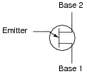
|
|
One equivalent circuit diagram for the UJT uses a pair of transistors and a pair of resistors:
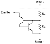
|
|
When the two base terminals of a UJT are connected across a source of DC voltage, the two base resistances (RB1 and RB2) form a voltage divider, splitting the applied voltage into lesser portions:
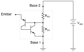
|
|
How much voltage, and of what polarity, must be applied to the emitter terminal of the UJT to turn it on? Write an equation solving for the magnitude of this triggering voltage (symbolized as VP), given RB1, RB2, and VBB.
|
Follow-up question: how is the the standoff ratio defined for a UJT, and how might this equation be re-written to include it?
Notes:
The standoff ratio is perhaps the most important UJT parameter, given the hysteretic switching function of this device. Writing the equation for trigger voltage (VP) and understanding the definition for standoff ratio requires that students remember the voltage divider formula from their studies in DC circuits:
|
This question provides a good opportunity to review the operation of voltage divider circuits, and this formula in particular.
Question 20:
A unijunction transistor with an intrinsic standoff ratio (h) of 0.8 is powered by a 15 volt DC source. Calculate the emitter voltage needed to "trigger" this UJT into its conductive state.
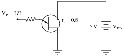
|
|
Notes:
Nothing special here, just practice calculating the trigger voltage. Note to your students that the symbol for the intrinsic standoff ratio (h) is the Greek letter ëta," which also happens to be used to symbolize efficiency.
Question 21:
Describe what happens to the UJT as the potentiometer is slowly adjusted upward to provide a variable voltage at point A in this circuit, starting from 0 volts and ending at the trigger voltage VP:
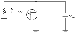
|
|
Now describe what must be done to the potentiometer to cause the UJT to turn back off again.
Notes:
Ask your students to describe how hysteresis is exhibited by the UJT in this scenario.
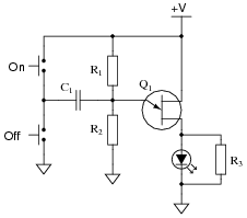
Question 22:
This circuit uses a unijunction transistor (UJT) to latch an LED in the ön" state with a positive pulse at the input terminal. A negative voltage pulse at the input terminal turns the LED off:
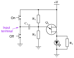
|
|
Explain how the unijunction transistor functions in this circuit.
Challenge question: what is the purpose of resistor R3 in this circuit?
Notes:
Ask your students to identify the terminals on the UJT. The designations for each terminal may be surprising to your students, given the names of bipolar transistor terminals!
The challenge question may only be answered if one carefully considers the characteristics of an LED. Resistor R3 helps overcome problems that might potentially arise due to the nonlinearities of the diode in its off state.
I got this circuit from the October 2003 issue of Electronics World magazine, in their regular "Circuit Ideas" section. The design is attributed to André de Guérin.
Question 23:
Predict how the operation of this UJT latch circuit will be affected as a result of the following faults. Consider each fault independently (i.e. one at a time, no multiple faults):
|
|
- �
- Capacitor C1 fails open:
- �
- Capacitor C1 fails shorted:
- �
- Resistor R1 fails open:
- �
- Solder bridge (short) past resistor R1:
- �
- Resistor R2 fails open:
- �
- Solder bridge (short) past resistor R2:
For each of these conditions, explain why the resulting effects will occur.
- �
- Capacitor C1 fails open: Neither pushbutton switch has any effect on the LED.
- �
- Capacitor C1 fails shorted: Circuit behaves normally.
- �
- Resistor R1 fails open: LED always off, refuses to turn on.
- �
- Solder bridge (short) past resistor R1: LED always on, refuses to turn off.
- �
- Resistor R2 fails open: LED always on, refuses to turn off.
- �
- Solder bridge (short) past resistor R2: LED always off, refuses to turn on.
Notes:
The purpose of this question is to approach the domain of circuit troubleshooting from a perspective of knowing what the fault is, rather than only knowing what the symptoms are. Although this is not necessarily a realistic perspective, it helps students build the foundational knowledge necessary to diagnose a faulted circuit from empirical data. Questions such as this should be followed (eventually) by other questions asking students to identify likely faults based on measurements.
Question 24:
Identify at least three different types of thyristors (besides SCRs):
- 1.
- 2.
- 3.
- 1.
- DIAC
- 2.
- TRIAC
- 3.
- Quadrac (TRIAC + DIAC)
- 4.
- Shockley diode
- 5.
- GTO
- 6.
- UJT
- 7.
- SCS
Notes:
Challenge your students to identify even more types of thyristors, if they can!
Question 25:
Find one or two silicon-controlled rectifiers and bring them with you to class for discussion. Identify as much information as you can about your SCRs prior to discussion:
- �
- Terminal identification (which terminal is gate, anode, and cathode)
- �
- Continuous voltage rating
- �
- Continuous current rating
- �
- Continuous power rating
- �
- Whether or not it is a ßensitive gate" device
Be prepared to prove the terminal identifications of your SCRs in class, by using a multimeter!
Notes:
The purpose of this question is to get students to kinesthetically interact with the subject matter. It may seem silly to have students engage in a ßhow and tell" exercise, but I have found that activities such as this greatly help some students. For those learners who are kinesthetic in nature, it is a great help to actually touch real components while they're learning about their function. Of course, this question also provides an excellent opportunity for them to practice interpreting component markings, use a multimeter, access datasheets, etc.