Thyristor application circuits
Question 1:
| Don't just sit there! Build something!! |
Learning to mathematically analyze circuits requires much study and practice. Typically, students practice by working through lots of sample problems and checking their answers against those provided by the textbook or the instructor. While this is good, there is a much better way.
You will learn much more by actually building and analyzing real circuits, letting your test equipment provide the änswers" instead of a book or another person. For successful circuit-building exercises, follow these steps:
- 1.
- Carefully measure and record all component values prior to circuit construction, choosing resistor values high enough to make damage to any active components unlikely.
- 2.
- Draw the schematic diagram for the circuit to be analyzed.
- 3.
- Carefully build this circuit on a breadboard or other convenient medium.
- 4.
- Check the accuracy of the circuit's construction, following each wire to each connection point, and verifying these elements one-by-one on the diagram.
- 5.
- Mathematically analyze the circuit, solving for all voltage and current values.
- 6.
- Carefully measure all voltages and currents, to verify the accuracy of your analysis.
- 7.
- If there are any substantial errors (greater than a few percent), carefully check your circuit's construction against the diagram, then carefully re-calculate the values and re-measure.
When students are first learning about semiconductor devices, and are most likely to damage them by making improper connections in their circuits, I recommend they experiment with large, high-wattage components (1N4001 rectifying diodes, TO-220 or TO-3 case power transistors, etc.), and using dry-cell battery power sources rather than a benchtop power supply. This decreases the likelihood of component damage.
As usual, avoid very high and very low resistor values, to avoid measurement errors caused by meter "loading" (on the high end) and to avoid transistor burnout (on the low end). I recommend resistors between 1 kW and 100 kW.
One way you can save time and reduce the possibility of error is to begin with a very simple circuit and incrementally add components to increase its complexity after each analysis, rather than building a whole new circuit for each practice problem. Another time-saving technique is to re-use the same components in a variety of different circuit configurations. This way, you won't have to measure any component's value more than once.
Notes:
It has been my experience that students require much practice with circuit analysis to become proficient. To this end, instructors usually provide their students with lots of practice problems to work through, and provide answers for students to check their work against. While this approach makes students proficient in circuit theory, it fails to fully educate them.
Students don't just need mathematical practice. They also need real, hands-on practice building circuits and using test equipment. So, I suggest the following alternative approach: students should build their own "practice problems" with real components, and try to mathematically predict the various voltage and current values. This way, the mathematical theory "comes alive," and students gain practical proficiency they wouldn't gain merely by solving equations.
Another reason for following this method of practice is to teach students scientific method: the process of testing a hypothesis (in this case, mathematical predictions) by performing a real experiment. Students will also develop real troubleshooting skills as they occasionally make circuit construction errors.
Spend a few moments of time with your class to review some of the "rules" for building circuits before they begin. Discuss these issues with your students in the same Socratic manner you would normally discuss the worksheet questions, rather than simply telling them what they should and should not do. I never cease to be amazed at how poorly students grasp instructions when presented in a typical lecture (instructor monologue) format!
A note to those instructors who may complain about the "wasted" time required to have students build real circuits instead of just mathematically analyzing theoretical circuits:
What is the purpose of students taking your course?
If your students will be working with real circuits, then they should learn on real circuits whenever possible. If your goal is to educate theoretical physicists, then stick with abstract analysis, by all means! But most of us plan for our students to do something in the real world with the education we give them. The "wasted" time spent building real circuits will pay huge dividends when it comes time for them to apply their knowledge to practical problems.
Furthermore, having students build their own practice problems teaches them how to perform primary research, thus empowering them to continue their electrical/electronics education autonomously.
In most sciences, realistic experiments are much more difficult and expensive to set up than electrical circuits. Nuclear physics, biology, geology, and chemistry professors would just love to be able to have their students apply advanced mathematics to real experiments posing no safety hazard and costing less than a textbook. They can't, but you can. Exploit the convenience inherent to your science, and get those students of yours practicing their math on lots of real circuits!
Question 2:
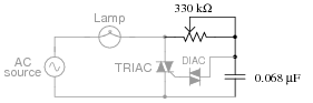
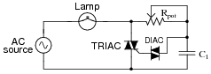
In this circuit, a series resistor-capacitor network creates a phase-shifted voltage for the "gate" terminal of a power-control device known as a TRIAC. All portions of the circuit except for the RC network are ßhaded" for de-emphasis:
|
|
Calculate how many degrees of phase shift the capacitor's voltage is, compared to the total voltage across the series RC network, assuming a frequency of 60 Hz, and a 50% potentiometer setting.
Challenge question: what effect will a change in potentiometer setting have on this phase angle? Specifically, will increasing the resistance make the phase shift approach -90o or approach 0o?
Notes:
In this question, I purposely omitted any reference to voltage levels, so the students would have to set up part of the problem themselves. The goal here is to build problem-solving skills.
Question 3:
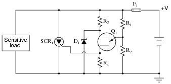
The following schematic diagram shows a simple crowbar circuit used to protect a sensitive DC load from accidental overvoltages in the supply power (+V):
|
|
Here, the UJT serves as an overvoltage detection device, triggering the SCR when necessary. Explain how this circuit works, and what the function of each of its components is.
- �
- F1 protects the voltage source from damage
- �
- R1 and R2 provide a divided sample of +V
- �
- R3 and D1 provide a reference ("threshold") voltage
- �
- Q1 detects the overvoltage condition
- �
- R4 de-sensitizes the SCR gate
- �
- SCR1 clamps the output voltage
Notes:
In this question, students must piece together their knowledge of both UJTs and SCRs to analyze the function of the circuit. Perhaps the most complex aspect of it is the divided voltage sensing, whereby the UJT senses only a fraction of the supply voltage in determining whether to trigger or not.
Question 4:
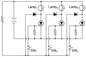
The circuit shown here indicates which pushbutton switch has been actuated first. After actuating any one of the three pushbutton switches (and energizing its respective lamp), none of the other lamps can be made to energize:
|
|
Explain how this circuit works. Why can't any of the other lamps turn on once any one of them has been energized? Also, explain how the circuit could be modified so as to provide a "reset" to turn all lamps off again.
Challenge question: how could this circuit be modified to serve as a "first place" detector for runners competing on three different tracks? Draw a schematic diagram showing suitable sensors (instead of pushbutton switches) for detecting the passage of the three runners.
Notes:
Discuss the operation of this circuit with your students in detail. It serves as an excellent practical example of SCR action, as well as a good review of general diode action. Ask them why an NC switch connected in series with the battery would serve to reset the SCRs.
A good question to challenge students' understanding of this circuit is to ask them how to ëxpand" it to include four, five, or six lamps instead of just three.
I found this circuit design in the October 2003 edition of Electronics World magazine. The original circuit, submitted to this periodical by M.J. Nicholas, appears on page 35 of the magazine in a slightly different form, with four lamp circuits instead of three, and using regular rectifying diodes instead of Schottky diodes as I have shown.
Question 5:
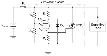
This crowbar circuit has a problem. It used to work just fine, and then one day it blew the fuse. Upon replacing the fuse, the new fuse immediately blew:
|
|
Measuring the supply voltage with a voltmeter, everything checks out well. There does not appear to be an overvoltage condition causing a legitimate "crowbar" event in the circuit. Disconnecting the load from the crowbar circuit and powering it up with a standard bench-top laboratory power supply reveals the load to be in perfect condition. Thus, both the source and the load have been eliminated as possibilities that may have blown the fuse(s).
Moving on to the crowbar circuit itself, identify some component faults that could (each, independently) account for the problem, and explain your reasoning.
- �
- SCR failed shorted
- �
- Zener diode failed shorted
- �
- R1 failed shorted
- �
- R2 failed open
- �
- R4 failed open (especially if SCR is a sensitive-gate type)
- �
- UJT Q1 failed shorted between base terminals
Notes:
Discuss with your students the initial troubleshooting steps described in the question. What strategy or strategies is the technician taking to isolate the problem?
Question 6:
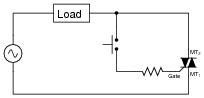
What purpose does the TRIAC serve in this circuit?
|
|
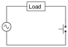
Why use a TRIAC at all? Why not just use the switch to directly handle load current as in this next circuit?
|
|
Notes:
A benefit of this circuit that is easy to miss is the TRIAC's ability to provide zero crossing turn-off. Discuss why this might be important when controlling power to inductive loads.
Question 7:
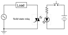
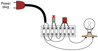
Optically-isolated TRIACs are available for use as solid-state relays, suitable for replacing electromechanical relays in many AC power switching applications:
|
|
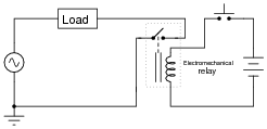
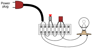
Describe some of the advantages of using a solid-state relay for switching AC power instead of using an electromechanical relay as shown here:
|
|
Also describe any disadvantages to using a solid-state relay, if they exist.
- Advantages
- �
- Less DC drive current required
- �
- No moving parts to wear
- �
- Zero-crossing turn-off naturally provided by the TRIAC
- �
- Any others you can think of . . . ?
- Disadvantages
- �
- Öff" state not as high-impedance as an electromechanical relay
- �
- Susceptible to [dv/dt]-induced turn-on
- �
- Any others you can think of . . . ?
Follow-up question: what is zero-crossing turn-off, and what type of load might benefit most from this feature?
Notes:
It should be noted that the label ßolid-state relay" is not exclusively reserved for opto-TRIAC devices. Many different types of solid-state relays exist, including opto-BJT, opto-FET, and opto-SCR. Be sure to mention this to your students.
Question 8:
Predict how the operation of this AC power control circuit will be affected as a result of the following faults. Consider each fault independently (i.e. one at a time, no multiple faults):
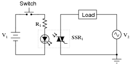
|
|
- �
- Switch contacts fail open:
- �
- Switch contacts fail shorted:
- �
- Resistor R1 fails open:
- �
- Solder bridge (short) past resistor R1:
- �
- Battery (V1) dies:
For each of these conditions, explain why the resulting effects will occur.
- �
- Switch contacts fail open: Load never receives power.
- �
- Switch contacts fail shorted: Load always receives power.
- �
- Resistor R1 fails open: Load never receives power.
- �
- Solder bridge (short) past resistor R1: Load energizes momentarily the first time the switch is actuated, then refuses to turn on after the LED inside the solid-state relay (SSR1) becomes damaged.
- �
- Battery (V1) dies: Load never receives power.
Notes:
The purpose of this question is to approach the domain of circuit troubleshooting from a perspective of knowing what the fault is, rather than only knowing what the symptoms are. Although this is not necessarily a realistic perspective, it helps students build the foundational knowledge necessary to diagnose a faulted circuit from empirical data. Questions such as this should be followed (eventually) by other questions asking students to identify likely faults based on measurements.
Question 9:
This TRIAC circuit has a serious problem. Whenever the pushbutton switch is actuated, the TRIAC explodes!
|
|
Explain why this happens, and what must be done to fix the problem.
Notes:
I've seen students do this a few times, with startling results!
Question 10:
Suppose a student builds the following TRIAC circuit and finds that it does not work:

|
|
When the pushbutton switch is actuated, nothing happens. What is wrong with this circuit? Hint: the problem in this circuit is very subtle, and may be very difficult to discern.
|
|
Notes:
This aspect of TRIACs is often omitted from texts on thyristor devices, but it is important for students to understand. Even though TRIACs are bilateral devices, it still does matter where the triggering voltage is applied (between Gate and MT1, versus Gate and MT2).
Question 11:
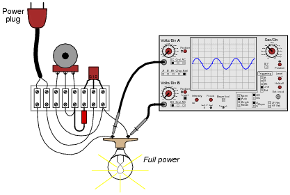
A student builds this simple TRIAC power control circuit to dim a light bulb:
|
|
The only problem with it is the lack of full control over the light bulb's brightness. At one extreme of the potentiometer's range, the light bulb is at full brightness. As the potentiometer is moved toward the direction of dimming, though, the light bulb approaches a medium level of intensity, then suddenly de-energizes completely. In other words, this circuit is incapable of providing fine control of power from öff" to "full" light. The range of control seems to be from full brightness to half-brightness, and nothing below that.
Connecting an oscilloscope across the light bulb terminals (using both channels of the oscilloscope to measure voltage drop in the "differential" mode), the waveform looks like this at full power:
|
|
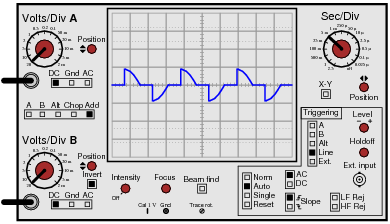
When the potentiometer is adjusted to the position giving minimum light bulb brightness (just before the light bulb completely turns off), the waveform looks like this:
|
|
Explain why this circuit cannot provide continuous adjustment of light bulb brightness below this level.
Follow-up question #1: which direction must the student rotate the potentiometer shaft (CW or CCW) in order to dim the lamp, based on the pictorial diagram shown in the question?
Follow-up question #2: explain how the oscilloscope is being used by the student, with two probes, channel B inverted, and the Ädd" function engaged. Why is this mode of usage important for this kind of voltage measurement?
Notes:
Some students find this concept difficult to grasp, so it may be necessary to discuss what the load power waveforms appear like at different power settings.
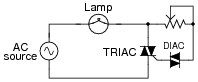
Question 12:
Predict how the operation of this AC lamp dimmer circuit will be affected as a result of the following faults. Consider each fault independently (i.e. one at a time, no multiple faults):
|
|
- �
- Potentiometer Rpot fails open:
- �
- Capacitor C1 fails shorted:
- �
- Capacitor C1 fails open:
- �
- DIAC fails open:
- �
- TRIAC fails shorted:
For each of these conditions, explain why the resulting effects will occur.
- �
- Potentiometer Rpot fails open: Lamp remains off.
- �
- Capacitor C1 fails shorted: Lamp remains off.
- �
- Capacitor C1 fails open: Range of lamp brightness control extends from 100% to 50%, and any attempt to make it dimmer results in the lamp just turning all the way off.
- �
- DIAC fails open: Lamp remains off.
- �
- TRIAC fails shorted: Lamp remains on at 100% brightness.
Notes:
The purpose of this question is to approach the domain of circuit troubleshooting from a perspective of knowing what the fault is, rather than only knowing what the symptoms are. Although this is not necessarily a realistic perspective, it helps students build the foundational knowledge necessary to diagnose a faulted circuit from empirical data. Questions such as this should be followed (eventually) by other questions asking students to identify likely faults based on measurements.
Question 13:
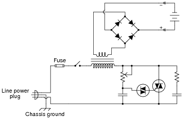
Explain how this battery charger circuit uses a TRIAC to control DC power to the battery:
|
|
Also, identify some component failures in this circuit that could prevent DC power from getting to the battery.
Notes:
The interesting point of this circuit is that by controlling AC power with the TRIAC, DC power to the battery is subsequently controlled.
Ask your students to explain the purpose of each component in the circuit, and pose some troubleshooting questions for them to analyze. There are many possibilities for component failures stopping DC power from getting to the battery. Discuss the examples your students think of, and determine the relatively likelihood of each.
Question 14:
Commutation is an important issue in any kind of thyristor circuit, due to the "latching" nature of these devices. Explain what "commutation" means, and how it may be achieved for various thyristors.
Follow-up question: in some circuits, commutation occurs naturally. In other circuits, special provisions must be made to force the thyristor(s) to turn off. Identify at least one example of a thyristor circuit with natural commutation and at least one example of a thyristor circuit using forced commutation.
Notes:
An important feature of all thyristors is that they latch in the ön" state once having been triggered. This point needs to be emphasized multiple times for some students to grasp it, as they are accustomed to thinking in terms of transistors which do not latch.
Question 15:
The following circuit exhibits very interesting behavior:
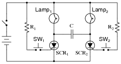
|
|
When the power is first turned on, neither lamp will energize. If either pushbutton switch is then momentarily actuated, the lamp controlled by that SCR will energize. If, after one of the lamps has been energized, the other pushbutton switch is then actuated, its lamp will energize and the other lamp will de-energize.
Stated simply, each pushbutton switch not only serves to energize its respective lamp, but it also serves to de-energize the other lamp as well. Explain how this is possible. It should be no mystery to you why each switch turns on its respective lamp, but how is the other switch able to exert control over the other SCR, to turn it off?
Hint: the secret is in the capacitor, connected between the two SCRs' anode terminals.
Notes:
This method of switching load current between two thyristors is a common technique in power control circuits using SCRs as the switching devices. If students are confused about this circuit's operation, it will help them greatly to analyze the capacitor's voltage drop when SCR1 is conducting, versus when SCR2 is conducting.
Question 16:
The following schematic diagram shows a timer circuit made from a UJT and an SCR:
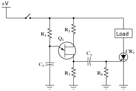
|
|
Together, the combination of R1, C1, R2, R3, and Q1 form a relaxation oscillator, which outputs a square wave signal. Explain how a square wave oscillation is able to perform a simple time-delay for the load, where the load energizes a certain time after the toggle switch is closed. Also explain the purpose of the RC network formed by C2 and R4.
Follow-up question: how would you suggest we modify this circuit to make the time delay adjustable?
Notes:
Knowing that the UJT forms an oscillator, it is tempting to think that the load will turn on and off repeatedly. The first sentence in the answer explains why this will not happen, though.
I got the basic idea for this circuit from the second edition of Electronics for Industrial Electricians, by Stephen L. Herman.